![]()
Installation, Operation, and Maintenance Manual
VCIOM-15590-EN Rev. 0
November 2021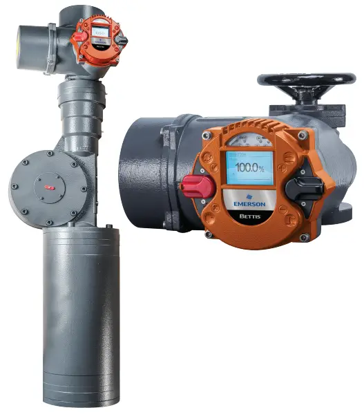
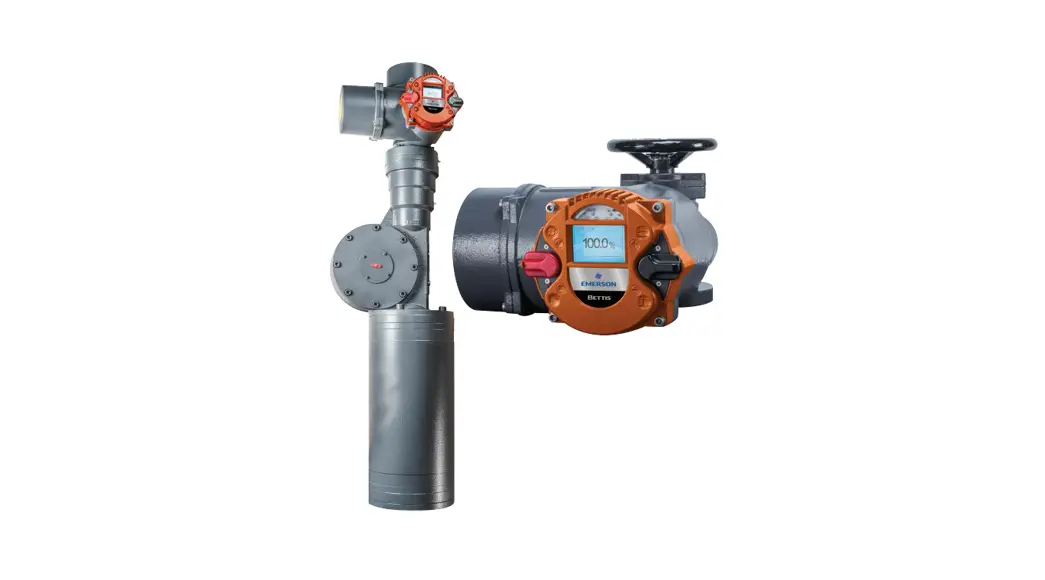
Bettis RTS – PROFIBUS
Additional Board for Bettis RTS Actuators
Section 1: General Information
The Standardized PROFIBUS DP system is available for all Bettis RTS Series of actuators.
This interface is a hardware option and should already be known when ordering the actuator.
Retrofitting is possible but should only be performed by a skilled Emerson technician or by specially trained personnel.
PROFIBUS-DP defines the technical and functional characteristics of a serial Fieldbus system, with which a set of distributed, digital automation devices can be networked with one another. PROFIBUS-DP distinguishes between master and slave devices and is designed to exchange data at the field level.
This is where central control devices, such as PLCs and PCs, communicate with distributed field devices via a fast serial connection.
Data exchange with these decentralized devices is carried out cyclically. The communication functions necessary to do this are defined by the PROFIBUS-DP basic functions according to EN 50170.
Master devices control the data traffic on the bus. A master can send messages without an external request. In the PROFIBUS protocol, masters are also called active participants.
Slave devices such as BETTIS RTS actuators are peripheral devices. Typical slave devices are input/output devices, valves, actuators, and transmitters. They are not given active bus access authorization, i.e. they are only allowed to acknowledge received messages, or, at the request of a master, transmit messages to it. Slaves are also called passive participants.
The master cyclically reads the input information from the slaves and cyclically writes the output information to the slaves. In addition to this cyclic data transmission of the process image, PROFIBUS-DP also offers powerful functions for diagnostics and commissioning purposes. Monitoring functions on the master and slave sides monitor the data traffic.
The transmission technology is based on an RS-485 connection via a shielded twisted-pair cable. Bettis RTS series support baud rates up to 1.5 Mbit/s.
Only cables in accordance with standard DIN 19245 and/or EN 50170-2, cable type A, may be used for PROFIBUS-DP cabling.
Depending on the transmission speed, the following segment lengths are permitted:
Table 1.
| Transmission Speed | Segment Length |
| 9.6 / 19.2 / 93.75 kBd | 1,200 m |
| 187.5 kBd | 1000 m |
| 500 kBd | 400 m |
| 1.5 MBd | 200 m |
A maximum of 32 PROFIBUS devices can be connected in one segment. If more devices are to be connected to a PROFIBUS line, then multiple segments have to be connected by repeaters.
The bus cable has to be installed at a distance of at least 20 cm from other cables and should be installed in a separate, conductive, and earthed cable tray.
It is important to ensure that there are no potential differences between the individual devices on the PROFIBUS.
Section 2: Connection
- Depending on the order, there are the following connection options:
- Standard design: via terminal board
- Explosion-proof design: via terminals
2.1Standard Design
PROFIBUS cables connect via the input/output board in the terminal compartment for the customer’s plug connector for the actuator. The PROFIBUS connection is thus, like the other electrical connections, plug-connectable both for power and signals. When the connecting plug is unplugged, the connection within the line for the PROFIBUS is maintained, i.e., the connecting plug can be unplugged during operation without interrupting the communication to other bus subscribers.
NOTE The PROFIBUS has to be terminated at the end of the line. This active bus termination can be made on the input/output board. The supply for the terminating resistors, however, is carried out from the actuator, i.e., with the plug connector unplugged, the bus termination is not supplied. To avoid such problems, we recommend terminating the bus separately with an active bus termination.
If the PROFIBUS is a single-channel design, the PROFIBUS cables connect on Channel I, and with a dual-channel design (option: redundant), Channel I and Channel II are used.
2.1.1 Terminal Board (Provided by customer)
The terminal board is located in the terminal compartment for the customer’s plug connector beneath the top cover.
Figure 1 Terminal Board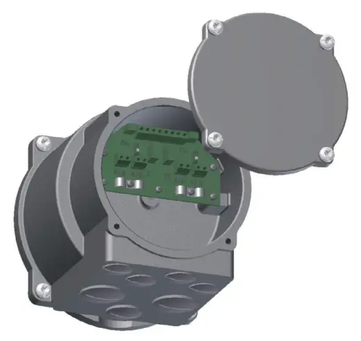
2.1.2 Connecting the PROFIBUS Cables
Recommended cable assembly
Before connecting the bus cable, it has to be assembled as follows: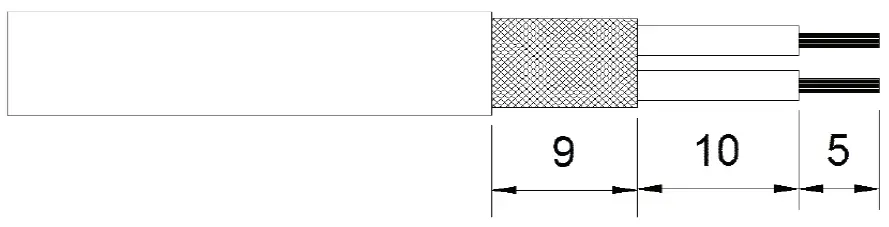 The terminals on the terminal board are designed for a max. cross-section of up to 1.5 mm2. The shield’s outside diameter has to be in the range of 5 – 8 mm.
Customer connection within the line
There is other PROFIBUS subscribers before and after the slave. Connection for the cables:
Figure 2 Single Channel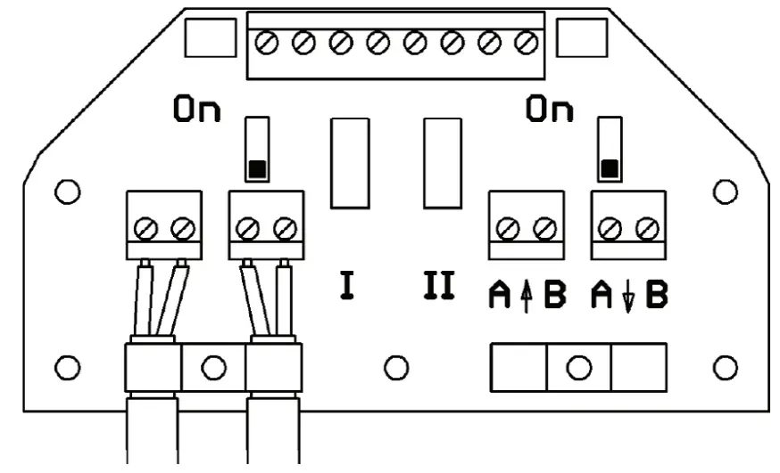 Figure 3 Dual Channel
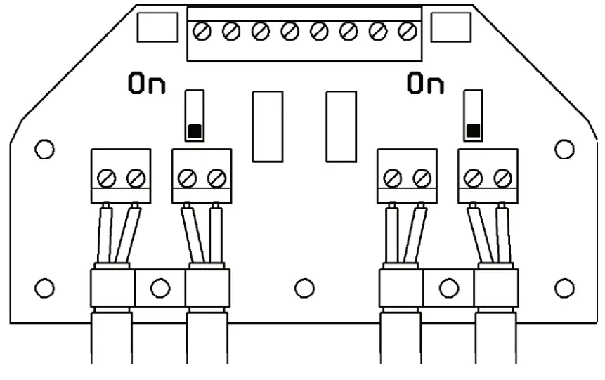
Customer connection at the end of the line, bus termination
There are no further PROFIBUS subscribers before or after the slave. Connection for the cables:
Figure 4 Single Channel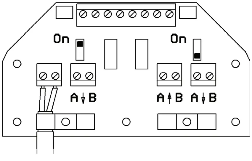 Figure 5 Dual Channel
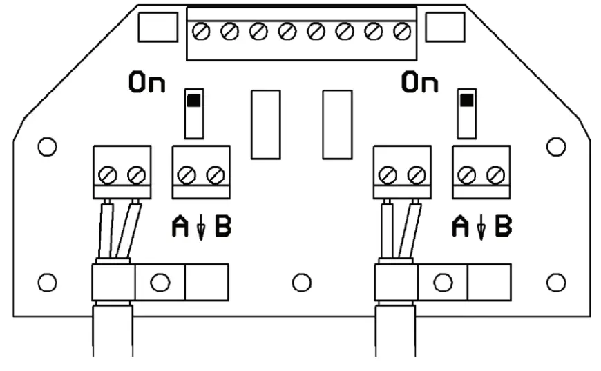 Bus termination:
The bus has to be terminated on both ends of the PROFIBUS line. This termination can be made via the built-in terminating resistors, which are actively supplied by the actuator. The terminating resistors are enabled when the switch on the terminal board is switched to “ON”.
2.2 Explosion-proof Design
Generally, no bus termination is provided in the BETTIS RTS in the explosion-proof design, i.e., the bus has to be implemented on both ends on the system side.
As an option, however, the bus connection can also be implemented in BETTIS RTS. This has to be specified when ordering.
In such case, the bus connection can be enabled by bridging the terminals:
- A to AT
- B to BT (single channel version)
- A1 to A1T
- B1 to B1T
- A2 to A2T
- B2 to B2T (dual channel version).
! WARNING
The shield has to be put on the clamping brackets (cross-section). See Figure 6 or Figure 7.
2.2.1 Design with Additional Binary I/Os
Figure 6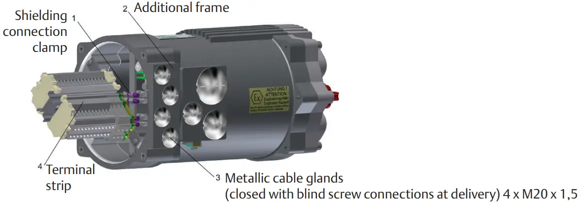
2.2.2 Terminal strip
Figure 7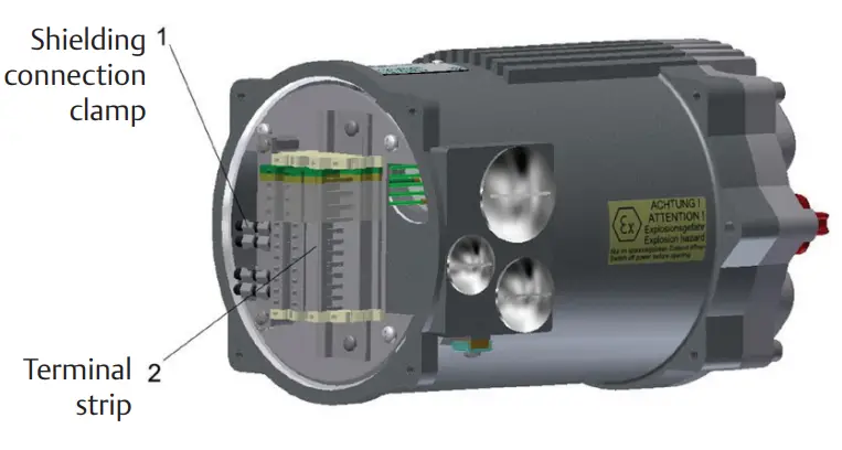
As an option, 4 x M20 drilled holes can be provided for additional cable entries.
Section 3: Commissioning
When commissioning a PROFIBUS-DP network, the devices on the PROFIBUS-DP have to be parameterized and configured with the project configuration software of the control system used (PROFIBUS configurator).
In this step, each subscriber connected to the PROFIBUS also has to be given a unique address.
The project configuration software first reads in the GSD file (General Station Description) of the various actuators. The GSD file contains information about the device’s properties needed by the master. The current GSD file can be downloaded at Emerson Global Sales Portal.
After that, the user can configure and parameterize each device on the PROFIBUS-DP.
This information is stored in the control system (DP master) and sent to the actuators (DP slaves) each time communication starts up.
The following additional parameters become visible in the control unit for the Bettis RTS actuator with the PROFIBUS option enabled.
Table 2.
| Menu Item | Subitem | Options | Explanation/Comments | |
|
P15.1 |
PROFIBUS |
PROFIBUS | 0: disabled | PROFIBUS disabled |
| 1: allow parameter. | Parameterization by the master is allowed. | |||
| (2): ignore paramet. | Parameterization by the master is ignored. Only parameters set in the actuator control system are effective (recommended setting). | |||
| 3: deny paramet. | Parameterisation by the master is not allowed. | |||
| P15.2 | PROFIBUS | Address Channel A | 0 bis 125 | Setting of the bus address for the first, primary channel. |
| P15.3 | PROFIBUS | Address Channel B | 0 bis 125 | Setting the bus address of the second, secondary channel (only with the option “PROFIBUS redundant”). |
| P15.4 | PROFIBUS | Watchdog time | 0.0 – 10.0 s (0.0 s) | Monitoring of the toggle bit transmitted from the master (bit 7 in the command). With a bus watchdog time set, this bit has to toggle within that time; otherwise thereis a bus watchdog error. At 0.0 s the watchdog function is disabled, in which case toggling of the toggle bit may be omitted. |
| P15.5 | PROFIBUS | Setpoint Source | (0): Standard | The set point is specified via PROFIBUS (only relevant when the positioner is enabled) |
| 1: Analog | The set point is specified by the analogue signal (only relevant when the positioner is enabled). | |||
| 2: Bus/Analog | With a fault-free bus, the set point is specified via the PROFIBUS. With a bus error, the analogue value is switched to (only relevant when the positioner is enabled). | |||
| P15.6 | PROFIBUS | Status 2 | (0) | Standard assignment for Status 2. |
| 1 – 2 | Reserved for future use. | |||
| P15.7 | PROFIBUS | Status 3 | (0) | Standard assignment for Status 3 (current event). |
| 1 – 2 | Reserved for future use. | |||
| P15.8 | PROFIBUS | Status 4 | (0) | Standard assignment for Status 4. |
| 1-2 | Reserved for future use. |
NOTE After changing an address, the control unit has to be briefly switched off and back on again in order to apply the change.
Section 4: Description of the Input and Output Data
General information: Depending on the master, it is possible that the low byte (bit 0 – 7) and the high byte (bit 8 – 15) might have to be swapped. The transmission mode (big endian/little endian) always has to be adjusted such that the analogue values are transmitted correctly. Only then can the binary data be swapped.
4.1 Modules for the Input Data
(Data from Master to Slave)
4.1.1 Command
Module number: 23Hex
ID-byte: 60Hex (1 word AA / consistency 1 word)
Data format: 16-bit (bit field)
Structure:
Table 3.
But no. | Function | Description | |
| Bit = 0 | Bit = 1 | ||
| 0 | OPEN | – | OPEN command in REMOTE mode. |
| 1 | CLOSE | – | CLOSE command in REMOTE mode. |
| 2 | STOP | – | STOP command in REMOTE mode. |
| 3 | EMERGENCY – OPEN | – | EMERGENCY – OPEN command in REMOTE & LOCAL modes. |
| 4 | EMERGENCY – CLOSE | – | EMERGENCY – CLOSE command in REMOTE & LOCAL modes. |
| 5 | BLOCK | – | BLOCK actuator in LOCAL & REMOTE modes The actuator is not operable either via the selector switch locally nor via commands by REMOTE nor PROFIBUS. |
| 6 | POSITIONER OFF | – | Deactivating the positioner in REMOTE mode. |
| 7 | WATCHDOG | Toggle bit from the master for bus watchdog monitoring With bus watchdog time set, the bit has to toggle within this time; otherwise there is a bus error. | |
| 8 | OPEN SH | – | OPEN command with self-retention in REMOTE mode, jettison with STOP. |
| 9 | CLOSE SH | – | CLOSE command with self-retention in REMOTE mode, jettison with STOP. |
| 10 | LOCK – OPEN | – | Trigger locking OPEN (in LOCAL and REMOTE modes) The actuator runs OPEN with highest priority, the command continues to queue internally even after reaching the OPEN end position. Jettison only with LOCKING OFF, supply off or OFF mode. |
| 11 | LOCK – CLOSE | – | Trigger locking CLOSED (in LOCAL and REMOTE modes) The actuator runs CLOSED with highest priority, the command continues to queue internally even after reaching the CLOSED end position. Jettison only with LOCKING OFF, supply off or OFF mode. |
| 12 | LOCK – OFF | – | Jettison locking |
| 13 | BLOCK LOCAL | – | BLOCK actuator in LOCAL mode The actuator is not operable via the selector switch locally. |
| 14 | FAILSAFE | – | Trigger the failsafe unit (provided there is one). |
| 15 | OVERRIDE | – | Binary inputs are not processed. |
4.1.2 Setpoint
Module number: 22Hex
ID-byte: 60Hex (1 word AA / consistency 1 word)
Data format: 16-bit, the lower 10 bits (0 – 1023) are used.
The other bits are reserved for future use and have to be set to zero! Structure:
Table 4.
| Value | Function | Description |
| 0 (0Hex ) | 0 % | |
| 512 (200Hex ) | 50% | |
| 1023 (3ffHex ) | 100% |
4.1.3 Command 2
Module number: 24Hex
ID-byte: 60Hex (1 word AA / consistency 1 word)
Data format: 16 bit (bit field)
Structure:
Table 5.
| Bit no. | Function | Description | |
| Bit = 0 | Bit = 1 | ||
| 0 | Bus Bit 1 | – |
The binary outputs can be assigned to the bus bits. The assignment can be done however wished, i.e. multiple outputs can also be assigned to the same bit. |
| 1 | Bus Bit 2 | – | |
| 2 | Bus Bit 3 | – | |
| 3 | Bus Bit 4 | – | |
| 4 | Bus Bit 5 | – | |
| 5 | Bus Bit 6 | – | |
| 6 | Bus Bit 7 | – | |
| 7 | Bus Bit 8 | – | |
| 8 | Intermediate Position | – | An intermediate position, defined by Bit9, Bit10 and Bit11 |
| 9 | Definition intermediate position | – | Bit-setting for intermediate position sees table 2, page 8. |
| 10 | Definition intermediate position | – | Bit-setting for intermediate position sees table 2, page 8. |
| 11 | Definition intermediate position | – | Bit-setting for intermediate position sees table 2, page 8. |
| 12 | PVST-Start | – | start PVST |
| 13 | Reserved | – | |
| 14 | Reserved | – | |
| 15 | Reserved | – | |
Table 6. Bit-setting for the intermediate position (Bit8)
| Bit11 | Bit10 | Bit9 | Function |
| 0 | 0 | 0 | move to intermediate position: Position 1 |
| 0 | 0 | 1 | move to intermediate position: Position 2 |
| 0 | 1 | 0 | move to intermediate position: Position 3 |
| 0 | 1 | 1 | move to intermediate position: Position 4 |
| 1 | 0 | 0 | move to intermediate position: Position 5 |
| 1 | 0 | 1 | move to intermediate position: Position 6 |
| 1 | 1 | 0 | move to intermediate position: Position 7 |
| 1 | 1 | 1 | move to intermediate position: Position 8 |
4.1.4 Set-point speed
Module number: 25Hex
ID-byte: 60Hex (1 word AA / consistency 1 word)
Data format: 16-bit, only the lower 8 bits are used (bit 7: direction OPEN; bit 6 – 0: 0 – 100 corresponding to 0 – 100%)
The other bits are reserved for future use and have to be set to zero!
4.2 Modules for the Output Data (Slave to Master)
4.2.1Actual value
Module number: 12Hex
ID-byte: 50Hex (1 word AA / consistency 1 word)
Data format: 16-bit, the lower 10 bits (0 – 1023) are used.
The other bits are reserved for future use and have to be hidden! Structure:
Table 7.
| Value | Function | Description |
| 0 (0Hex ) | 0 % | |
| 512 (200Hex ) | 50% | |
| 1023 (3ffHex ) | 100% |
4.2.2 Status
Module number: 13Hex
ID-byte: 50Hex (1 word AA / consistency 1 word)
Data format: 16-bit (bit field)
Structure:
Table 8.
| Bit no. | Function | Description | |
| Bit = 0 | Bit = 1 | ||
| 0 | READY | – | The actuator is ready. |
| 1 | END POSITION OPEN | – | End position OPEN reached (taking into account the type of command termination (torque- or travel-dependent)). |
| 2 | END POSITION CLOSE | – | End position CLOSED reached (taking into account the type of command termination (torque- or travel-dependent)). |
| 3 | TRAVEL OPEN | – | Travel end position OPEN reached (not taking into account the type of command termination (only straightforward travel information)). |
| 4 | TRAVEL CLOSE | – | Travel end position CLOSED reached (not taking into account the type of command termination (only straightforward travel information)). |
| 5 | TORQUE OPEN | – | Cut-out torque in the OPEN direction has been exceeded. |
| 6 | TORQUE CLOSE | – | Cut-out torque in CLOSE direction has been exceeded. |
| 7 | MOTOR TEMP. | – | The motor temperature sensor has responded (overtemp.). |
| 8 | OPENING | – | The actuator is operating by motor OPEN. |
| 9 | CLOSING | – | The actuator is operating by motor CLOSED. |
| 10 | LOCAL | – | Selector switch in position LOCAL. |
| 11 | REMOTE | – | Selector switch in position REMOTE. |
| 12 | LOCK OPEN | – | Locking OPEN is active. The OPEN command is queued with the highest priority and will not be jettisoned even in the end position (see a command for bits 10 and 12). |
| 13 | LOCK CLOSE | – | Locking CLOSED is active. The CLOSE command is queued with the highest priority and will not be jettisoned even in the end position (see a command for bits 11 and 12). |
| 14 | LIVEBIT 1 | Livebit 1 toggles every second. | |
| 15 | LIVEBIT 2 | Livebit 2 is the copy from the watchdog toggle bit (see command bit 7). | |
4.2.3 Actual Torque
Module number: 14Hex
ID-byte: 50Hex (1 word AA/consistency 1 word)
Data format: 16-bit, only the lower 8 bits are used (bit 7: direction OPEN; bit 6 – 0: 0 – 100 corresponding to 0 – 100%)
The other bits are reserved for future use and have to be hidden!
4.2.4 Actual Speed
Module number: 15Hex
ID-byte: 50Hex (1 word AA/consistency 1 word)
Data format: 16-bit, only the lower 8 bits are used (bit 7: direction OPEN; bit 6 – 0: 0 – 100 corresponding to 0 – 100%)
The other bits are reserved for future use and have to be hidden!
4.2.5 External Actual Value
Only with the PID controller option!
Module number: 16Hex
ID-byte: 50Hex (1 word AA / consistency 1 word)
Data format: 16-bit, the lower 10 bits (0 – 1,023) are used.
The other bits are reserved for future use and have to be hidden!
4.2.6 Status 2
Module number: 17Hex
ID-byte: 50Hex (1 word AA / consistency 1 word)
Datenformat: 16 bit (bit field)
Structure:
Table 9.
But no. | Function | Description | |
| Bit = 0 | Bit = 1 | ||
| 0 | Dig. Output 1 | – | Corresponding binary output is set. |
| 1 | Dig. Output 2 | – | |
| 2 | Dig. Output 3 | – | |
| 3 | Dig. Output 4 | – | |
| 4 | Dig. Output 5 | – | |
| 5 | Dig. Output 6 | – | |
| 6 | Dig. Output 7 | – | |
| 7 | Dig. Output 8 | – | |
| 8 | Dig. Input 1 | – | Corresponding binary input is set. |
| 9 | Dig. Input 2 | – | |
| 10 | Dig. Input 3 | – | |
| 11 | Dig. Input 4 | – | |
| 12 | Dig. Input 5 | – | |
| 13 | PHASE SEQUENCE | – | Phase sequence error: error in supply voltage (incorrect phase sequence, phase loss, total loss, asymmetry) |
| 14 | FC ERROR | – | FC ERROR: error in the power supply unit and/or the frequency converter (if there is one) |
| 15 | FAIL-SAFE ERROR | – | Fail-safe unit not ready (if there is one) |
Parameter P15.6 can be used to set alternative output functions for Status 2.
4.2.7 Status 3
Module number: 18Hex
ID-byte: 50Hex (1 word AA / consistency 1 word)
Data format: 16-bit, error number
Table 10.
| Error Code | Meaning |
| 3 | Motor temperature warning |
| 4 | Motor temperature cut-out |
| 5 | Phase sequence error or phase loss |
| 9 | Error in the power supply or the frequency converter |
| 11 | Error in the failsafe unit (provided there is one) |
| 17 | Fault, displacement potentiometer |
| 22 | Fault, torque potentiometer |
Parameter P15.7 can be used to set alternative output functions for Status 3.
4.2.8 Status 4
Module number: 19Hex
ID-byte: 50Hex (1 word AA / consistency 1 word)
Data format: 16-bit (bit field)
Reserved for future use.
Structure:
Table 11.
But no. | Function | Description | ||
| 0 and 1 | Channel Activity | Bit1 | Bit0 | Signal |
| 0 | 0 | Bus: Channel A active. | ||
| 0 | 1 | Bus: Channel B is active. | ||
| 1 | 0 | Bus: Channel A and B are active, the main channel for inputs is channel A. | ||
| 1 | 1 | Bus: Channel A and B are active, the main channel for inputs is channel B. | ||
| 2 | Reserved | |||
| 3 | Reserved | |||
| 4 | Reserved | |||
| 5 | Reserved | |||
| 6 | Reserved | |||
| 7 | Reserved | |||
| 8 and 9 | PVST Status | Bit9 | Bit8 | Signal |
| 0 | 0 | PVST functionality not activated or no PVST realised yet. | ||
| 0 | 1 | PVST active: There is a PVST active currently. | ||
| 1 | 0 | PVST OK: The last PVST was successful. | ||
| 1 | 1 | PVST Error: The last PVST was not successful. | ||
| 10 | reserved | |||
| 11 | reserved | |||
| 12 | reserved | |||
| 13 | reserved | |||
| 14 | reserved | |||
| 15 | reserved | |||
4.3 Bi-directional Data (Master to Slave and Slave to Master)
4.3.1 Parameter Channel In/Out
Not currently supported!
Module number: 30Hex
ID-byte: F1Hex (2 word AE / AA / complete consistency)
Data format: 32-bit, parameter number, the parameter value
World Area Configuration Centers (WACC) offer sales support, service, inventory, and commissioning to our global customers. Choose the WACC or sales office nearest you:
NORTH & SOUTH AMERICA
19200 Northwest Freeway
Houston TX 77065
USA
T +1 281 477 4100
Av. Hollingsworth
325 Iporanga Sorocaba
SP 18087-105
Brazil
T +55 15 3413 8888
ASIA PACIFIC
No. 9 Gul Road
#01-02 Singapore 629361
T +65 6777 8211
No. 1 Lai Yuan Road
Wuqing Development Area
Tianjin 301700
P. R. China
T +86 22 8212 3300
MIDDLE EAST & AFRICA
P. O. Box 17033
Jebel Ali Free Zone
Dubai
T +971 4 811 8100
P. O. Box 10305
Jubail 31961
Saudi Arabia
T +966 3 340 8650
24 Angus Crescent
Longmeadow Business Estate East
P.O. Box 6908 Greenstone
1616 Modderfontein Extension 5
South Africa
T +27 11 451 3700
EUROPE
Holland Fasor 6
Székesfehérvár 8000
Hungary
T +36 22 53 09 50
Strada Biffi 165
29017 Fiorenzuola d’Arda (PC)
Italy
T +39 0523 944 411
For a complete list of sales and manufacturing sites, please visit www.emerson.com/actuationtechnologieslocations or contact us at [email protected]
www.emerson.com/bettis
VCIOM-15590-EN ©2021 Emerson. All rights reserved.
The Emerson logo is a trademark and service mark of Emerson Electric Co. BettisTM is a mark of one of the Emerson family of companies. All other marks are property of their respective owners.
The contents of this publication are presented for information purposes only, and while effort has been made to ensure their accuracy, they are not to be construed as warranties or guarantees, express or implied, regarding the products or services described herein or their use or applicability. All sales are governed by our terms and conditions, which are available on request. We reserve the right to modify or improve the designs or specifications of our products at any time without notice.![]()


 Instruction Manual")


