
![]()
Bettis RTS Extension Board
Instruction Manual
Installation, Operation, and Maintenance Manual
VCIOM-16741-EN Rev. 0 November 2021
Bettis RTS
Extension Board for Modbus RTU
Section 1: Extension Board for Modbus RTU on RTS Control Unit
1.1 General Information
For Bettis RTS actuators, the standardized Fieldbus interface Modbus RTU is available.
This interface is a product option represented in hardware on the device, thus making it beneficial to advertise intended use upon ordering. Although enabling Modbus RTU a posterior is possible, such upgrades should only be performed by authorized Emerson engineers or specially trained personnel.
Modbus RTU determines the technical and functional characteristics of the serial Fieldbus system used to connect distributed autonomous devices. Modbus RTU distinguishes Master- and Slave-Devices and has been designed for data transmission at the field level, hence, the communication of central control units – as SPS or PC – with decentralized field devices over a fast serial connection. Communication functionality is standardized by the MODBUS Organization (modbus.org).
The physical communication layer is based on an RS-485 interface connected through a shielded twisted two-wire cable.
Bettis RTS control units are always slave devices.
1.1.1 Communication Settings
The detection of the settings of the Modbus RTU communication is done automatically in the Bettis RTS Modbus RTU slave module during communication start-up.
The supported baud rates are:
| · 4800 bps · 7200 bps ·9600 bps · 14400 bps · 19200 bps | · 28800 bps ·38400 bps · 57600 bps · 76800 bps · 115200 bps |
The byte frame has the following bits:
· 1 start bit
· 8 data bits, LSB first
· 1 parity bit (even, odd or mark)
· 1 stop bit
If mark parity is not supported by the Modbus RTU master, you can use no parity and 2 stop bits instead.
Section 2: Connection
Depedning on the order, here are the following connections possible:
- standard design: connection board
- explosionproof design: terminals
Standard Design
Connecting the actuator to the fieldbus system is accomplished through connecting the bus cable to the connection print in the connection compartment of the actuator. Thus for convinience, the Modbus RTU connector is pluggable like every other external connector for signal or power on our actuators. Disconnecting a device will have no effect on the communication of other devices in the same strand. Meaning, the network maintains full functionality if a device is disconnected while the network is in operation. But beware, at the end of each strand Modbus RTU has to be terminated. This termination can either be performed by RTS control unit or a separate active bus termination device. Note that the power for the termination resistors of RTS control unit comes from the actuator. Hence, disconnecting the terminating RTS control unit renders the bus in this strand inoperational. Therefore, it is advised to use active bus termination through a dedicated device. The single-channel version of RTS control unit is connected to Modbus RTU via channel I. The dual channel version (Option: redundant) is connected via channel I and II.
Connection Board (Customer End)
The connection board is situated in the connection compartment under the topmost cover.
Figure 1 Connection Board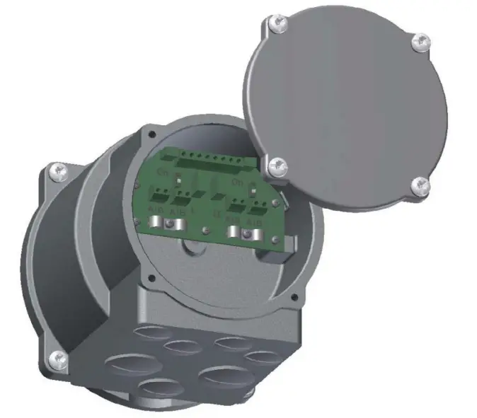
Connecting to Modbus RTU
Recommended Cable Confectioning
Prior to connection the bus lines are to be confectioned as seen in the Figure 2 below:
Figure 2
The clamps on the connection board are designed for a maximum line cross-section of 1.5 mm 2
. The line diameter has to be in the range of 5 to 8 mm.
Connecting to a Strand between Devices
Other devices are connected to the bus in front and behind of the new Slave-Device.
Line configuration:
Figure 3 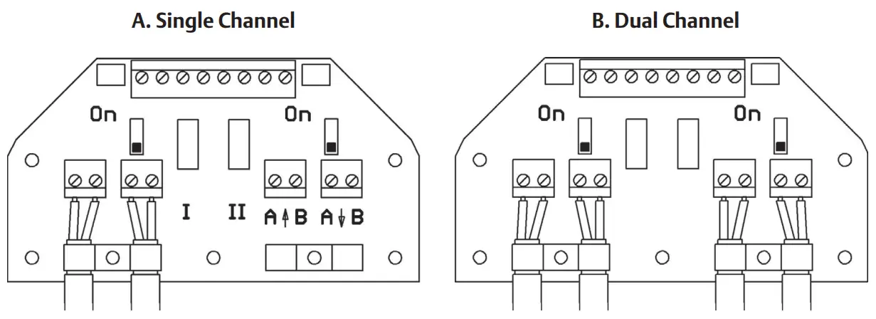
Connecting at the End of a Strand, Bus Termination
There is either no device connected to the bus in front or behind of the new Slave-Device.
Line configuration:
Figure 4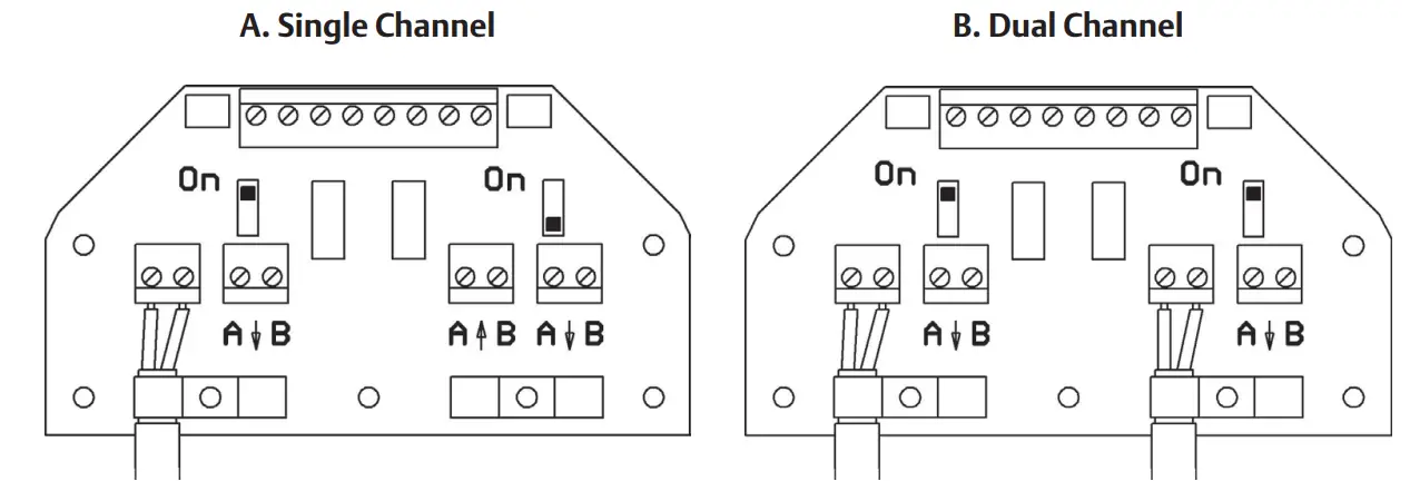
Bus termination:
Modbus RTU has to be terminated on both ends of every strand. Termination can be accomplished through the termination resistor implemented in your RTS control unit. Bus termination is activated when the respective switch on the connection board is switched to “ON” as seen in Figure 4 (A. Single Channel).
Explosionproof Design
Normally, in explosionproof design, there is no termination available in the control unit.
That means, the bus termination must be done seperate outside of the control unit.
Optionally, a bus termination in the control unit is possible as well, this must be specified by the order.
In this case, you can activate the bus termination by connecting the following terminals:
- A with AT and B with BT (single channel version) or
- A1 with A1T, B1 with B1T, A2 with A2T and B2 with B2T (dual channel version)
WARNING
The shield must be connected to the shielding connection clamp (windowcut), see Figure 5 or Figure 6.
Design with Binary Inputs and Outputs Figure 5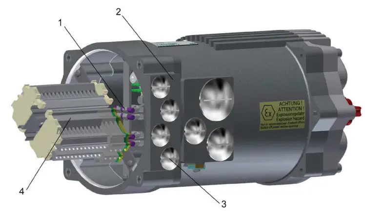
- Shielding connection clamp
- Additional frame
- Metallic cable glands (closed with blind screw connections at delivery) 4xM20x1.5
- Terminal strip
Design without Binary Inputs and Outputs Figure 6
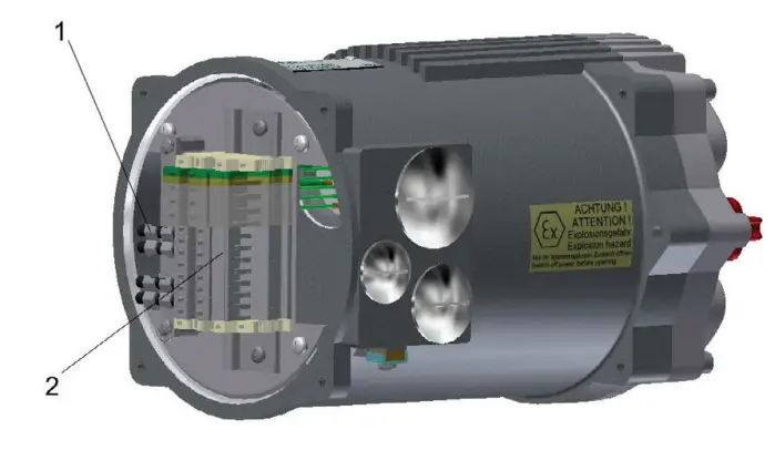
- Shielding connection clamp
- Terminal strip
An additional frame with 4xM20 holes is possible on special request.
Section 3: Setup
If Modbus RTU is activated, the following additional parameters will be visible in the control menu of your Bettis Electric Actuator. Each device connected to a Modbus RTU- network has to receive a unique address during setup.
Table 1.
| Menu item | Sub-item | Options | Explanation/Comments | |
| P15.1 | Modbus | Modbus | 0: not active | Modbus RTU deactivated. |
| 1: activated | Modbus RTU activated. | |||
| P15.2 | Modbus | Address Channel A | 0 bis 247 | Set the bus address of the first/primary channel. |
| P15.3 | Modbus | Address Channel B | 0 bis 247 | Set the bus address of the second/secondary channel (only for option “Modbus RTU redundant”). |
| P15.4 | Modbus | Watchdogtime | 0.0 -10.0 s [0.0 s] | Monitoring period of the togglebit. (Bit 7 in Master’s command). This bit has to toggle in the specified time or a buswatchdog error is detected. If Watchdogtime is set to 0.0 s, the watchdog is deactiveted. Toggling the respective bit can now be ommited. |
| P15.5 | Modbus | Setpoint Source | [0]: Standard | Setpoint specified by Modbus RTU (effective only if positioner is activated). |
| 1: Analog. | Setpoint specified by analogue signal (effective only if positioner is activated). | |||
| 2: Bus/Analog | Setpoint specified by Modbus RTU. In case of bus error, setpoint specified by analogue signal (effective only if positioner is activated). | |||
| P15.6 | Modbus | Status 2 | [0] | Standard value for Status 2. |
| 1 – 2 | Reserved for future use. | |||
| P15.7 | Modbus | Status 3 | [0] | Standard value for Status 3 (current event). |
| 1 – 2 | Reserved for future use. | |||
| P15.8 | Modbus | Status 4 | [0] | Standard value for Status 4. |
| 1 – 2 | Reserved for future use. |
Section 4: Specification of Input and Output Data
General requirement: Depending on the Master it is possible that the Lowbyte (Bit 0 – 7) and the High byte (Bit 8 – 15) are to be switched. Generally speaking, the mode of transmission (Big Endian / Little Endian) has to be set in a way that ensures the correct transmission of the analogue information. Only after this has been accomplished, the binary data can be transmitted.
Input Data Modules (Master to Slave Communication)
Input data can be handled with following Modbus functions:
Table 2.
Function
| 06 (06 hex) | Preset Single Register | Writes data to one single register in the slave. |
| 16 (10 hex) | Preset Multiple Registers | Writes data to multiple consecutively registers in the slave. |
| 03 (03 hex) | Read Holding Register | Reads back one single register from the slave. |
| 04 (04 hex) | Read Input Register | Reads back one single register from the slave. |
| 23 (17 hex) | Read/Write Multiple Registers | Writes data to multiple consecutively registers in the slave and reads multiple consecutively registers from the slave. If the reading and writing addresses the same egisters, a read back of the written data is performed. The write operation is performed before the read operation. |
Setpoint
Register number: 1, address 0000Hex
Data format: 16 bit, only the lowest 10 bit (0 – 1023) are in use.
Other bits are reserved for future use and have to be set to zero.
Table 3.
| Value | Function | Description |
| 0 (0Hex) | 0% | |
| 512 (200Hex) | 50% | |
| 1023 (3ffHex) | 100% |
Command
Register number: 2, address 0001Hex
Data format: 16 bit (Bitfield)
Table 4.
| Bit no. | Function | Description Bit=0 Bit=1 | |
| OPEN | – | OPEN in REMOTE mode. | |
| 1 | CLOSE | CLOSE in REMOTE mode. | |
| 2 | STOP | STOP in REMOTE mode. | |
| 3 | EMERGENCY-OPEN | EMERGENCY-OPEN in REMOTE and LOCAL mode. | |
| 4 | EMERGENCY-CLOSE | – | EMERGENCY-CLOSE in REMOTE and LOCAL mode. |
| 5 | BLOCK | Blocking the actuator in REMOTE and LOCAL mode. Actuator can neither be controlled through the switch on the device nor through commands over REMOTE nor Modbus RTU. | |
| 6 | POSITIONER OFF | – | Deactivating the positioner in REMOTE mode. |
| 7 | WATCHDOG | Togglebit for buswatchdog. Bit has to toggle before specified time-out or a buswatchdog error will be detected. | |
| 8 | OPEN-SH | Latched OPEN in REMOTE mode. Release with STOP. | |
| 9 | CLOSE-SH | Latched CLOSE in REMOTE mode. Release with STOP. | |
| 10 | LOCK-OPEN | Locks OPEN (in REMOTE and LOCAL mode) Actuator carries out a latched OPEN command with highest priority which can only be released with LOCK-OFF, power-off or mode OFF. | |
| 11 | LOCK-CLOSE | Locks CLOSE (in REMOTE and LOCAL mode) Actuator carries out a latched CLOSE command with highest priority which can only be released with LOCK-OFF, power-off or mode OFF. | |
| 12 | LOCK-OFF | Releases the lock. | |
| 13 | BLOCK LOCAL | Blocking the actuator in mode LOCAL. Actuator cannot be moved with selection switch. | |
| 14 | FAILSAFE | Trigger FAILSAFE-Unit (if available). | |
| 15 | OVERRIDE | Binary inputs will not be processed.c | |
Command 2
Register number: 3, address 0002Hex
Data format: 16 bit (Bitfield)
Table 5.
| Mee EQ, | Function , | Description | |
| Has (I) | Lets T | ||
| 0 | Bus Bit 1 | – | These binary outputs can be assigned to the bus. The assignment can be done arbitrarily, including the assignment of a single bit to mulitple outputs. (Available with Firmware 1.323) |
| 1 | Bus Bit 2 | – | |
| 2 | Bus Bit 3 | – | |
| 3 | Bus Bit 4 | – | |
| 4 | Bus Bit 5 | _ | |
| 5 | Bus Bit 6 | – | |
| 6 | Bus Bit 7 | – | |
| 7 | Bus Bit 8 | – | |
| 8 | reserved | – | Reserved for future use |
| 9 | reserved | – | |
| 10 | reserved | – | |
| 11 | reserved | – | |
| 12 | reserved | – | |
| 13 | reserved | – | |
| 14 | reserved | – | |
| 15 | reserved | – | |
Setpoint Revolution Speed
Register number: 4, address 0003Hex
Data format: 16 bit, only the lowest 8 bit (Bit 7: Direction OPEN; Bit 6 – 0 : 0 – 100 corresponding to 0 – 100%) are in use.
Other bits are reserved for future use and have to be set to zero.
Output Data Modules
(Slave to Master Communication)
Output data can be handled with following Modbus functions:
Table 6.
Function
| 03 (03 hex) | Read Holding Register | Reads one single register from the slave. |
| 04 (04 hex) | Read Input Register | Reads one single register from the slave. |
| 23 (17 hex) | Read/Write Multiple Registers |
Actual Position Value
Register number: 257, address 0100 Hex
Data format: 16 bit, only the lowest 10 bits (0 – 1023) are in use.
Other bits are reserved for future use and have to be set to zero.
Table 7.
| Value | Function | Description |
| 0 (0Hex) | 0% | |
| 512 (200Hex) | 50% | |
| 1023 (3ffHex) | 100% |
Status
Register number: 258, address 0101Hex
Data format: 16 bit (Bitfield)
Table 8.
| Bit no. | Function | Description | |
| Bit = 0 | Bit=1 | ||
| 0 | READY | – | Actuator is ready. |
| 1 | END POSITION OPEN | – | End position mode (torque OPEN reached or travel dependent)). (under consideration of switch-off |
| 2 | END POSITION CLOSE | – | End position mode (torque CLOSE reached or travel dependent)). (under consideration switch-off |
| 3 | TRAVEL OPEN | – | End travel mode (torque OPEN reached (under or travel dependent)). consideration of switch-off |
| 4 | TRAVEL CLOSE | – | End travel CLOSE reached (travel dependent). |
| 5 | TORQUE OPEN | – | Power-off torque in opening direction exceeded. |
| 6 | TORQUE CLOSE | – | Power-off torque in closing direction exceeded. |
| 7 | MOTORTEMP. | Motor temperature sensor signal (overheat). | |
| 8 | OPENING | – | Actuator moving in OPEN direction. |
| 9 | CLOSING | – | Actuator moving in CLOSE direction. |
| 10 | LOCAL | – | Switch in LOCAL mode position. |
| 11 | REMOTE | – | Switch in REMOTE mode position. |
| 12 | LOCK OPEN | – | Latched OPEN command with highest priority. (Refer to Command bit 10 und 12) |
| 13 | LOCK CLOSE | – | Latched CLOSE command with highest priority. (Refer to Command bit 10 und 12) |
| 14 | LIVEBIT 1 | Livebitl toggles with 1 Hz. | |
| 15 | LIVEBIT 2 | Livebit2 is a copy of the watchdog toggle-bit. (Refer to command Bit 7). | |
Actual Torque Value
Register number: 259, address 0102Hex
Data format: 16 bit, only the lowest 8 bit (Bit 7: Direction OPEN; Bit 6 – 0 : 0 – 100 corresponding to 0 – 100%) are in use.
Other bits are reserved for future use and have to be set to zero.
Actual Speed Value
Register number: 260, address 0103Hex
Data format: 16 bit, only the lowest 8 bit (Bit 7: Direction OPEN; Bit 6 – 0 : 0 – 100 corresponding to 0 – 100%) are in use.
Other bits are reserved for future use and have to be set to zero.
External Actual Value
Only with Option PID-Controller
Register number: 261, address 0104Hex
Data format: 16 bit, only the lowest 10 bit (0 – 1023) are in use.
Other bits are reserved for future use and have to be set to zero.
Status 2
Register number: 262, address 0105Hex
Data format: 16 bit (Bitfield)
Table 9.
Structure
| Bit no. | Function | ||
| Descripti n | |||
| Bit = 0 | Bit=1 | ||
| 0 | Dig. Output 1 | – | Corresponding binary output enabled. |
| 1 | Dig. Output 2 | – | |
| 2 | Dig. Output 3 | – | |
| 3 | Dig. Output 4 | – | |
| 4 | Dig. Output 5 | – | |
| 5 | Dig. Output 6 | – | |
| 6 | Dig. Output 7 | – | |
| 7 | Dig. Output 8 | ||
| 8 | Dig. Input 1 | – | Corresponding binary input enabled. |
| 9 | Dig. Input 2 | – | |
| 10 | Dig. Input 3 | – | |
| 11 | Dig. Input 4 | – | |
| 12 | Dig. Input 5 | – | |
| 13 | PHASE SEQUENCE | – | Phase Sequence Error: wrong phase order, phase failure, total failure, asymmetry. |
| 14 | FC ERROR | – | FC Error: Error in power supply or frequency converter (if present). |
| 15 | FAILSAFE ERROR | – | Failsafe-Unit not ready (if present). |
NOTE:
Using parameter P15.6 it is possible to assign alternative output-functions to “Status 2”.
Status 3
Register number: 263, address 0106Hex
Data format: 16 bit, error codes
Table 10.
| Error Code | Corresponds |
| 3 | Motor temperature warning. |
| 4 | Motor temperature power-off. |
| 5 | Phase order error or phase failure. |
| 9 | Power supply error or frequency converter error. |
| 11 | Failsafe-Unit error (if available). |
| 17 | Travel sensor error. |
| 22 | Torque sensor error. |
NOTE:
Using parameter P15.7 it is possible to assign alternative output-functions to “Status 3”.
Status 4
Register number: 264, address 0107Hex
Data format: 16 bit (Bitfield)
Reserved for future use.
NOTE:
Using parameter P15.8 it is possible to assign alternative output-functions to “Status 4”.
| NORTH & SOUTH AMERICA 19200 Northwest Freeway Houston TX 77065 USA T +1 281 477 4100 Av. Hollingsworth 325 Iporanga Sorocaba SP 18087-105 Brazil T +55 15 3413 8888ASIA PACIFIC No. 9 Gul Road #01-02 Singapore 629361 T +65 6777 8211 No. 1 Lai Yuan Road Wuqing Development Area Tianjin 301700 P. R. China T +86 22 8212 3300 | MIDDLE EAST & AFRICA P. O. Box 17033 Jebel Ali Free Zone Dubai T +971 4 811 8100 P. O. Box 10305 Jubail 31961 Saudi Arabia T +966 3 340 8650 24 Angus Crescent Longmeadow Business Estate East P.O. Box 6908 Greenstone 1616 Modderfontein Extension 5 South Africa T +27 11 451 3700EUROPE Holland Fasor 6 Székesfehérvár 8000 Hungary T +36 22 53 09 50 Strada Biffi 165 29017 Fiorenzuola d’Arda (PC) Italy T +39 0523 944 411 |
For complete list of sales and manufacturing sites, please visit www.emerson.com/actuationtechnologieslocations or contact us at [email protected]
www.emerson.com/bettis
VCIOM-16741-EN ©2021 Emerson. All rights reserved.
The Emerson logo is a trademark and service mark of Emerson Electric Co. BettisTM is a mark of one of the Emerson family of companies.
All other marks are property of their respective owners.
The contents of this publication are presented for informational purposes only, and while every effort has been made to ensure their accuracy, they are not to be construed as warranties or guarantees, express or implied, regarding the products or services described herein or their use or applicability. All sales are governed by our terms and conditions, which are available upon request. We reserve the right to modify or improve the designs or specifications of such products at any time without notice.


