FS NX N40 Series 8 Slot 2 Stackable DCI Platform
Introduction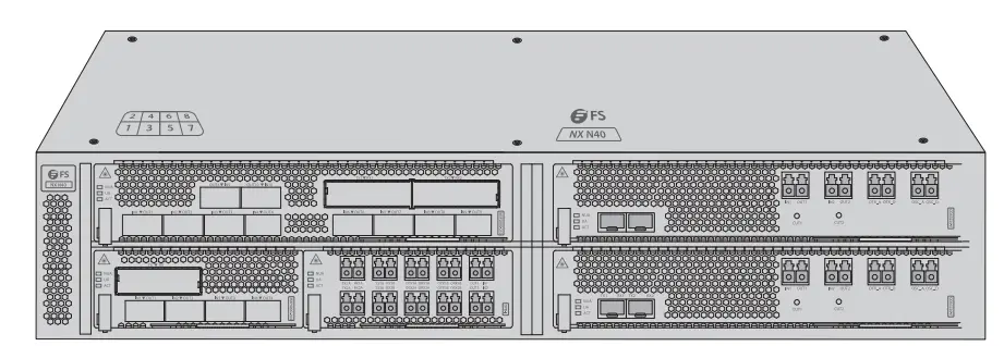
NX N40 Series DCI Platform provides a managed, flexible and scalable architecture for fiber networks. It can support ODA, OPB and MXP to construct a multi-service optical transmission network platform.
NX N40 Series Platform Overview
NX N40 Series Infrastructure Cards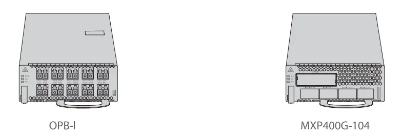
- Slot Card Type
- Slot Card Type
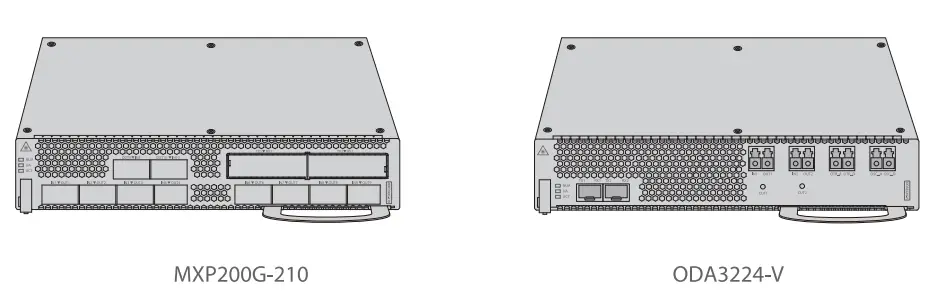
NOTE: 1. NX N40 Series DCI cards are designed as 1-slot card type or 2-slot card type to match the managed chassis. 2.1-slot card: OPB-, MXP400G-104;2-slot card: ODA3224-V, MXP200G-210.
Accessories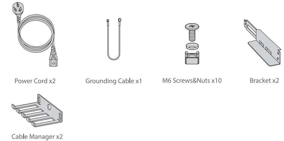
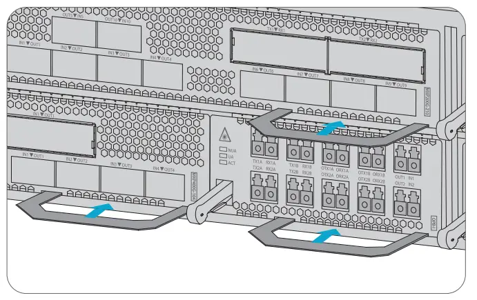
Hardware Overview
MXP200G-210 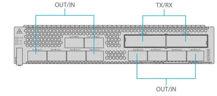
Front Panel Port
| OUT | Client-side optical interfaces | Transmit service signals to the client equipment. |
| IN | Client-side optical interfaces | Receive service signals from the client equipment. |
| TX | WDM-side optical interfaces | Transmit wavelength-specific optical signals to the optical multiplexer card. |
| RX | WDM-side optical interfaces | Receive wavelength-specific optical signals from the optical demultiplexer card. |
Front Panel LED
|
ACT | Blinking quickly | The card is activated. |
| Blinking slowly | The card is deactivated . | |
| ON | The card is working abnormally. Usually, the communication between the card and the EMS is poor. | |
| OFF | The card is working abnormally. Usually, the card is faulty. | |
| UA | ON | An urgent alarm occurs on the card. |
| OFF | No urgent alarm is reported or all urgent alarms are blocked. | |
| NUA | ON | A non-urgent alarm occurs on the card. |
| OFF | No non-urgent alarm is reported or all non-urgent alarms are blocked. |
ODA3224-V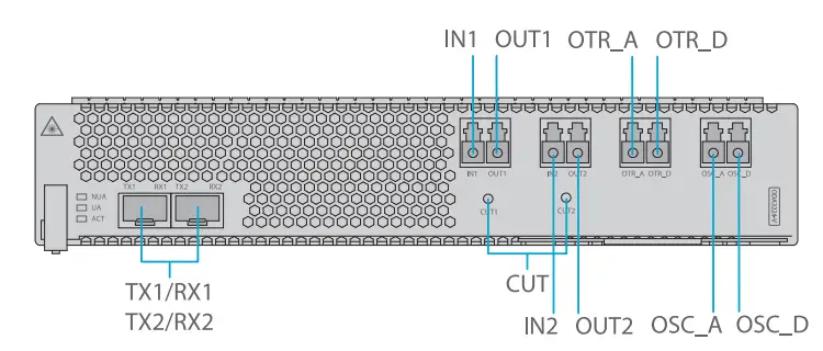
Front Panel Port
| IN1 | Input port for the optical path | Input optical port for optical signal channel 1. |
| OUT1 | Output port for the optical path | Output optical port for optical signal channel 1. |
| IN2 | Input port for the optical path | Input optical port for optical signal channel 2. |
| OUT2 | Output port for the optical path | Output optical port for optical signal channel 2. |
| OTR_A | Monitoring port for input Signals | Add port for the in-service test of external OTDR optical signals. |
| OTR_D | Monitoring port for output Signals | Drop port for the in-service test of external OTDR optical signals. |
| OSC_A | Monitoring port for input Signals | Add port for in-service tests of OSC optical signals; connected toTX1. |
| OSC_D | Monitoring port for output Signals | Drop port for in-service tests of OSC optical signals; connected to RX1. |
| TX2 | Output port for optical signals | Outputs OSC optical signals. |
| RX2 | Input port for optical signals | Inputs OSC optical signals. |
| TX1 | Output port for optical signals | Output OSC optical signals, connected to OSC_A. |
| RX1 | Input port for optical signals | Input OSC optical signals, connected to OSC_D. |
| CUT | Laser shutdown button | Pressing the button will turn off the card’s laser; releasing the button will turn on the laser. |
Front Panel LED
|
ACT | Blinking quickly | The card is activated. |
| Blinking slowly | The card is deactivated. | |
| ON | The card is working abnormally. Usually, the communication between the card and the EMS is poor. | |
| OFF | The card is working abnormally. Usually, the card is faulty . | |
| UA | ON | An urgent alarm occurs on the card. |
| OFF | No urgent alarm is reported or all urgent alarms are blocked. | |
| NUA | ON | A non-urgent alarm occurs on the card. |
| OFF | No non-urgent alarm is reported or all non-urgent alarms are blocked . |
OPB-I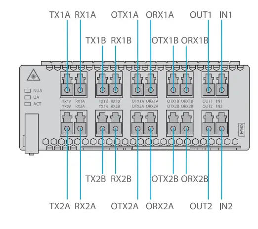
Front Panel Port
| TX1A | Tx interface for working signals | Transmit the 1st group working signals. |
| RX1A | Rx interface for working signals | Receive the 1st group working signals. |
| TX1B | Tx interface for protection signals | Transmit the 1st group protection signals. |
| RX1B | Rx interface for protection signals | Receive the 1st group protection signals. |
| TX2A | Tx interface for working signals | Transmit the 2nd group working signals. |
| RX2A | Rx interface for working signals | Receive the 2nd group working signals. |
| TX2B | Tx interface for protection signals | Transmit the 2nd group protection signals. |
| RX2B | Rx interface for protection signals | Receive the 2nd group protection signals. |
| OTX1A | Tx interface for OTDR signals | Indicate the OTDR optical interface for transmitting the 1st group working signals. |
| ORX1A | Rx interface for OTDR signals | Indicate the OTDR optical interface for receiving the 1st group working signals. |
| OTX1B | Tx interface for OTDR signals | Indicate the OTDR optical interface for transmitting the 1st group protection signals. |
| ORX1B | Rx interface for OTDR signals | Indicate the OTDR optical interface for receiving the 1st group protection signals. |
| OTX2A | Tx interface for OTDR signals | Indicate the OTDR optical interface for transmitting the 2nd group working signals. |
| ORX2A | Rx interface for OTDR signals | Indicate the OTDR optical interface for receiving the 2nd group working signals. |
| OTX2B | Tx interface for OTDR signals | Indicate the OTDR optical interface for transmitting the 2nd group protection signals. |
| ORX2B | Rx interface for OTDR signals | Indicate the OTDR optical interface for receiving the 2nd group protection signals. |
| INl | Input interface for to -be-protected signals | Input to-be-protected optical signals. |
| OUTl | Alternative signal output interface | Output optical signals . |
| IN2 | Input interface for to-be-protected signals | Input to-be-protected optical signals. |
| OUT2 | Alternative signal output interface | Output optical signals. |
Front Panel LED
|
ACT | Blinking quickly | The card is activated. |
| Blinking slowly | The card is deactivated. | |
| ON | The card is working abnormally. Usually, the communication between the card and the EMS is poor. | |
| OFF | The card is working abnormally. Usually, the card is faulty. | |
| UA | ON | An urgent alarm (critical or major alarm)occurs on the card. |
| OFF | No urgent alarm is reported or all urgent alarms are blocked. | |
| NUA | ON | A non-urgent alarm occurs on the card. |
| OFF | No non-urgent alarm is reported or all non-urgent alarms are blocked. |
MXP400G-104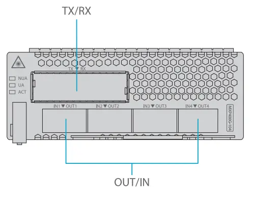
Front Panel Port
| OUT | Client-side optical port | Transmit service signals to the client equipment. |
| IN | Client-side optical port | Receive service signals from the client equipment. |
| TX | WDM-side optical port | Transmit wavelength-specific optical signals to the optical multiplexer card. |
| RX | WDM-side optical port | Receive wavelength-specific optical signals from the optical demultiplexer card. |
Front Panel LED
|
ACT | Blinking quickly | The card is activated. |
| Blinking slowly | The card is deactivated. | |
| ON | The card is working abnormally. Usually, the communication between the card and the EMS is poor. | |
| OFF | The card is working abnormally. Usually, the card is faulty. | |
| UA | ON | An urgent alarm occurs on the card. |
| OFF | No urgent alarm is reported or all urgent alarms are blocked . | |
| NUA | ON | A non-urgent alarm occurs on the card. |
| OFF | No non-urgent alarm is reported or all non-urgent alarms are blocked. |
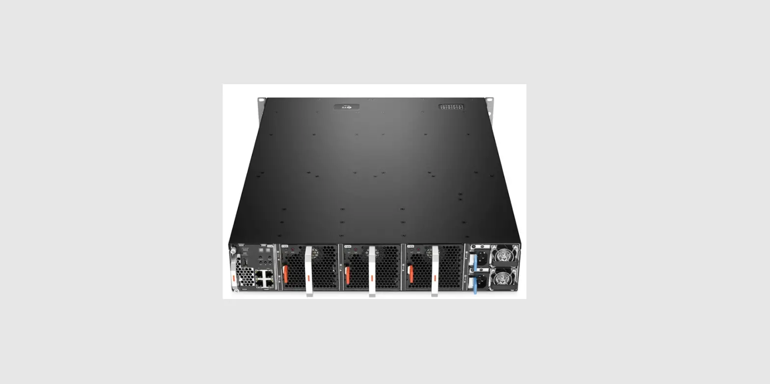
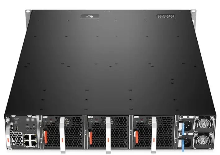
Managed Chassis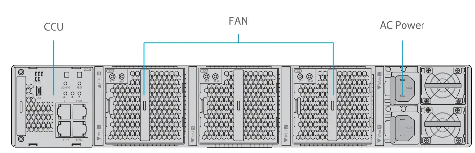
| CCU | Management plane&Electromechanical management function. |
| Fan | Heat Dissipation function. |
| AC Power | AC power supply. |
CCU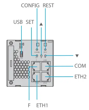
Front Panel Port
| CONFIG | Reserved button | Reserved. |
| USB | USB port | Back up cards’ logs, back up and upload system software, and quickly provision services through a U disk . |
| REST | Reset button | Pressing the button will reset the card. |
| SET | Reserved button | Reserved. |
|
LED digitron adjustment button | Manually adjust the LED digitron. Press this button, and the number is incremented by 1 (original function). After system upgrade, the CCU card reads the current subrack address through the intra-card signal and displays the address on the panel. In this case, this button is invalid. | |
|
T |
LED digitron adjustment button | Manually adjust the LED digitron. Press this button, and the number is decreased by 1 (original function). After system upgrade, this card reads the current subrack address through the intra-card signal and displays the address on the panel. In this case, this button is invalid. |
|
F |
EMS supervisory port | When the front subrack serves as a master suback, this interface enables communication between the equipment and the EMS and helps establish a supervisory channel.When the front subrack serves as a slave subrack, this interface is invalid. |
| COM | Software debugging port | Used for card debugging. |
| ETH1 |
Master-slave subrack cascading port | Cascade the master and slave subracks. An ETHl port should be connected to an ETHl port, and an ETH2 port should be connected to an ETH2 port. It is invalid to connect an “ETH1” port to an “ETH2″port. |
| ETH2 |
NOTE: LED digitron is displayed in two “8-bit’s. For example, 01, 02, or 03-99. These numbers identify the subracks, substituting paper labels.
Front Panel LED
| ACT | ON | The card is activated. |
| NUA | ON | A non-urgent alarm is reported for the card. |
| OFF | No non-urgent alarm is reported or all non-urgent alarms are blocked . | |
| DCC | Blinking | Datas are being received or transmitted in the corresponding DCC. |
FAN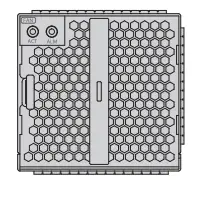
| ACT | ON | The power supply is connected. |
| OFF | The power supply is not well connected. | |
| ALM | ON | The fan unit is faulty. |
Site Environment
- Keep the enquipments indoors. If it is in rainy season or in humid environment, dehumidification measures must be taken.
- Ensure there is no water on the storage floor and no leakage to the packing box of the equipment.
- Avoid automatic fire fighting facilities, heating system and other places where leakage may occur.
Installing
Before installation, make sure that you have the followings:
- M6 Screws&Nuts
- Flat Screwdriver
- Cross Screwdriver
Installing a Card 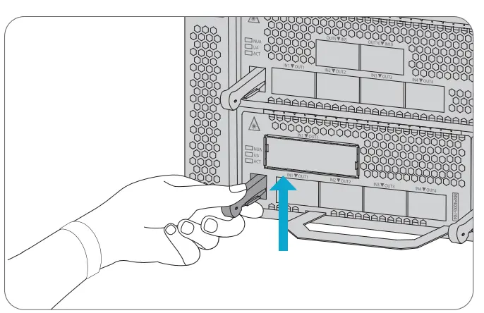
- Hold the card handle and align the left and right edges of the card with the internal slide rails.
- Push it in slowly along the internal slide rails until a “click” is heard, which indicates that the latch is locked.
Rack Mounting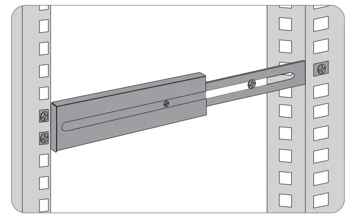
- Install the slide rails on the rack.
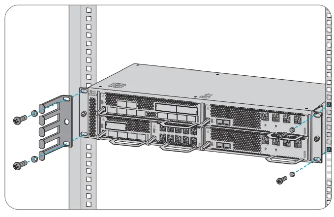
- Push the NX N40 series managed chassis into the rack along the slide rails.
- Use M6 screws&nuts to secure the chassis.
NOTE:
- The chassis to be mounted in the rack should be empty.
- Avoid collision or touching the fiber guide unit when carrying the chassis.
- The mounted chassis should be 130 mm away from the rack door before it.
Grounding the NX N40 Series Managed Chassis 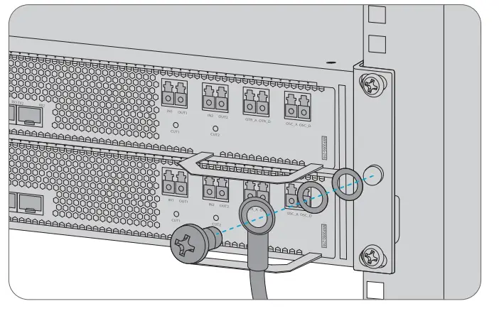
- Secure the grounding lug to the grounding point on the back panel of the chassis with screws and nut.
- Connect the other end of the cable to a proper earth ground point, such as the rack with the NX N40 series.
Connecting Power Cord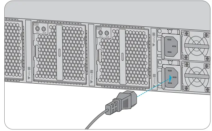
- Plug AC power cord into the power port on the back panel of the power card.
- Connect the other end of the power cord to an AC power source.
NOTE:
- Avoid the hybrid use of power cords from different vendors.
- Before connecting the chassis power cables, ensure that the external power supply is shut down. Never install the power cables while they are electrified.
- Make sure that the AC input power is cut off during the operation. Attach labels to the switches that will be used.
Connecting the Control Port 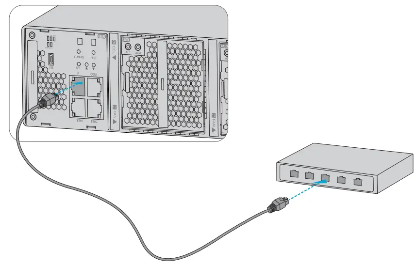
- Connect one end of the cable to the console port on the back panel.
- Connect the other end to a network port on the switch.
Configuring the NX N40 Series Platform
- Step 1: Install the netmanager software and refer to the Configuration Guide for detailed steps.
- Step 2: Enter the URL (Built-in IP address+8082/#/login. e.g. http://10.41.87.205:8082/#/login) on the web page to log in to the net manager software (Account: admin; Password: admin).
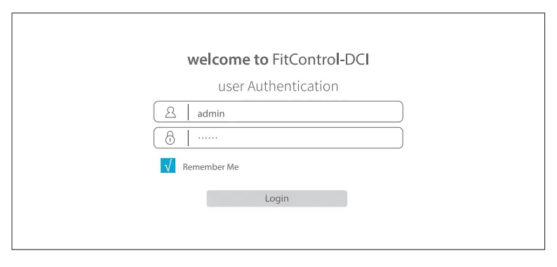
- Step 3: Click login, you are now ready to configure NX N40 Series Platform.
Troubleshooting
Card LEDs Working Abnormally
- Check the power cable connections at the NX N40 Series managed chassis and the power source.
- Make sure that all cables are used correctly and comply with the power specifications.
- Make sure that service cards are in the right position in the NX N40 Series managed chassis.
Accessing the Web-based Configuration Page Unsuccessfully
- Try another port on the CCU card and make sure the Ethernet cable is suitable and works properly.
- Power off the the NX N40 Series managed chassis and wait for a while, then power it on again.
- Make sure the built-in IP address is correctly configured.
- If you still cannot access the configuration page, please reinitialize the CCU server to its factory defaults.
Service Card Cannot Be Added
- Enter through CMD.
- Ping service card IP to check whether it can communicate.
- Check whether normal communication can be made between service card and the CCU card.
- Change another service card.
Online Resources
- Download https://www.fs.com/products_support.html
- Help Center https://www.fs.com/service/fs_support.html
- Contact Us https://www.fs.com/contact_us.html
Product Warranty
- Warranty: This product enjoys 2 years limited warranty against defect in materials or workmanship. For more details about warranty, please check at: https://www.fs.com/policies/warranty.html
- Return: If you want to return item(s), information on how to return can be found at: https://www.fs.com/policies/day_return_policy.html
References
 FS.com - Data Center, Enterprise, Telecom
-
Quality Certification - FS.com
-
Ein weltweit führender Anbieter von Hochgeschwindigkeits-Konnektivitätsgeräten und -lösungen. - FS.com Deutschland
-
Contact Us - FS.com
-
Kontakt - FS.com Deutschland
-
Rückgaberecht - FS.com Deutschland
-
Ein weltweit führender Anbieter von Hochgeschwindigkeits-Konnektivitätsgeräten und -lösungen. - FS.com Deutschland
-
Technische Dokumente - FS.com Deutschland
-
Hilfezentrum - FS.com Deutschland
-
Fournisseur leader de solutions et matériels de connectivité à haut débit - FS.com France
-
Comment Nous Contacter - FS.com France
-
Politique de retour - FS.com France
-
Fournisseur leader de solutions et matériels de connectivité à haut débit - FS.com France
-
Documents techniques - FS.com France
-
Centre d'aide - FS.com France
-
Return Policy - FS.com
-
Products Warranty - FS.com
-
Technical Documents - FS.com
-
Help Center - FS.com


