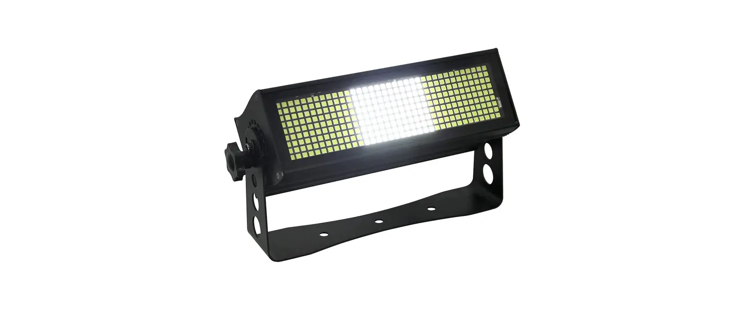
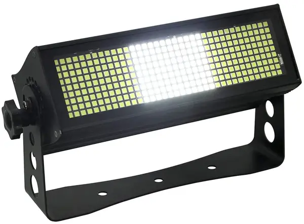
MEGA PAN T BOT Lite Tiltbot Trio
Check that the unit has not been damaged during transport
Read all cautions and warnings
prior to operation of this equipment
Protection Against Fire
- Maintain a minimum of 2 foot distance from any type of flame.
- For indoor use only do not expose unit to rain or moisture.
- Replace fuse only with the specified type and rating.
- Do not install the unit to close to a heat source.
- Make sure cable are properly secured
- Maximum surface operating temperature 130º.
Protection Against Electrical Fire
- Disconnect power before servicing.
- For connection to main power supply proceed to page 5.
- This unit must be earthed. (electronically grounded)
- This fixture must not be left on for long periods of time.
Protection Against Mechanical Hazards
- Use secondary safety chain when hanging unit.
- Use quality clamps or bolts when positioning unit
- Do not open unit while it is on, risk of electrical shock.
What is Included
- 1pc Pan T Bot Fixture
- 1pc Power Con (type) to Nema 5-15 Cable
- 2pc Quick Connect Clamp Mounts
- 1pc User Manual
Technical Information
Part Numbers
Fixture/ Road Case
1187-Pan T Bot CAS-1187-2 2 Unit Road Case
Mechanical Specifications
- Pan Angle: 540° 8/16 bit
- Tilt Angle: 270° 8/16 bit
- DMX Connectors: Panel Mounted 3 and 5-pin XLR connectors in/out
- Artnet Connection: Panel Mounted RJ45 In and Out
- Power Connections: Panel Mounted Power Conn (Type) Power in/out connection. (Nema 5-15 to Power Conn (Type) cable included)
- Thermal: Maximum ambient temperature 104°f Maximum surface temperature 140°f
- Display: Digital
- Fastening System: 2 Quick Connect Clamp Mount
- Lens Angle: 89° RGB Emitters, 40° White Emitters
Electrical Specifications
- LED: 960 RGB 0.5 Watts / 300 White 1 Watt (6670K)
- Lumen Output: 28,595lm (All Emitters)
- Power Input: Universal 100 – 240V 50/60 Hz
- Color Rendering: 6911K (White Center Emitter Only)
- Ballast: Electronic
Power Consumption:
- Watts: 590W
- Amps: 5.04A @110V
- RDM: Yes
Control & Programming
- Protocol: DMX 512
- RDM: Yes
- DMX Channels: 2 Modes of Operation
- Mode: 23 Ch: Pan, Pan Fine, Tilt , Tilt Fine, Pan and Tilt Speed, Dimmer, Red, Green, Blue, Strobe, Shutter Macro, Macro Speed, Color Macro, Macro Speed, Alpha numeric Display, Background Red, Background Green, Background Blue, White Dimmer, White Strobe, White Macro, Macro Speed, Control
- Mode: 256 Ch: Pan, Pan Fine, Tilt , Tilt Fine, Pan and Tilt Speed, Control, RGB X 80, White X 10.
- Operating Mode: Stand alone 255 step dimmer setting via display Auto preprogram via display
Main Power Connection
Caution!
- Do not connect fixture to a dimmer system.
- This unit has Auto switching power supply. It will respond to 110V or 240V automatically
- This unit must be earthed. (electronically grounded)
- Replace fuse only with the specified type and rating.
- Power Link max 3 units at 110V and 6 units at 220V.
The occupation of the connection-cable is as follows: This fixture is equipped with an electronic power supply that will let the unit operate from 100V to 240V from 50Hz to 60Hz
| Cable (USA) | Cable (EU) | Pin | 110V | 220V |
| Black | Brown | Live | L | L |
| White | Light Blue | Neutral | N | L |
| Green | Yellow/Green | Ground | N | L |
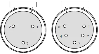
DMX-512 Connection
The fixture is equipped with 3 & 5 pin XLR cable mounted sockets for DMX input and output. The sockets are wired in parallel. Only use a shielded twisted pair cable designed for RS-485 3 and 5 pin XLR plugs and connectors in order to connect the controller with the fixture or the fixture with another
DMX—Input
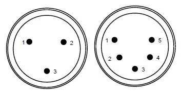
- Shield
- Signal (-)
- Signal (+)
- N/A
- N/A
DMX—Output
Caution!
At the last fixture the DMX signal needs to be terminated with a terminator. Solder a 120 Ohm re-sistor between the (-) and the (+) signal into a 3 or 5 pin XLR plug and plug it in to the last fixture on the signal run. Pre-manufactured terminator plugs are available for purchase from your Mega-Lite dealer (P-DMXT).
Segment Positions
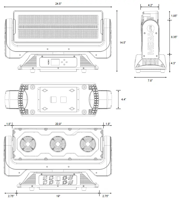
Size and Weight
| Size | 24.5″ X 7.6″ X 14.5″ |
| Weight | 36lb |
| Packaged | 28″ X 18″ X 11.5″ 38.6lb |
The control board on the fixture is your interface to access and control all the functions on the unit. Its digital display gives you a code view of the options and functions. The following will explain each function and its options
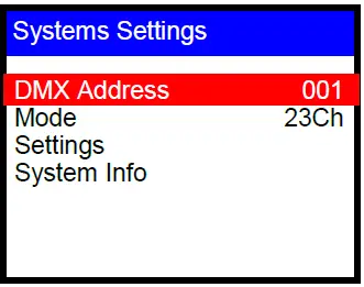
DMX Address
Press Home button. Use the up/down to select the DMX Address function press Enter to engage
 Use the up/down arrows to select the desired DMX start Channel. Please con-sult your DMX Controller’s Manual to find the correct DMX Start Channel 001
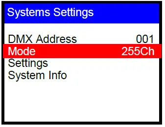
Mode
Press Home button. Use the up/down to select the Mode function press Enter to engage. Select from the 2 different operating modes.
DMX DMX 23Ch Auto PRO 01 SP 90 Manual Remote
- DMX: Allows you to select from the DMX Channel control method, Linebot offers 2 control methods Standard 15 Ch and Extended 63 Ch. Please select one
- Mode: 23 Ch: Pan, Pan Fine, Tilt , Tilt Fine, Pan and Tilt Speed, Dimmer, Red, Green, Blue, Strobe, Shutter Macro, Macro Speed, Color Macro, Mac-ro Speed, Alpha numeric Display, Background Red, Background Green, Background Blue, White Dimmer, White Strobe, White Macro, Macro Speed, Control
- Mode: 256 Ch: Pan, Pan Fine, Tilt , Tilt Fine, Pan and Tilt Speed, Control, RGB X 80, White X 10
- Auto: Allows you to select from the 17 preprogram patterns that are built into the fixture. It also allows you to control the speed of those programs from 01 to 99
- Manual: Allows you to control each of the fixtures functions via the display menu. Control from 000 to 255 for each func-tion (note if fixture is powered off and back on the fixture will return to the last set mode function)
- Remote: Fixture will copy the same functions as the Main unit. (Master Fixture must be in home screen setting to en-gage)
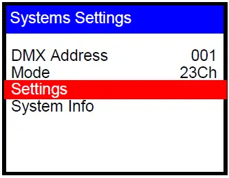
Settings
Press Home button. Use the up/down to select the Settings function press En-ter to engage. Select from the 5 different setting options.
Artnet Display On Display Rev Off Pan Rev N Tilt Rev N DMX Fail Bl Language
- Artnet: Please follow your lighting controllers instruction for artnet connection. As each controller has different procedure for connection. (note: Fixture has a maximum 16 universe setting) For Mega Control settings please set fixture to this setting:
IP Address- 002.168.052.253
- SubNet Mask
- 255.000.000.000
- Net 000 Subnet 000
- Universe 01
- Display: Display On will keep the display on for the entire time the fixtures is powered on. Display Off will auto- matically turn off the display if there is no changes after 30sec.
- Display Rev: Allows you to select from the 17 preprogram patterns that are built into the fixture. It also allows you to control the speed of those programs from 01 to 99
- Pan Rev: Inverts Pan Position
- Tilt Rev: Inverts Tilt Position
- DMX Fail: This function will allow you to set a default setting if the DMX signal is ever lost or stops working.
- Black Out: Will set all channel to 000 and turn light off
- Manual: Will go to the set position set on your manual display setting
- Auto: Will go to the selected Auto Preset and speed setting set in your auto option
- Hold: Will hold last DMX commend until a new command signal is received
- Language: Select ether English or Chinese
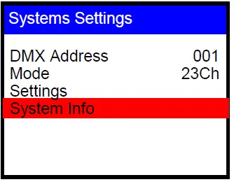
System Info
Press Home button. Use the up/down to select the System Info function press Enter to engage. Receive information on 3 different parameters
- Firmware: Gives you information on the software version being used in the fixture.
- Time Info: Provides information on the fixture usage, by counting the hours the fixture is powered on
- Temp: Gives you fixture internal temperature information
DMX Profile
Pan T Bot 23Channel Mode
| DMX Channel | Function | Description | Value | Init |
| 1 | Pan | Pan | 0-255 | 127 |
| 2 | Pan Fine | Pan Fine | 0-255 | 127 |
| 3 | Tilt | Tilt | 0-255 | 127 |
| 4 | Tilt Fine | Tilt Fine | 0-255 | 127 |
| 5 | Speed | Pan and Tilt Speed (fast to slow) | 0-255 | 0 |
| 6 | Dimmer | Dimmer (off to full) | 0-255 | 255 |
| 7 | LED Color | Red LED Intensity | 0-255 | 255 |
| 8 | LED Color | Green LED Intensity | 0-255 | 255 |
| 9 | LED Color | Blue LED Intensity | 0-255 | 255 |
|
10 | No Function | 0-1 |
0 | |
| Strobe (slow to fast) | 2-127 | |||
| Strobe | Strobe Pulse (slow to fast) | 128-170 | ||
| RGB | Random Strobe All (slow to fast) | 171-213 | ||
| Random 1-80 Strobe (slow to fast) | 214-255 | |||
|
11 | No Function | 0-1 |
0 | |
| Macro 1 | 2-12 | |||
| Macro 2 | 13-23 | |||
| Macro 3 | 24-34 | |||
| Macro 4 | 35-45 | |||
| Macro 5 | 46-56 | |||
| Macro 6 | 57-67 | |||
| Macro 7 | 68-78 | |||
| Macro 8 | 79-89 | |||
| Macro 9 | 90-100 | |||
| Macro 10 | 101-111 | |||
| Shutter Macro | Macro 11 | 112-122 | ||
| (Select Color) | Macro 12 | 123-133 | ||
| Macro 13 | 134-144 | |||
| Macro 14 | 145-155 | |||
| Macro 15 | 156-166 | |||
| Macro 16 | 167-177 | |||
| Macro 17 | 178-188 | |||
| Macro 18 | 189-199 | |||
| Macro 19 | 200-210 | |||
| Macro 20 | 211-221 | |||
| Macro 21 | 222-232 | |||
| Macro 22 | 232-255 | |||
| 12 | Macro Speed | Shutter Macro Speed (slow to fast) | 0-255 | 0 |
|
13 |
Multy Color Macro | No Function | 0-1 |
0 |
| Macro 1 | 2-12 | |||
| Macro 2 | 13-23 | |||
| Macro 3 | 24-34 | |||
| Macro 4 | 35-45 | |||
| Macro 5 | 46-56 | |||
| Macro 6 | 57-67 | |||
| Macro 7 | 68-78 | |||
| Macro 8 | 79-89 | |||
| Macro 9 | 90-100 | |||
| Macro 10 | 101-111 | |||
| Macro 11 | 112-122 | |||
| Macro 12 | 123-133 | |||
| Macro 13 | 134-144 | |||
| Macro 14 | 145-155 | |||
| Macro 15 | 156-166 | |||
| Macro 16 | 167-177 | |||
| Macro 17 | 178-188 | |||
| Macro 18 | 189-199 | |||
| Macro 19 | 200-210 | |||
| Macro 20 | 211-221 | |||
| Macro 21 | 222-232 | |||
| Macro 22 | 232-255 | |||
| 14 | Macro Speed | Color Macro Speed (slow to fast) | 0-255 | 0 |
|
15 | No Function | 0-1 |
0 | |
| 0 | 2-6 | |||
| 1 | 7-12 | |||
| 2 | 13-18 | |||
| 3 | 19-24 | |||
| 4 | 25-30 | |||
| 5 | 31-36 | |||
| 6 | 37-52 | |||
| 7 | 43-48 | |||
| 8 | 49-54 | |||
| 9 | 55-60 | |||
| A | 61-66 | |||
| B | 67-72 | |||
| C | 73-78 | |||
| D | 79-84 | |||
| E | 85-90 | |||
| F | 91-96 | |||
| G | 97-102 | |||
| H | 103-108 | |||
| Alpha Numeric | I | 109-114 | ||
| Display | J | 115-120 | ||
| K | 121-126 | |||
| L | 127-132 | |||
| M | 133-138 | |||
| N | 139-144 | |||
| O | 145-150 | |||
| P | 151-156 | |||
| Q | 157-162 | |||
| R | 163-168 | |||
| S | 169-174 | |||
| T | 175-180 | |||
| U | 181-186 | |||
| V | 187-192 | |||
| W | 193-198 | |||
| X | 199-204 | |||
| Y | 205-210 | |||
| Z | 211-216 | |||
| Right Arrow | 217-222 | |||
| Down Arrow | 223-228 | |||
| Up Arrow | 229-234 | |||
| Left Arrow | 235-255 | |||
| 16 | Back Red | Background Red | 0-255 | 0 |
| 17 | Back Green | Background Green | 0-255 | 0 |
| 18 | Back Blue | Background Blue | 0-255 | 0 |
| 19 | White Dimmer | White | 0-255 | 255 |
|
20 |
Strobe | No Function | 0-1 |
0 |
| Strobe (slow to fast) | 2-127 | |||
| Strobe Pulse (slow to fast) | 128-170 | |||
| Random Strobe All (slow to fast) | 171-213 | |||
| Random 1-10 Strobe (slow to fast) | 214-255 | |||
|
21 | No Function | 0-1 |
0 | |
| Macro 1 | 2-19 | |||
| Macro 2 | 20-39 | |||
| Macro 3 | 40-59 | |||
| Macro 4 | 60-89 | |||
| White Macro | Macro 5 | 90-109 | ||
| (Responds to | Macro 6 | 110-139 | ||
| White Dimmer) | Macro 7 | 140-159 | ||
| Macro 8 | 160-189 | |||
| Macro 9 | 190-209 | |||
| Macro 10 | 210-239 | |||
| Macro 11 | 240-255 | |||
| 22 | Macro Speed | White Macro Speed (slow to fast) | 0-255 | 0 |
| 23 | Control | No Function | 0-127 | 0 |
| Reset | 128-255 | |||
Pan T Bot 256 Ch Mode
| DMX Channel | Function | Description | Value | Init |
| 1 | Pan | Pan | 0-255 | 127 |
| 2 | Pan Fine | Pan Fine | 0-255 | 127 |
| 3 | Tilt | Tilt | 0-255 | 127 |
| 4 | Tilt Fine | Tilt Fine | 0-255 | 127 |
| 5 | Speed | Pan and Tilt Speed (fast to slow) | 0-255 | 0 |
| 6 | Control | No Function | 0-127 | 0 |
| Reset | 128-255 | |||
| 7 | LED Color | White 1 | 0-255 | 0 |
| 8 | LED Color | White 2 | 0-255 | 0 |
| 9 | LED Color | White 3 | 0-255 | 0 |
| 10 | LED Color | White 4 | 0-255 | 0 |
| 11 | LED Color | White 5 | 0-255 | 0 |
| 12 | LED Color | White 6 | 0-255 | 0 |
| 13 | LED Color | White 7 | 0-255 | 0 |
| 14 | LED Color | White 8 | 0-255 | 0 |
| 15 | LED Color | White 9 | 0-255 | 0 |
| 16 | LED Color | White 10 | 0-255 | 0 |
| 17 | LED Color | Red 1 | 0-255 | 0 |
| 18 | LED Color | Green 1 | 0-255 | 0 |
| 19 | LED Color | Blue1 | 0-255 | 0 |
| 20 | LED Color | Red 2 | 0-255 | 0 |
| 21 | LED Color | Green 2 | 0-255 | 0 |
| 22 | LED Color | Blue 2 | 0-255 | 0 |
| ” “ | ” “ | ” “ | ” “ | |
| 251 | LED Color | Red 79 | 0-255 | 0 |
| 252 | LED Color | Green 79 | 0-255 | 0 |
| 253 | LED Color | Blue 79 | 0-255 | 0 |
| 254 | LED Color | Red 80 | 0-255 | 0 |
| 255 | LED Color | Green 80 | 0-255 | 0 |
| 256 | LED Color | Blue 80 | 0-255 | 0 |
Item List
| Part Number | Description |
| 1187-BEZ-ARM | Arm Plastic Housing |
| 1187-BEZ-BAS | Base Plastic Housing |
| 1187-BEZ-HAN | Handel Plastic Housing |
| 1187-BEZ-HEA | Rear Head Plastic Housing |
| 1187-BEZ-LEN | Front Head Plastic Housing |
| 1187-BEZ-YOK | Yoke Plastic Housing (single piece) |
| 1187-FAN-60 | 60mm Fan |
| 1187-FAN-90 | 90mm Fan |
| 1187-LED-MOD-RGB | Led Module RGB |
| 1187-LED-MOD-WHI | Led Module White |
| 1187-LED-RGB | Single LED RGB |
| 1187-LED-WHI | Single LED White |
| 1187-MOT-PAN | Pan Motor |
| 1187-MOT-TIL | Tilt Motor |
| 1187-PCB-DRI-WHI | LED PCB for White Driver |
| 1187-PCB-MAI | Main PCB |
| 1187-PCB-VOL | Voltage Distribution PCB |
| 1187-POW | Power Supply |
| CAS-1187-2 | Dual Road Case |
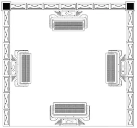
Rigging the Fixture
Caution!
- The installations must be carried out by an authorized dealer or trained professional.
- Unit may cause severe injuries if you have doubts concerning the safety do not install.
- Unit is to be 24inches away from flammable materials (decoration material)
- Use high quality installation equipment to hang unit
When rigging a unit it is very important that you follow common safety procedures. Rigging requires extensive experi-ence including but not limited to calculating working loads, material being used and periodic safety inspections. If you lack these qualifications, do not attempt the installation yourself, instead use a professional structural rigger.
When rigging the unit always be secured with a secondary safety attachment. The installation location of the projector has got to be built in the way that it can hold 10 times the weight for 1 hour with out any harming. Installation should be checked at least once a year by a skilled person
Unit can be installed in any of these directions
Cleaning and Maintenance
Installation Maintenance: The operator has to make sure that the unit is operating safely and has the installations and electronics checked by an expert every 2 years
The following points have to be considered during the inspection:
- All screws used for installing the device or part of the device have to be tightly connected and must not be corroded.
- There must not be any deformations on the housing, fixation and installation spots (ceiling, suspension, trussing).
- The electronic power supply cables must not show any damages, material fatigue (e.g. porous cables) or sediments. Further instructions depending on the installation spot and usage have to be adhered by a skilled installer and any safety problems have to be removed
Note: There is no serviceable parts inside the device. Maintenance and service operations are to be carried out by au-thorized dealers.
Replacing the fuse: When possible only replace the fuse with the same type and rating.
Replacing the power cable: If the power cable of this device becomes damaged, it has to be replaced by authorized dealers or trained professional only. Should you have further questions , please contact your dealer
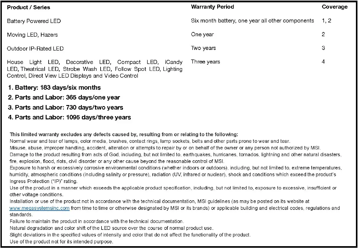
MEGA Systems, Inc. Warranty
MEGA SYSTEMS INC (“MSI) hereby warrants to the original purchaser/owner (‘Customer), MSI products to be free of manufacturing defects in material and workmanship, tor the warranty periods as defined below from the original purchase invoice date. I his warranty applies exclusively to new MSI branded andlor distributed products listed below, purchased from an MSl AUTHORIZED dealer/ reseller. This warranty is not transferable and may or may not apply to products sold and/or forwarded outside the United States. Please contact MSI for applicable regional product warranty information. The purchase of MS product constitutes the Customer’s acceptance of all warranty terms and conditions as listed in this limited warranty statement This warranty provides the Customer with legal rights, which may vary from state to state. Please contact MSI regarding warranty questions prior to purchasing
All warranty claims are evaluated under the terms of this limited waranty. If a product falls within the warranty period and if, upon examination by MSl it is found to have tailed for a covered cause, MSI will, at ts sole discretion, repair or replace the defective part or product or reimburse the purchaser a pro-rated portion of the purchase price based on the percentage of the warranty period still remaining as of the date that the returned product was received by MSI. Should a replacement part or product be discontinued or unavallable, MS reserves the nght, in ts sole and absolute discretion, to substitute a comparable replacement part or product for the defective pat or product. MSI warranty obligation hereunder is limited solely to the repair or replacement of or reimbursement tor the particular parts or products determined by MSI to have Tailed for a covered cause within the warranty period.
In no event shall MSI be responsible to replace or reimburse purchaser for any products or portions of a system that MsI determines has not failed for a covered cause within the warranty period, even it such other productsS or portions of a system are used together with products being repaired or replaced by MSI under this warranty and the repaired product difers in brightness, colors or any other attribute after the repai. Costs of removal, shipping to MSI or its authorized representative and reinstallation are solely the respon sibility of the purchaser. If MSI determines that the product is covered by this imited warranty, It WIl only pay tor parts and labor as Indicated Dy product type. IT Ms determines that the product is not covered by thiS limited warranty, the purcnaser will nave the option ot paying Tor the repair (IT the product can be repaired) and the purcnaser shall be responsible Tor the cost or shipping the repaired pr0duct back TO the purchaser. MSI reserves the rignt, In is sole and absoure aiscreuon, to decline any repair.
IN NO EVENT SHALL MEGA SYSTEMS, INC. BE LIABLE FOR ANY INCIDENTAL, CONSEQUENTIAL, SPECIAL, INDIRECT OR PUNITIVE LOSS OR
DAMAGE OF ANY KIND, INCLUDING, BUT NOT LIMITED TO, LOSS OF PROFITS OR REVENUES, LOSS OF USE OF THE PRODUCT OR ANY OTHER GOODS OR ASSOCIATED EOUIPMENT, DAMAGE TO ANY ASSOCIATED EQUIPMENT, COST OF CAPITAL, COST OF SUBSTITUTE PRODUCTS, FACILITIES OR SERVICES, DOWN TIME COST, INSTALLATION OR LABOR cOSTS, OR CLAIMS OF THE PURCHASER’S CUSTOMERS, WHETHER BASED ON WARRANTY, CONTRACT OR NEGLIGENCE, ARISING IN CONNECTION WITH THE SALE, USE OR REPAIR OF THE PRODUCT. MEGA SYSTEMS INC’S MAXIMUM LIABILITY SHALL NOT, IN ANY CASE, EXCEED THE PURCHASE PRICE OF THE PRODUCT THAT GIVES RISE TO THE CLAIM. EXCEPT FOR THE LIMITED WARRANTY SET FORTH HEREIN, ALL PRODUCTS SOLD BY MEGA SYSTEMS, INC. ARE SOLD “AS IS’ WITHOUT ANYWARRANTY, EXPRESS OR IMPLIED, STATUTORY OR OTHERWISE, INCLUDING, BUT NOT LIMITED TO, IMPLIED WARRANTIES OF MERCHANTABILITY AND FITNESS FOR A PARTCULAR PURPOSE, ALL OF WHICH ARE EXPRESSLY AND SPECIFICALLY DISCLAIMED BY MEGA SYSTEMS, INC.
Customer Support
Mega Lite has a customer support line to provide set up help and to answer any question should you encounter a prob-lem. Please visit our website for any other related technical documents. For service related issue please contact our service dept.
- Monday—Friday 9am to 6pm CST
- Phone: 210-684-2600
- E-mail: [email protected]
Manual Version
Please Visit www.mega.lighting for the most up to date manual version
- Document Version 1.0
- Date 01/10/2023
- Fixture Software V1.0
- Notes
Mega-Lite 18668 Highway 16N Helotes, Texas 78023 Ph 210-684-2600 Fax 210-855-6279 www.mega.lighting / [email protected]


