unicorecomm UM220-IV L Copyright 2009-2021 Unicore Single Frequency Multi GNSS Timing Module
Product Information
UM220-IV L Single Frequency Multi-GNSS
Timing Module
The UM220-IV L is a single-frequency multi-GNSS timing module manufactured by Unicore Communications, Inc. It is designed for use by technical personnel with expertise in GNSS receivers.
Features
- Single-frequency GNSS timing capability
- Multi-GNSS support
- RESET time sequence
- TIME PULSE output
- Compact design
Technical Specifications
The technical specifications of the UM220-IV L are:
| Parameter | Value |
|---|---|
| Frequency | L1 |
| Channels | 72 |
| Position Accuracy | 2.5m CEP |
| Time Accuracy | 30ns RMS (1PPS) |
| Voltage Range | 2.7V to 5.5V (VCC), 1.5V to 5.5V (V_BCKP) |
Installation
Prerequisites:
- The UM220-IV L module
- A power supply (VCC)
- An antenna
Instructions
- Connect the power supply (VCC) to the module.
- Connect the antenna to the module.
- Make sure the RESET time sequence is properly configured.
- Verify that the TIME PULSE output is operating as expected.
Revision History
| Version | Revision History | Date |
| R1 | Initial version | 2020-01-06 |
| R1.1 | Update the range of VCC and V_BCKP | 2021-08-31 |
| R1.2 | Add the Note in Section 4.2 | 2021-11-17 |
Disclaimer
This manual provides information about the products of Unicore Communications, Inc. This document does not transfer the patent, trademark, copyright of the company or any third party, or any right or permission under it by implication, estoppel or otherwise.
Except as stated in the sales terms and conditions of the products, the company shall not assume any other responsibilities. Furthermore, Unicore Communications, Inc. makes no warranty, express or implied, for the sale and/or use of its products, including the suitability of a particular purpose and marketability of products, or liability for infringement of any patent, copyright or other intellectual property rights. If the connection or operation is not in accordance with the manual, the company is not liable. Unicore Communications, Inc. may make changes to product specifications and product descriptions at any time without prior notice.
The company’s products may contain certain design defects or errors, which will be included in the corrigendum once found, and may therefore result in differences between the products’ actual specifications and the published ones. Updated corrigendum is available upon request.
Before placing an order, please contact our company or local distributors for the latest specifications.
* Unicore Communications, UNICORECOMM, UFirebird and its logo have been applied for trademark registration by Unicore Communications, Inc.
Other names and brands are the property of their respective owners.
© Copyright 2009-2021 Unicore Communications, Inc. All rights reserved.
Foreword
This document describes the product features and information of the hardware design, installation, specification and the use of UNICORECOMM UM220-IV L module.
Audience
This manual is created for the technical personnel, who possess the expertise of GNSS receivers.
Product Introduction
Overview
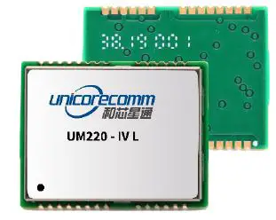
UM220-IV L is a GNSS multisystem, high-precision timing module, based on the low power, multisystem, high-performance SoC-UFirebird independently developed by UNICORECOMM. It supports GPS, BDS, GLONASS and Galileo, etc. Moreover, it is capable to receive and process data of two or three systems concurrently, or work on a single system.
UM220-IV L module supports SBAS, QZSS and DGNSS input function, and provides the advanced AGNSS function. It can improve the positioning speed through the assistant data service of UNICORECOMM in the scenario of networking.
With the combined function of filter, linear amplifier and antenna protection, and optimized RF architecture and interference rejection capability, UM220-IV L module provides the reliable performance in complex electromagnetic environments.
UM220-IV L module supports various timing modes including fixed-location timing, optimized-location timing and positioning timing, which ensure the good timing accuracy even in complex signal environmental conditions.
UM220-IV L module features compact dimensions, SMT PADS, full-automatic integration of standard pick-and-place and reflow soldering, and is especially suitable for low-cost, low-power applications.
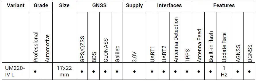
Features
Table 1- 1 Product Feature
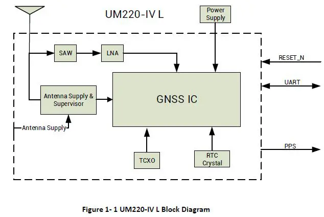
Block Diagram
Performance
Table 1- 2 Specifications
| Power | |||||
| Voltage | 3.0~3.6VDC | ||||
| Power Consumption1 | 62mW @3.3V | ||||
| RF Input | |||||
| VSWR | ≤2.0 | ||||
| Input Impedance | 50Ω | ||||
| Antenna Gain | 5~35dB | ||||
| Physical Characters | |||||
| Dimensions | 17.0mm*22.4mm*2.4mm | ||||
| Weight | 1.7g | ||||
| Environment | |||||
| Operating Temperature | -40℃ ~ +85℃ | ||||
| Storage Temperature | -40℃ ~ +85℃ | ||||
| RoHS2.0 | Compliant | ||||
| Input/ Output Data Interface | |||||
| UART | UART*2, LVTTL. Baud Rate: 4800~115200 bps | ||||
| GNSS Performance | |||||
| Constellations | BDS B1: 1561.098MHZ GPS L1: 1575.42MHZ GLONASS L1OF: 1602MHZ Galileo E1-B/C: 1575.42MHZ | ||||
| TTFF2 (Time to First Fix) | Cold Start: 28s Hot Start: 1s Reacquisition: 1s AGNSS3: 4s | ||||
| Positioning Accuracy (CEP)4 | 2.0m (Horizontal) 3.5m (Vertical) | ||||
| Velocity Accuracy (RMS)5 | 0.1m/s (Horizontal) | ||||
| Sensitivity6 | GPS | BDS | GLONASS | Galileo | |
| Cold Start | -147dBm | -144dBm | -142dBm | -135dBm | |
| Tracking | -160dBm | -160dBm | -158dBm | -154dBm | |
| Hot Start | -155dBm | -151dBm | -150dBm | -143dBm | |
| Reacquisition | -155dBm | -151dBm | -150dBm | -140dBm | |
| 1PPS (RMS)7 | 20ns | ||||
| Data Update Rate | 1Hz | ||||
| Format | NMEA 0183,Unicore Protocol,RTCM3.2 | ||||
- Continuous positioning, typical value
- All satellites C/N0 at 41
- Assisted data injection in time
- All satellites C/N0 at 41
- All satellites C/N0 at 41
- Tested with a good external LNA
P recision Timing and Raw Data Output
UM220-IV L module supports three timing modes: fixed-location timing, optimized-location timing and positioning timing. Switch or query the above timing modes through CFGTM. It can also track all four GNSS systems including GPS, BDS, GLONASS and Galileo, and switch back and forth between these four systems using CFGGNSS.
UM220-IV L module is set to optimized-location timing mode by default, and outputs information of real-time position and site-specific position, which can be queried by TIMPPOS. Refer to UM220-IV L_Protocol Specification for more details.
- Fixed-location Timing
Fixed-location timing mode is applied to static scenes. In this mode, users are required to input the exact position of receiver antenna center through CFGTM manually, which are used by UM220-IV L module to calculate the distance between the antenna and the satellite, and calculate time to perform timing service. - Optimized-location Timing
Optimized-location timing mode is another application used in static scenes. In this mode, the receiver collects a set number of positioning points (within observation time) and calculates the exact position of the antenna. After that, the exact position is locked down, and the timing mode is switched to the fixed-location timing mode.
The observation time and accuracy are configured through CFGTM, but only when both above-mentioned conditions are met to use fixed-location timing mode. Query the observation status through TPFINFO.
The position estimation process is only required once after the UM220-IV L is installed. When the position optimization is completed, the timing mode set in the receiver automatically switches to the fixed-location timing mode.
If the position of UM220-IV L antenna changes, the command CFGTM must be sent again to switch the timing mode back to the optimized position mode to recalibrate the antenna position. Refer to UM220-IV L_ Protocol Specification for more details. - Positioning Timing
Positioning timing is the only timing mode that supports dynamic timing. In this mode, UM220-IV L calculates the antenna position and time in real time. The timing quality depends on the satellite environment, and it is difficult to guarantee the timing accuracy.
Pulses per Second (1PPS)
UM220-IV L module provides a pulse width output and 1PPS signal of which the pulse polarity is adjustable, and can be configured and queried through CFGTP. TIMTP is used to describe the related 1PPS information including the corresponding time and time accuracy indicators.
UART
Two UART interfaces are integrated in the UM220-IV L module. UART1 is the master serial port, supports data transmission and firmware upgrade, the I/O signal type is LVTTL. The Default Baud rate is 115200bps and the baud rate can be configured by users. Please ensure that UART1 is connected to a PC or external processor to support firmware upgrade.
Serial 2 only supports data transmission and is unavailable for firmware upgrade, only for backup.
Protocol
Table 1- 3 Supported Interface Protocols
| Protocol | Type |
| NMEA0183 | I/O, ASCII, NMEA3.0, NMEA4.1(Default output) |
| Unicore Protocol | I/O, ASCII, Unicore Protocol |
| RTCM8 | Input, RTCM3.2 |
Refer to UM220-IV L_Protocol Specification for more details
Clock
The industrial TCXO is built into the UM220-IV L module to ensure the stability of the clock system and the ability to capture signals quickly in weak signal environments.
UM220-IV L also integrates the 32k crystal to maintain the RTC clock. When the main power supply is removed, the normal operation of the RTC can be maintained by providing V_BCKP.
Antenna
The filter and linear amplifier are built in the UM220-IV L module. They support active antennas and passive antennas, and the former provides better performance.
Product Installation
Prerequisites
Most components on the UM220-IV L module are static sensitive devices (SSD) and require ESD protection for IC circuits and other devices. Perform the following protection measures before opening antistatic plastic boxes.
- Perform the steps in section 2.2 Installation in the correct order;
- Electrostatic discharge (ESD) may cause a damage to the device. All operations referred to in this section should be performed on an ESD workbench using wrist straps and conductive foam pads. If there is no anti-static workbench, wear wrist straps and connect their other ends to the metal frame to avoid electrostatic damages;
- Hold the edge of the module, do NOT touch the components directly;
- Carefully check the module for any apparent loose or damaged components. If there are any questions, please contact Unicore or the local distributors.
Figure 2- 1 Typical Installation of UM220-IV L shows the typical installation of the UM220-IV L EVK.
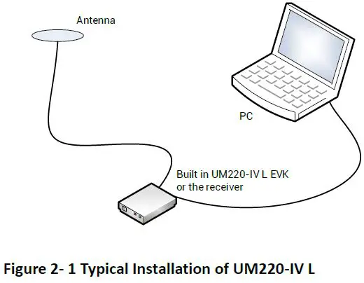
Have the following accessories ready before starting the installation:
- UM220-IV L EVK (including a power supply)
- UM220-IV L User Manual
- uSTAR_L executable file
- Qualified GNSS antennas
- Antenna cable
- Straight-through cable
- Desktop or laptop computer with serial port and installed with uSTAR_L
Please keep the packing box and anti-static box for storage and handling.
Installation
Follow the below steps to install UM220-IV L and EVK.
Step 1. Ensure adequate anti-static measures, such as wrist straps, workbench grounding, etc.
Step 2. Open UM220-IV L EVK suite, and take out the evaluation board.
Step 3. Select the GNSS antenna with the appropriate gain (the system frequency supported by the antenna should be consistent with the module) , fix it in the non-occluded area, and use the appropriate cable to connect the antenna and the UM220-IV L EB (evaluation board);
Step 4. Connect the PC to the EVK serial port using a straight-through cable.
Step 5. Power on the evaluation board and initialize UM220-IV L.
Step 6. Open the uSTAR_L software.
Step 7. Configure the receiver through uSTAR to display constellations view,messages, and receiver status, etc.
Product Technical Specifications
Electrical Specifications
Table 3- 1 Absolute Maximum Ratings
| Parameter | Symbol | Min | Max | Units | Condition |
| Power Supply Voltage | VCC | -0.5 | 3.6 | V | |
| VCC Maximum Ripple | Vrpp | 0 | 50 | mV | |
| Backup Power Supply Voltage | V_BCKP | -0.5 | 3.6 | V | |
| Antenna Bias Voltage | V_ANT | 6 | V | ||
| VCC_RF Voltage | VCC_RF | 3.6 | V | ||
| Input Pin Voltage | Vin | -0.5 | VCC+0.2 | V | |
| Storage Temperature | Tstg | -40 | 85 | ℃ | |
| Maximum ESD Stress | VESD (HBM) | 500 | V |
Operating Conditions
Table 3- 2 Operating Conditions
| Parameter | Symbol | Min | Typical Value | Max | Units | Condition |
| Power Supply Voltage | VCC | 3.0 | 3.3 | 3.6 | V | |
| Peak Current | Iccp | 100 | mA | VCC=3.0V | ||
| Backup Power Supply Voltage | V_BCKP | 1.65 | 3.6 | V | ||
| Antenna Bias Voltage | V_ANT | 2.8 | 5.5 | V | ||
| VCC_RF Voltage | VCC_RF | VCC-0.1 | V | |||
| Low Level Input Voltage | Vin_low | 0.2*VCC | V | |||
| High Level Input Voltage | Vin_high | 0.7*VCC | V | |||
| Low Level Output Voltage | Vout_low | 0.4 | V | Iout=8mA | ||
| High Level Output Voltage | Vout_high | VCC– 0.4 | V | Iout=8mA | ||
| Antenna Gain | Gant | 5 | 35 | dB | ||
| Noise Figure | Nftot | 4 | dB | |||
| Operating Temperature | Topr | -40 | 85 | ℃ |
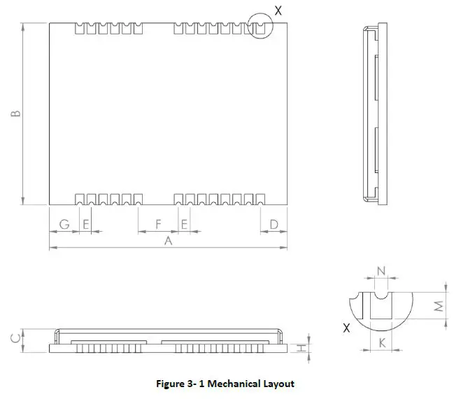
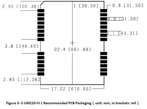
Mechanical Specifications
Table 3- 3 Dimensions
| Parameter | Min (mm) | Typical Value (mm) | Max (mm) |
| A | 22.1 | 22.4 | 23.0 |
| B | 16.9 | 17.0 | 17.1 |
| C | 2.1 | 2.4 | 2.7 |
| D | 2.45 | 2.55 | 2.85 |
| E | 1.0 | 1.1 | 1.2 |
| F | 3.7 | 3.8 | 3.9 |
| G | 2.75 | 2.85 | 3.15 |
| H | 0.82 | ||
| K | 0.7 | 0.8 | 0.9 |
| M | 0.9 | 1.0 | 1.1 |
| N | 0.4 | 0.5 | 0.6 |
Pin Definition
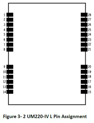
Table 3- 4 Pin Definition
| No | Name | I/O | Electrical Level | Description |
| 1 | TXD2 | O | LVTTL | COM2 is for data transmission. Firmware upgrade is not supported. Leave this pin floating if idle. |
| 2 | RXD2 | I | LVTTL | COM2 is for data transmission. Firmware upgrade is not supported. Leave this pin floating if idle. |
| 3 | TXD1 | O | LVTTL | COM1 is for data transmission. Firmware upgrade is supported. |
| 4 | RXD1 | I | LVTTL | COM1 is for data transmission. Firmware upgrade is supported. |
| 5 | NC | |||
| 6 | VCC | I | 3.0V~3.6V | Power supply |
| 7 | GND | Ground | ||
| 8 | VCC_OUT | O | 3.0V~3.6V | Power supply output, leave this pin floating if idle |
| 9 | NC | |||
| 10 | nRESET | I | LVTTL | External Reset Pin, low active |
|
11 |
V_BCKP |
I |
1.65V~3.6V | When the main power supply VCC of the module is cut off, V_BCKP supplies power to RTC and SRAM; Current value is about 50μA V_BCKP is necessary for hot-start, leave this pin floating if idle. |
| 12 | NC | |||
| 13 | GND | — | Ground | |
| 14 | GND | — | Ground | |
| 15 | GND | — | Ground | |
| 16 | RF_IN | I | GNSS signal input | |
| 17 | GND | — | Ground | |
| 18 | VCC_RF | O | 3.0V~3.6V | RF power supply output, leave this pin floating if idle |
| 19 | V_ANT | I | Antenna bias voltage, ground this pin if idle | |
| 20 | ANT_DET_N | I | LVTTL | Open circuit detection of the active antenna |
| 21 | NC | |||
| 22 | NC | |||
| 23 | NC | |||
| 24 | NC | |||
| 25 | NC | |||
| 26 | NC | |||
| 27 | NC | |||
| 28 | TIME PULSE | O | LVTTL | 1PPS, leave this pin floating if idle |
When designing PCB solder mask, make sure that the area under UM220-IV l module is completely coated with solder mask.
Hardware Design
Power Supply VCC
VCC is the main power supply of UM220-IV L module, which requires a good monotonic function when powering up, while undershoot and ringing should be guaranteed within 5% VCC. For the VCC to be powered back on after a power failure, the power failure time must exceed 10ms. If the VCC power supply does not meet the requirements described above, there is a certain probability that the module will not start properly
Antenna Design
- Passive Antenna
The RF input port of the module can be connected directly to the RF_IN without providing a DC voltage. There are a few things to note when using a passive antenna:- Select a proper installation position of the antenna to reduce the interference of electromagnetic noise, so as to enable the optimum performance of the antenna;
- A 50 impedance match of RF link is needed;
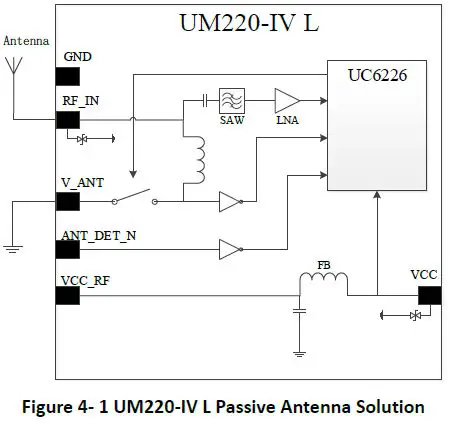
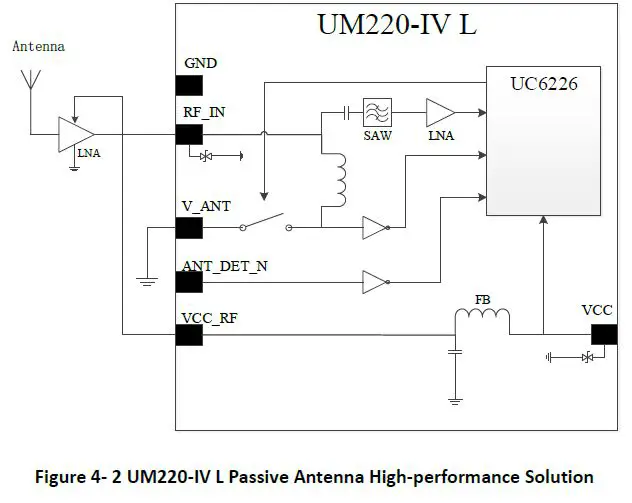
To improve the performance of RF analog front-end, a low noise amplifier (LNA) can be added behind the passive antenna. UM220-IV L module provides a 3.3V power supply (VCC_RF) for LNA.
Note: If the user has a high requirement for ESD (higher than the maximum specification in User Manual), the user should consider other method to power the LNA rather than using the VCC_RF pin. In this case, it is recommended to choose a power supply chip with high ESD protection level. Gas discharge tube, varistor, TVS tube and other high-power protective devices may also be used in the power supply circuit to further protect the module from ESD damage or other Electrical Over-Stress (EOS).
Active Antenna
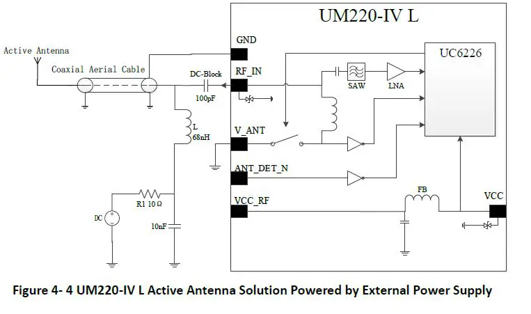
The active antenna increases the system power consumption when improving the system performance. The 3.3V Power Supply (VCC_RF) provided by the UM220-IV l module can be used to power the antenna directly if the function of detecting the state of the antenna inside the module is not used and the working voltage of the antenna is 3.3V.
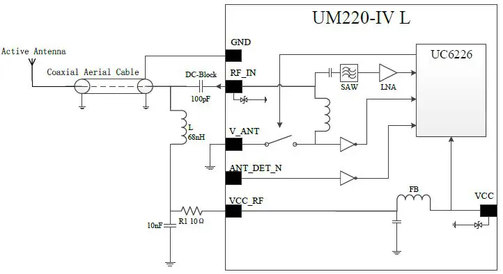
Figure 4- 3 UM220-IV L Active Antenna Solution Powered by VCC_RF
Note: If the user has a high requirement for ESD (higher than the maximum specification in User Manual), the user should consider other method to feed the antenna rather than using the VCC_RF pin. In this case, it is recommended to choose a power supply chip with high ESD protection level. Gas discharge tube, varistor, TVS tube and other high-power protective devices may also be used in the power supply circuit to further protect the module from ESD damage or other Electrical Over-Stress (EOS).
When the working voltage of the active antenna is not 3.3V, the antenna can be powered by the external power supply.
Active Antenna State D etection
UM220 IV L module can detect the active antenna state including open circuit, short circuit and normal state. The host computer enables or disables the antenna state detection function by transmitting commands via serial ports, and receives the detected antenna state via serial ports. The module cuts off the power supply automatically when detecting the short circuit state of antenna.
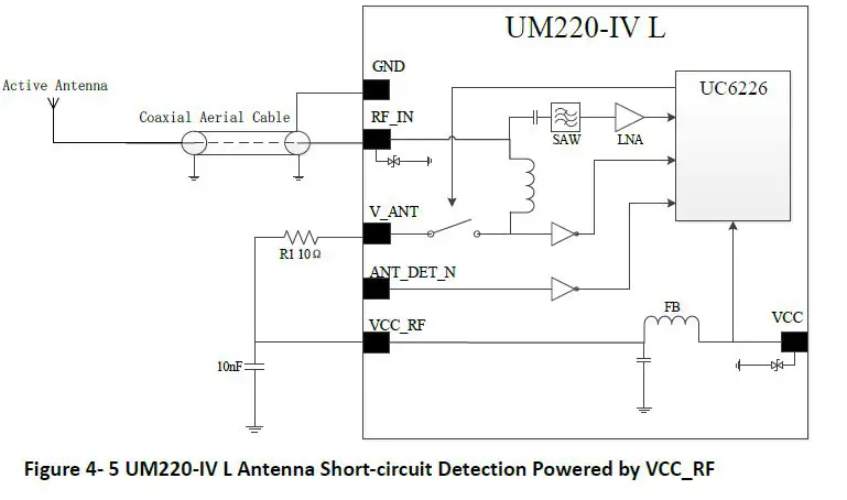
- Antenna Short circuit Detection
If the antenna short circuit detection function is required , connect the antenna power supply to t he module’s V_ANT Pin after cascading an appropriate value of resistance,and feed the antenna through the i nternal switch. If the V_ANT pin is directly connected without a seri al resistor, the module will be damaged when the antenna is short circuited. The internal switch is turned off by default, which can be switched with the CFGANT command
When the module d etects an antenna short circuit, the antenna feed is cut off immediately through the internal switch, periodically feeds the antenna and detects the state. Use ANTSTAT for the query.
If the working voltage of the antenna is 3.3V, the 3.3V power supply (VCC_RF) provided by the module can be connected in series with a 10Ω resistor to the V_ANT pin, and turn on the internal switch through CFGANT to power the antenna. If an antenna short c circuit is detected at this time, the module will automatically turn off the switch. When there is a need to save the power consumption, turn off the switch through CFGANT
Refer to UM220-IV L_ Protocol Specification for more details
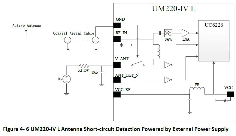
When the working voltage of the antenna is 5V, the antenna can be powered by connecting an external power supply with a 10Ω serial resistor to the V_ANT pin. Since this power supply is directly connected to the RF_IN pin of the module, this power supply cannot introduce noise. It’s recommended to use the power supply from analog network.
- Antenna Shot-circuit and Open-circuit Detection
If the short-circuit and open-circuit detection functions of the module are required concurrently, use the ANT_DET_N pin to cooperate with an external circuit. The threshold current for open circuit detection can be calculated by formula (4-1). When the antenna working current is less than the calculated value, the module determines that the antenna is open-circuit. The resistance of the series resistor R1 can be adjusted according to the antenna working current.
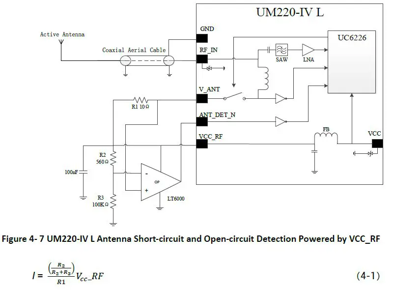
If an external power supply is used to power the antenna, the maximum power supply voltage cannot exceed 5.5V to protect the ANT_DET_N pin,Use ANTSTAT to query the antenna state.
UART
The two serial ports of UM220-IV L are LVTTL levels, which need to be converted through RS232 level if connected to PC.
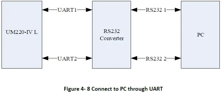
It is recommended that users reserve a test point for serial port 2 as the debug port.
If there is data input on the module input ports (RXD, GPIO) when the module is not powered on, it will form a string of electricity voltage on the module VCC. When the string voltage is higher than 1.6V, it may cause a start failure when the module is powered on. To prevent the string power, ensure that the IO port connected to the module is in high impedance or low level when the module is not powered on.
RESET Time Sequence
There is a reset chip inside the module. When VCC is lower than 2.63V (typical value of ambient temperature) or nRESET is at low level, the module is in reset state. After VCC rises to 2.63V or nRESET changes from low to high, the reset state of the chip will continue to remain for 200ms.
It is recommended to keep the reset signal of the nRESET pin for 10ms after VCC is valid at power-up. During normal operation, the minimum valid time of the reset signal for the nRESET pin is 500ns.
TIME PULSE Output
The period of the TIME PULSE output signal is 1s, the peak-to-peak value is VCC, and the default duty cycle is 10%.
Layout Recommendation
- Power supply: Stable and low ripple power is necessary for good performance.
Make sure the peak to peak voltage ripple does not exceed 50mV.- Use LDO to ensure the purity of power supply
- Place LDO to the module as close as possible in layout;
- Widen the power circuit wiring or use split copper surface to transmit current;
- Avoid the high power or high inductance devices such as magnetic coil.
- Antenna interface: note with the antenna impedance matching, and the circuit is short and smooth, try to avoid acute angle s .
- Connect the RF signal to the antenna and make sure the 50 Ω impedance match on the circuit.
- Antenna location: to obtain a good signal to noise ratio, ensure that the antenna is well isolated from electromagnetic radiation sources, esp ecially electromagnetic radiation in the frequency range of 1559 to 1605 MHz.
- Try to avoid circuits below the UM220 IV L module
- UM220 IV L module is a temperature sensitive device, rapid temperature changes wil l result in reduced performance. Keep it as far away from the high power high temperature air and heating devices as possible.
Packaging
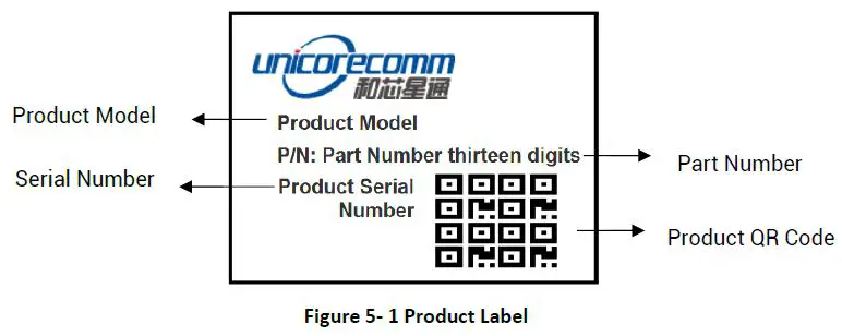
Product Labeling
Packaging Description
UM220IV L modules use carrier tape and reel (suitable for mainstream surface mount equipment), packaged in vacuum sealed aluminum foil antistatic bags, with a desiccant inside to prevent moisture. When using reflow welding process to weld mod ules, please strictly comply with IPC standard to conduct humidity control on modules. As packaging materials such as carrier belt can only withstand the temperature of 65 degrees Celsius, modules shall be removed from the packaging during baking.
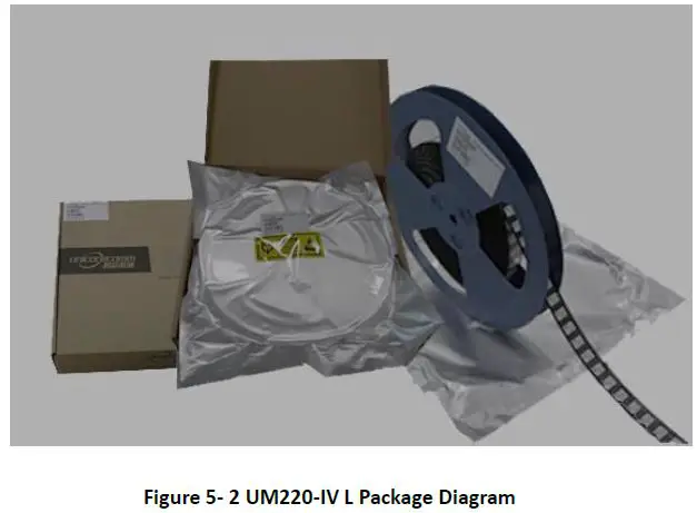
Table 5- 1 Package Instructions
| Item | Description |
| Module | 500 pics/reel |
|
Reel size | tray:13″ external diameter: 330mm, internal diameter: 100mm, width: 24mm thickness: 2.0mm |
| Carrier tape | Space between: 20mm |
UM220I V L module is rated at MSL level 3, refer to the relevant IPC/JEDEC standards for baking requirements. Please access to the website www.jedec.org to download for details.
The shelf life of UM220 IV L module is one year.
Soldering and Disassembly
Disassembly
When it is necessary to remove the module, it is recommended to melt the soldering tin of the pins on both sides of the module with anelectric soldering iron and remove the module with tweezers. D o NOT use other means to remove the module (for example, the module is blown off by a hot air gun), which may lead to module damage.
Clean
Do NOT use alcohol or other organic solvents to clean, it may lead to fluk residues into the shielding shell, causing mildew and other problems
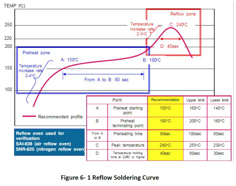
Reflow Soldering
In order to avoid component falling off, the module should be placed on the upper part of the motherboard when soldering . The reflow temperature curve is recommended as shown in figure 6 1 below (M705 GRN360 is recommended for solder paste
Note: The module can only be soldered onc e.
Unicore Communications, Inc.
F3, No.7, Fengxian East Road, Haidian, Beijing, P.R.China,100094
www.unicorecomm.com
Phone: 86-10-69939800
Fax: 86-10-69939888
[email protected]


