unicorecomm UM621N Series Module User Manual
Revision History
| Version | Revision History | Date |
| R1.0 | First release | Oct. 2022 |
Legal right notice
This manual provides information and details on the products of Unicore Communication, Inc. (“Unicore”) referred to herein.
All rights, title and interest to this document and the information such as data, designs, layouts contained in this manual are fully reserved, including but not limited to the copyrights, patents, trademarks and other proprietary rights as relevant governing laws may grant, and such rights may evolve and be approved, registered or granted from the whole information aforesaid or any part(s) of it or any combination of those parts.
Unicore holds the trademarks of “和芯星通”,“UNICORECOMM” and other trade name, trademark, icon, logo, brand name and/or service mark of Unicore products or their product serial referred to in this manual (collectively “Unicore Trademarks”).
This manual or any part of it, shall not be deemed as, either expressly, implied, by estoppel or any other form, the granting or transferring of Unicore rights and/or interests (including but not limited to the aforementioned trademark rights), in whole or in part.
Disclaimer
The information contained in this manual is provided “as is” and is believed to be true and correct at the time of its publication or revision. This manual does not represent, and in any case, shall not be construed as a commitments or warranty on the part of
Unicore with respect to the fitness for a particular purpose/use, the accuracy, reliability and correctness of the information contained herein.
Information, such as product specifications, descriptions, features and user guide in this manual, are subject to change by Unicore at any time without prior notice, which may not be completely consistent with such information of the specific product you
purchase.
Should you purchase our product and encounter any inconsistency, please contact us or our local authorized distributor for the most up-to-date version of this manual along with any addenda or corrigenda.
Foreword
This document describes the information of the hardware, installation, specification and the use of Unicore UM621N modules.
Document Structure
- Product introduction
- Installation guide
- Technical specifications
- Package
- Clean
- Reflow soldering
Introduction
Overview
UM621N is a GNSS dual-frequency module with MEMS integrated navigation. It is designed for automotive applications based on the multi-system, dual-frequency and high-performance GNSS SoC – UFirebird II (UC6580A), which is independently developed by Unicore Communications, Inc. With the built-in six-axis inertial navigation device, the module supports multi-system dual-frequency joint positioning and single system standalone positioning, and can output GNSS+MEMS combined positioning results continuously even in tunnels and underground garages.
The chip of UM621N conforms to the requirements of AEC-Q100, and the manufacturing process is in line with IATF 16949.
| Model | Order ing Code | PN | Grade | System | Interface | Data UpdateRate | ||||||||||
| Professional | Automotive | GPS | BDS | GLONASS | Galileo | NAVIC* | QZSS | SBAS | UART1 | UART2 | I2C | SPI | ||||
| UM621N | 02 | 2310414000008 | ● | ● | ● | ● | ● | ● | ● | ● | ● | ● | ● | ● | 1Hz/10Hz/20Hz* | |
* The default data update rate is 1Hz, which can be configured to 10 Hz or 20 Hz, and the 20 Hz needs to be supported by specific firmware.
* NAVIC is supported by specific firmware.
Key Specifications
Power
| Voltage | +2.7 V~3.6 V DC |
| Power Consumption | 330 mW |
RF Input
| Constellations | GPS/GLONASS/BDS/Galileo/QZSS/NAVIC (IRNSS)* |
| Standing Wave Ratio | ≤2.5 |
| Input Impedance | 50 Ω |
| Antenna Gain | 15 dB ~ 30 dB |
Physical Characteristics
| Dimensions | 16.0 mm*12.2 mm*2.4 mm |
Environmental Specification
| Operating Temperature | -40 ˚C ~ +85 ˚C |
Input/ Output Data Interface
| UART x 2 | LVTTL levelSupported baud rate: 115200 ~ 460800 bps |
| I2C x 1 | Address: 7 bitOperating in slave mode Transfer rate: 400 Kbps |
| SPI x 1 | Alternate function of pin 18~21 Operating in slave mode Maximum transfer rate: 4 Mbps |
GNSS Performance
| Frequencies | GPS L1 C/A, L1C*, L5 GLONASS L1BDS B1I, B1C*, B2aGalileo E1, E5a NAVIC* L5 QZSS L1, L5 SBAS | |
| Time to First Fix (TTFF) | Cold StartHot Start Reacquisition | 30s2s 2s |
| Horizontal Positioning Accuracy | 1.5 m CEP (dual-frequency quad-constellation, open sky) | |
| Velocity Accuracy (RMS) | 0.1 m/s | |
| INS Positioning Error | 3D gyro + 3D accelerometer + speed signal 2% | |
| Sensitivity | GNSS | |
| Tracking | -165 dBm | |
| Acquisition | -148 dBm | |
| Hot Start | -158 dBm | |
| Reacquisition | -160 dBm | |
| GNSS Data Update Rate | 1 Hz / 10 Hz* | |
| INS Data Update Rate | 100 Hz | |
| 1PPS Accuracy (RMS) | 20 ns | |
| Data Format | NMEA 0183, Unicore Protocol | |
* Items marked with an asterisk are supported by specific firmware.
Interfaces
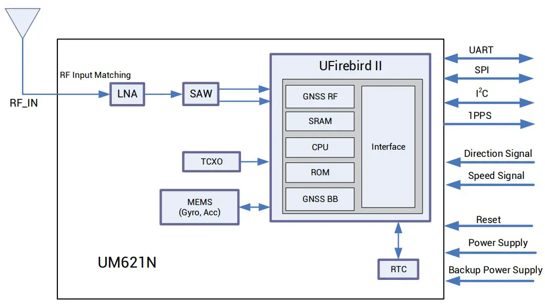
Figure 1-1 UM621N Block Diagram
UART
UART1 is the main serial port of UM621N, supporting data transmission and firmware upgrade, and the signal input/output voltage level is LVTTL. The baud rate can be configured by users flexibly, and the maximum is 460800bps. Ensure that UART1 is connected to a PC or an external processor for firmware upgrade.
UART2 only supports data transmission and can’t be used for firmware upgrade.
MEMS
UM621N integrates a six-axis MEMS, a three-axis gyro and a three-axis accelerator.
MEMS provides information on carrier attitude and speed changes, combined with
GNSS data to output integrated positioning and navigation solution. The combination of GNSS+MEMS ensures better positioning performance than standalone GNSS, providing continuous and uninterrupted positioning, especially in the conditions with poor signals, such as tunnels, underground garages and urban canyons.
1PPS
UM621N outputs 1PPS with adjustable pulse width and polarity.
1PPS is not for timing application.
nRESET
Active LOW, and the active time should be no less than 10 ms.
Product Installation
Preparations
UM621N modules are Electrostatic Sensitive Devices (ESD) and must be installed with special precautions when handling. Please take the following protective measures before opening the anti-static plastic box
- Follow the steps in section 2.2 in the correct order.
- Electrostatic discharge (ESD) may cause damage to the device. All operations mentioned in this chapter should be performed on an antistatic workbench, using an antistatic wristband and a conductive foam pad. If the antistatic workbench is unavailable, wear an antistatic wristband and connect the other end to a metal frame to play a role in antistatic protection.
- Hold the edge of the module, and DO NOT touch any components of the module.
- Please check carefully whether the module is obviously loose or damaged. If there are any problems, please contact Unicore or the local dealer.
Figure 2-1 shows the typical installation of UM621N evaluation kit (EVK).
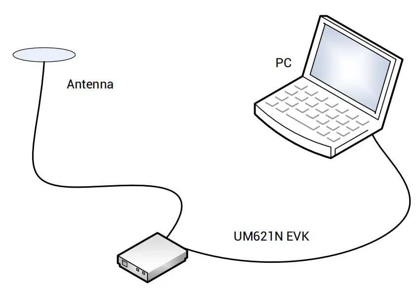
Figure 2-1 Typical Installation of UM621N
Please prepare the following items before installing UM621N.
- UM621N EVK (with AC Adapter)
- UM621N User Manual
- Unicore uSTAR software package
- Ancillary GNSS antenna
- USB cable and straight through serial cable
- PC or Laptop with serial ports (Windows 7 and above)
Please keep the packing box and anti-static plastic box for storage and handling.
Hardware Installation
After the above preparations, please follow the steps below to install, which is used for satellite navigation test only.
Step 1: Make sure to take full anti-static measures, such as wearing an anti-static wristband and grounding the workbench.
Step 2: Open the UM621N evaluation kit and take out the evaluation board.
Step 3: Use the GNSS antenna with appropriate gain and fix it in a non-blocking area; use the appropriate cable to connect the antenna with UM621N evaluation board.
Step 4: Connect a PC to the EVK serial port through the USB cable or straight through serial cable.
Step 5: Open uSTAR software on the PC.
Step 6: Control the receiver through uSTAR to display constellations view, log messages, and receiver status, etc.
Technical Specifications
Electrical Specifications
| Item | Min | Max | Unit | Description |
| Power Supply (VCC) | -0.5 | 3.6 | V | Main power supply |
| Backup Voltage (V_BCKP) | -0.5 | 3.6 | V | Backup power supply for RTC |
| Digital IO Voltage | -0.5 | 3.6 | V | Voltage of the digital signal pins |
| Antenna Input Power (RF_IN) | – | +3 | dBm | Maximum input power of antenna |
| Storage Temperature (TSTG) | -40 | +85 | °C | Storage temperature for the module |
Operational Conditions
| Item | Symbol | Min | Typical | Max | Unit | Condition |
| Power Supply (VCC) | VCC | 2.7 | 3.3 | 3.6 | V | |
| Ripple Voltage | Vp-p | 50 | mV | |||
| Peak Current | Iccp | 134 | mA | VCC=3.0 V | ||
| Tracking Average Current | IACQ | 95 | 110 | 122 | mA | VCC=3.0 V |
| Low Level Input Voltage | VIL | 0 | 0.2*VCC | V | ||
| High Level Input Voltage | VIH | 0.7*VCC | VCC + 0.2 | V | ||
| Low Level Output Voltage | VOL | 0 | 0.4 | V | Iout=-2 mA | |
| High Level Output Voltage | VOH | VCC– 0.4 | VCC | V | Iout=2 mA | |
| Antenna Gain | GANT | 15 | 20 | 30 | dB | |
| Operating Temperature | TOPR | -40 | +85 | °C |
Dimensions
| Parameter | Min (mm) | Typical (mm) | Max (mm) |
| A | 15.9 | 16.0 | 16.5 |
| B | 12.05 | 12.2 | 12.35 |
| C | 2.2 | 2.4 | 2.6 |
| D | 0.9 | 1.0 | 1.3 |
| E | 1.0 | 1.1 | 1.2 |
| F | 2.9 | 3.0 | 3.1 |
| G | 0.9 | 1.0 | 1.3 |
| H | 0.7 | 0.8 | 0.9 |
| K (Outer edge of the stamp hole) | 0.7 | 0.8 | 0.9 |
| N (Inner edge of thestamp hole) | 0.4 | 0.5 | 0.6 |
| M | 0.8 | 0.9 | 1.0 |
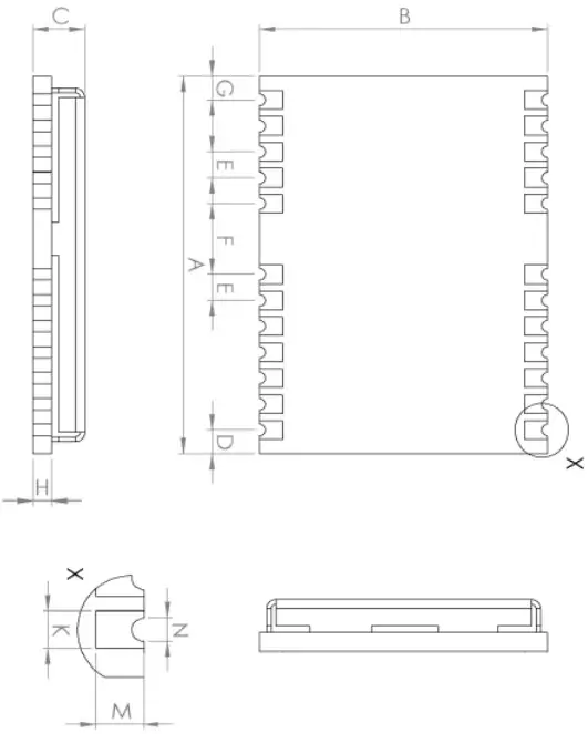
Figure 3-1 Mechanical Layout
Pin Definition
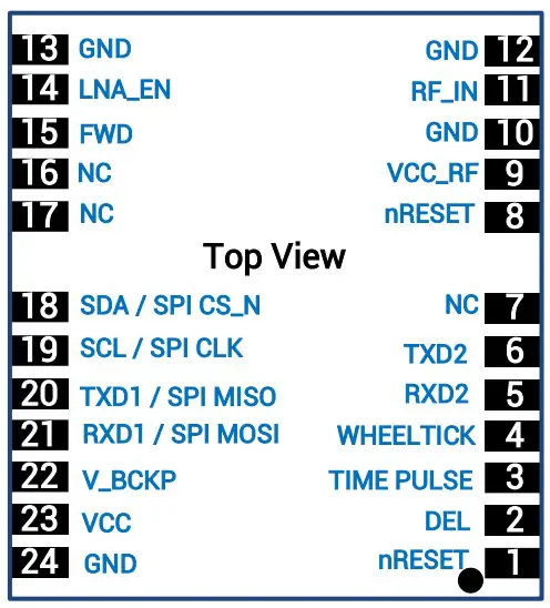
Figure 3-2 Pin Assignment
| PinNo | Name | I/O | ElectricalLevel | Description |
| 1 | nRESET | I | LVTTL | Reset pin, active low.Keep it floating if not in use. |
| 2 | DEL | I | — | Interface selection pin.If DEL is set low level, SPI is available. If DEL is set high or floating, UART and I2C become available. |
| 3 | TIMEPULSE | O | LVTTL | Pulse per second (1PPS) |
| 4 | WHEELTICK | I | LVTTL | Odometer speed pulse input. Keep it floating if not in use.It is strongly recommended to use this pin. The maximum pulse frequency is 5K Hz, and the minimum pulse width is greater than 100 us.Note: Incorrect signals of the odometer will lead to serious problems in the use of the product. Please make sure the signalis correct. |
| 5 | RXD2 | I | LVTTL | UART 2 receiving data |
| 6 | TXD2 | O | LVTTL | UART 2 transmitting data |
| 7 | NC | — | — | Floating |
| 8 | nRESET | I | LVTTL | Reset pin, active low.Keep it floating if not in use. |
| 9 | VCC_RF | O | Antenna feed output.It is recommended to use an external power supply rather than the VCC_RF pin to feed the antenna. | |
| 10 | GND | — | — | Ground |
| 11 | RF_IN | I | — | GNSS signal input |
| 12 | GND | — | — | Ground |
| 13 | GND | — | — | Ground |
| 14 | LNA_EN | O | — | Enable external LNA |
| 15 | FWD | I | LVTTL | Odometer direction input. Keep it floating if not in use.It is strongly recommended to use it. High level = forwardLow level = reverseNote: Incorrect signals of the odometer will lead to serious problems in the use of the product. Please make sure the signal is correct. |
| 16 | NC | — | — | Floating |
| 17 | NC | — | — | Floating |
| 18 | SDA / SPI CS_N | — | — | I2C data (D_SEL=VCC or floating)/SPIchip select (D_SEL=GND) |
| 19 | SCL / SPI CLK | — | — | I2C clock (D_SEL=VCC or floating)/SPIclock (D_SEL=GND) |
| 20 | TXD1/ SPI MISO | O | LVTTL | SPI Master In Slave Out (D_SEL=GND); UART TXD signal (D_SEL=VCC orfloating) |
| 21 | RXD1/ SPI MOSI | I | LVTTL | SPI Master Out Slave In (D_SEL=GND); UART RXD signal (D_SEL=VCC orfloating) |
| 22 | V_BCKP | I | 1.7 V~3.6 V | Backup voltage supply, applicable for hot start. If you do not use hot start, connect V_BCKP to VCC. Do NOT leave it floatingor connect it to ground. |
| 23 | VCC | — | 2.7 V~3.6 V | Supply voltage |
| 24 | GND | — | — | Ground |
PCB Packaging
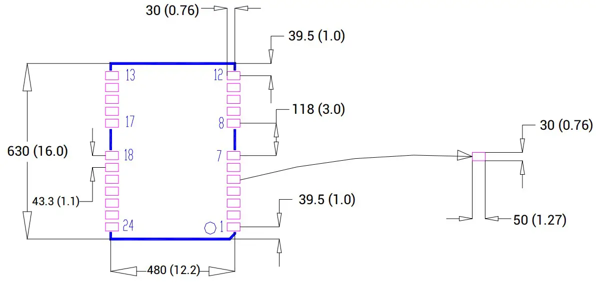
Figure 3-3 UM621N Recommended PCB Packaging (unit: mil, in brackets:
mm)
Package
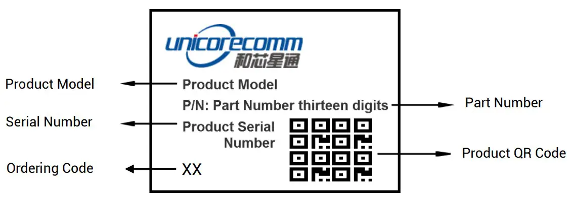
Label Description
Ordering Information
| ProductModel | OrderingCode | PN | Description |
| UM621N | 02 | 2310414000008 | Automotive grade dual-frequency GNSS+MEMS module, supporting firmware upgrade, 16.0 mm x 12.2 mm, 500 pieces/reel |
Package Description
The UM621N modules use carrier tape and reel (suitable for mainstream surface mount devices), packaged in vacuum-sealed aluminum foil antistatic bags, with desiccant inside to prevent moisture. When using reflow soldering process to solder the modules, please strictly comply with IPC standard to conduct temperature and humidity control. As packaging materials such as the carrier tape can only withstand the temperature of 55 degrees Celsius, modules shall be removed from the package during baking.
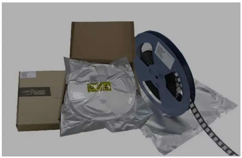
Figure 4-1 UM621N Module Package
| Item | Description |
| Number of Modules | 500 pieces/reel |
| Reel Size | Tray: 13″External diameter: 330 mm Internal diameter: 100 mm Width: 24 mmThickness: 2.0 mm |
| Carrier Tape | Space between (center-to-center distance): 20 mm |
UM621N modules are rated at MSL level 3. Please refer to the relevant IPC/JEDEC
standards for baking requirements. Users may access to the website www.jedec.org to
get more information.
The shelf life of UM621N modules packaged in vacuum-sealed aluminum foil antistatic bags is one year.
Clean
DO NOT use alcohol or other organic solvents to clean, which may lead to soldering flux residues flooding into the shielding shell, causing mildew and other problems.
Reflow Soldering
In order to avoid the device falling off, the module should be placed on the top of the main board during soldering. Reflow soldering temperature curve is recommended as shown in figure 6-1 below (M705-GRN360 is recommended for solder paste).
Note: The module can only be soldered once.
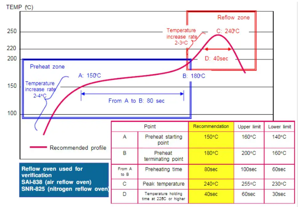
Figure 6-1 Reflow Soldering Temperature Curve
Note: The apertures in the stencil need to meet the customer’s own design requirements and inspection specifications, and the thickness of the stencil should be above 0.15 mm. It is recommended to be 0.18 mm.
 Unicore Communications, Inc.
F3, No.7, Fengxian East Road, Haidian, Beijing, P.R.China, 100094
www.unicorecomm.com
Phone: 86-10-69939800
Fax: 86-10-69939888
[email protected]


