unicore-comm UM4B0 High Precision GNSS Module

Product Information
UNICORECOMM UM4B0 GPS/BDS/GLONASS/Galileo or All-constellation All-frequency Uni c RTK Positioning Module
The UNICORECOMM UM4B0 is a GPS/BDS/GLONASS/Galileo or All-constellation All-frequency Uni c RTK Positioning Module. It has 432 channels and is based on NebulasII SoC. It supports GPS L1/L2/L5, BDS B1I/B2I/B3I/B1C/B2a, GLONASS L1/L2, Galileo E1/E5a/E5b, and QZSS L1/L2/L5 frequencies. The module has a horizontal accuracy of 1.5m for single point positioning and 0.4m for RTK positioning. It has a vertical accuracy of 2.5m for single point positioning and 0.8m for RTK positioning. The module also has a heading accuracy (RMS) of 1cm+1ppm and a velocity accuracy (RMS) of 1.5cm+1ppm. The module’s initialization reliability is 99.9% with an RTK initialization time of 5ms.
Installation and Operation
The installation and operation instructions for the UNICORECOMM UM4B0 module are provided in the user manual. The manual provides detailed information on the hardware, hardware design, installation and configuration, configuration commands, antenna detection, firmware upgrade, production requirement, and packaging.
Hardware
The hardware section of the manual provides information on the physical specifications of the module such as weight and dimensions. It also provides information on the antenna input pin ANT_IN and the external antenna feed design. The module provides a +3.3V antenna feed, and when an active antenna of +3.3~5V is adopted, make sure the 50 antenna impedance is matched.
Hardware Design
The hardware design section of the manual provides information on the UM4B0 module’s features, installation, specification, and use. The manual is a generic version, and readers should refer to the appropriate part of the manual according to their purchased product configuration concerning CORS, RTK, and Heading. The manual is intended for technicists who know GNSS Receiver to some extent but not for general readers.
Installation and Configuration
The installation and configuration section of the manual provides detailed information on the operation procedures for the module.
Configuration Commands
The configuration commands section of the manual provides information on the commands that can be used to configure the module.
Antenna Detection
The antenna detection section of the manual provides information on how to detect an antenna connected to the module.
Firmware Upgrade
The firmware upgrade section of the manual provides information on how to upgrade the module’s firmware.
Production Requirement
The production requirement section of the manual provides information on the requirements for producing the module.
Packaging
The packaging section of the manual provides information on how the module is packaged.
Revision History
| Version | Revision History | Date |
| Ver. 1.0 | First Edition | Feb. 2017 |
| R3.1 | Add the related description to clarify the VCC restrictions | 2019-08-22 |
| R3.2 | Chapter 2.2: add the working current info of No.17 pin | 2019-09-18 |
| R3.3 | 2.5 Physical Specifications: update the weight value from 8.8 to 9.2 1.1 Overview: update the product diagram | 2020-02-26 |
| R3.4 | Add QZSS | 2020-07-01 |
| R3.5 | Fix typo/update BDS frequencies | 2020-10-21 |
| R3.6 | Update dimensions | 2020-10-28 |
| R3.7 | Add external antenna feed reference circuit | 2020-12-17 |
| R3.8 | Update COFIG command | 2021-01-22 |
| R4 | Remove information on the MEMS device and add RF input power consumption of antennas | 2021-04-13 |
| R4.1 | Add average current in chapter 2.4 | 2021-06-23 |
| R4.2 | Modify pin19 in Figure 2-2 | 2021-07-01 |
Disclaimer
- Information in this document is subject to change without notice and does not represent a commitment on the part of Unicore Communications, Inc. No part of this manual may be reproduced or transmitted in any form or by any means, electronic or mechanical, including photocopying and recording, for any purpose without the express written permission of a duly authorized representative of Unicore Communications, Inc. The information contained within this manual is believed to be true and correct at the time of publication.
- © Copyright 2009-2021 Unicore Communications, Inc. All rights RSV.
Foreword
- This <User Manual> offers you information in the features of the hardware, the installation, specification and use of UNICORECOMM UM4B0 product.
- This manual is a generic version. Please refer to the appropriate part of the manual according to your purchased product configuration, concerning CORS, RTK and Heading.
Readers it applies to
- This <User Manual> is applied to the technicists who know GNSS Receiver to some extent but not to the general readers.
Introduction
Overview
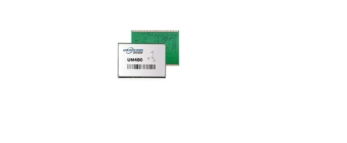
- UM4B0 is a high precision positioning and heading RTK module developed by Unicore Communications, targeting light robots, UAVs, intelligent vehicles, GIS information collection, etc.
- By employing a single UC4C0 (432 channel tracking) baseband chip and a single RF chip, using single-sided SMD packaging, UM4B0 has achieved the smallest size
(30x40mm) in this industry with high accuracy heading and positioning output. It can simultaneously track BDS B1I/B2I/B3I/B1C/B2a + GPS L1/L2/L5 + GLONASS
L1/L2+Galileo E1/E5a/E5b.
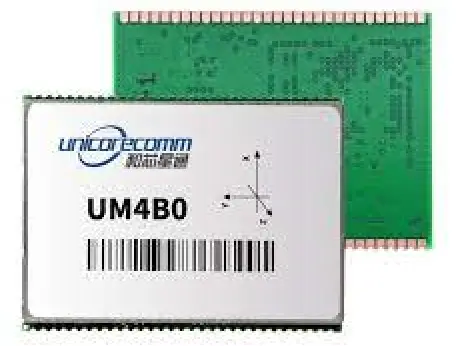
Figure 1-1 UM4B0 Module
Key Features
- 30*40mm, the smallest multi-system multi-frequency high precision module
- Support GPS L1/L2/L5+GLONASS L1/L2+BDS B1I/B2I/B3I/B1C/B2a+Galileo E1/E5a/E5b
- Based on 432 channel NebulasII GNSS SoC
- 20Hz update rate
- Instant RTK initialization and long-distance RTK
- Enhanced multi-system multi-frequency RTK technology, JamShield Adaptive narrow-band anti-interference and U-AutoAlign multi-path mitigation
- Support odometer input and external high-performance IMU interface*
- SMD packaging
Technical Specifications
Table 1-1 Performance Specifications
| Channels | 432 channels, based on NebulasII SoC | RTK Initialization Time | <5s (typical) |
| Frequency | GPS L1/L2/L5 BDS B1I/B2I/B3I/B1C/B2a GLONASS L1/L2 Galileo E1/E5a/E5b QZSS L1/L2/L5 | Initialization Reliability | >99.9% |
| Single Point Positioning | Horizontal: 1.5m | Cold Start | <25s |
| Vertical: 2.5m | Reacquisition | <1s | |
| DGPS(RMS) | Horizontal: 0.4m | Correction | RTCM 3.0/3.2/3.3 |
| Vertical: 0.8m | |||
| RTK(RMS) | Horizontal: 1cm+1ppm | Data Output | NMEA-0183, Unicore Binary |
| Vertical: 1.5cm+1ppm | Update Rate | 20Hz | |
| Heading Accuracy (RMS) | 0.2 degree@1 m baseline | Time Accuracy (RMS) | 20ns |
| Velocity Accuracy (RMS) | 0.03m/s | Power Consumption | 1.8W |
| Dimension | 30×40×4 mm |
Table 1-2 Functional Ports
| 3x UART, 1xI2C, 1x SPI (LV-TTL) | 1x1PPS(LV-TTL) |
| 1x Event input |
Interfaces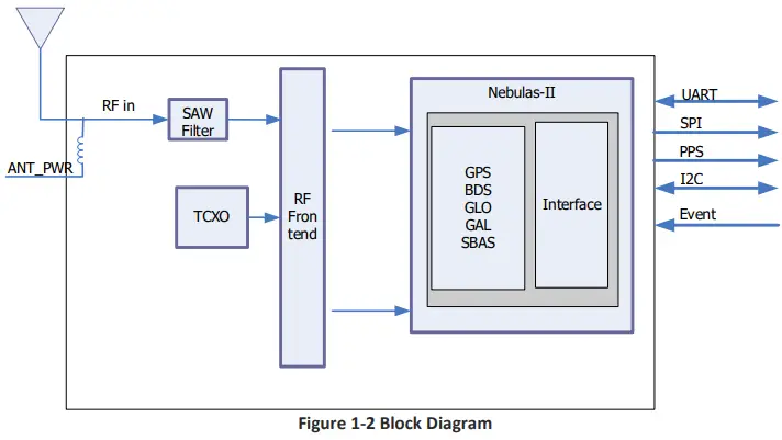
- RF Part
- The receiver gets filtered and enhanced GNSS signal from the antenna via a coaxial cable. The RF part converts the RF input signals into the IF signal, and converts IF analog signal into digital signals required for NebulasII (UC4C0) digital processing.
- NebulasII SoC (UC4C0)
- The UM4B0 incorporates the processing from the NebulasII (UC4C0), UNICORECOMM’s new generation high precision GNSS SoC with 55nm low power design, which supports up to 12 digital intermediate frequency or 8 analog intermediate frequency signals and can track 12 navigation signals with 432 channels.
- 1PPS
- UM4B0 outputs 1 PPS with adjustable pulse width and polarity.
- Event
- UM4B0 provides 1 Event Mark Input with adjustable pulse width and polarity.
Hardware
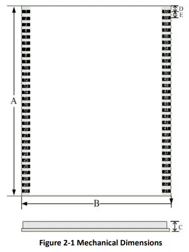
Dimensions
Table 2-1 Dimension
| Symbol | Min. (mm) | Typ. (mm) | Max. (mm) |
| A | 38.00 | 40.00 | 40.50 |
| B | 29.80 | 30.00 | 30.2 |
| C | 3.80 | — | 4.00 |
| D | 1.57 | 1.58 | 1.59 |
| E | 1.26 | 1.27 | 1.28 |
| Pin | 1.07 |
Pin Definition (Top View)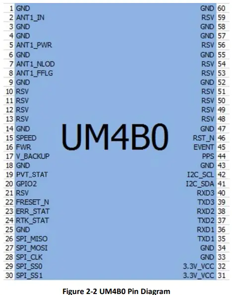
Table 2-2 Pin Definition
| No | Pin | I/O | Description |
| 1 | GND | – | Ground |
| 2 | ANT_IN | I | GNSS antenna signal input |
| 3 | GND | – | Ground |
| 4 | GND | – | Ground |
| 5 | ANT_PWR | I | GNSS antenna power supply |
| 6 | GND | – | Ground |
| 7 | ANT_NLOD | O | GNSS antenna open circuit indicator 1: normal 0: antenna is open circuit |
| 8 | ANT_FFLG | O | GNSS antenna short circuit indicator 1: normal 0: antenna is short circuit |
| 9 | GND | Power | DGND/GND |
| 10 | RSV | – | RSV |
| 11 | RSV | – | RSV |
| 12 | RSV | – | RSV |
| 13 | RSV | – | RSV |
| 14 | GND | – | Ground |
| 15 | SPEED | I | Odometer- pulse |
| 16 | FWR | I | Odometer- direction |
|
17 |
V_BACKUP |
I | When the main power supply of the module VCC is cut off, V_BCKP supplies power to RTC and SRAM. Level requirements: 2.0~ 3.6 V, and the working current is about 10uA. Can be suspended without using the hot start function. |
| 18 | GND | – | Ground |
| 19 | PVT STAT | O | PVT positioning indicator, active-high. The module outputs high level when positioning is available and outputs low level when no positioning is proceeded. |
| 20 | GPIO2 | I/O | Common IO |
| 21 | RSV | – | RSV |
| 22 | FRESET_N | I | Reset to factory default (clear all user settings), LVTTL active-low, activate for longer than 5 seconds. |
| 23 | ERR_STAT | O | Abnormal indicator, active-high. When the RTK solution is fixed, it outputs high level, otherwise outputs low level when the module completes its self-diagnosis. |
|
24 |
RTK_STAT |
O | RTK positioning indicator, active-high. When the module’s self-diagnosis system fails, it outputs high level; otherwise outputs low level when it’s in other positioning states or no positioning is proceeded. |
| 25 | GND | – | Ground |
| 26 | SPI_MISO | I | SPI data input |
| No | Pin | I/O | Description |
| 27 | SPI_MOSI | O | SPI data output |
| 28 | SPI_CLK | O | SPI clock |
| 29 | SPI_SS0 | O | SPI chip select 0 |
| 30 | SPI_SS1 | O | SPI chip select 1 |
| 31 | 3.3V_VCC | Power | Power Supply (+3.3V) |
| 32 | 3.3V_VCC | Power | Power Supply (+3.3V) |
| 33 | GND | – | Ground |
| 34 | GND | – | Ground |
| 35 | TXD1 | O | COM 1 transmit |
| 36 | RXD1 | I | COM 1 receive |
| 37 | TXD2 | O | COM 2 transmit |
| 38 | RXD2 | I | COM 2 receive |
| 39 | TXD3 | O | COM 3 transmit |
| 40 | RXD3 | I | COM 3 receive |
| 41 | I2C_SDA | I/O | I2C data |
| 42 | I2C_SCL | I/O | I2C clock |
| 43 | GND | – | Ground |
| 44 | PPS | O | Pulse per second |
| 45 | EVENT | I | Event Mark |
| 46 | RST_N | I | Fast reset, will not clear user configurations. Active Low, > 5 ms |
| 47 | GND | – | Ground |
| 48 | RSV | – | RSV |
| 49 | RSV | – | RSV |
| 50 | RSV | – | RSV |
| 51 | RSV | – | RSV |
| 52 | GND | – | Ground |
| 53 | RSV | – | RSV |
| 54 | RSV | – | RSV |
| 55 | GND | – | Ground |
| 56 | RSV | – | RSV |
| 57 | GND | – | Ground |
| 58 | GND | – | Ground |
| 59 | RSV | – | RSV |
| 60 | GND | – | Ground |
Electrical Specifications
Table 2-3 Absolute Maximum Ratings
| Item | Pin | Min | Max | Unit |
| Power Supply (VCC) | Vcc | -0.3 | 3.6 | V |
| Voltage Input | Vin | -0.3 | VCC+0.2 | V |
| LNA Input | ANT_PWR | -0.3 | 6 | V |
| GNSS Antenna Signal Input | ANT_IN | -0.3 | ANT_PWR | V |
| RF Input Power Consumption of Antenna | ANT_IN input power | +15 | dBm | |
| VCC Ripple (Rated Max.) | Vrpp | 0 | 50 | mV |
| Item | Pin | Min | Max | Unit |
| Voltage Input (pins other than RXD1, RXD2, RXD3) | Vin | -0.3 | 3.6 | V |
| Maximum ESD stress | VESD(HBM) | ±2000 | V |
Operational Conditions
Table 2-4 Operational Conditions
| Item | Pin | Min | Typical | Max | Unit | Condition |
| Power Supply (VCC) | Vcc | 3.2 | 3.3 | 3.6 | V | |
| Pulse current* | Iccp | 8.8 | A | Vcc = 3.3 V | ||
| LOW-Level Input Voltage | Vin_low_1 | -0.3 | VCC*0.3 | V | ||
| High-Level Input Voltage | Vin_high_1 | VCC*0.7 | VCC+0.3 | V | ||
| LOW Level Output Voltage | Vout_low | 0 | 0.45 | V | Iout= 4 mA | |
| High Level Output Voltage | Vout_high | VCC-0.45 | VCC | V | Iout =4 mA | |
| Antenna Gain | Gant | 20 | 30 | 36 | dB | |
| Noise Figure | Nftot | 2.5 | 3 | 3.5 | dB | |
| LNA Input | ANT_PWR | 3.3 | 5 | 5.5 | V | < 100mA |
| Operating Temperature | Topr | -40 | 85 | °C | ||
| Power Consumption | P | 1.5 | 1.8 | 2.0 | W | |
| Average Current | Iavg | 0.545 | A |
NOTE: Since the product contains capacitors at the input, inrush current will occur during power-on. Evaluate in the actual environment in order to check the effect of the supply voltage drop due to the inrush current.
Physical Specifications
Table 2-5 Physical Specifications
| Size | 30×40×4 mm |
| Weight | 9.2g |
| Temperature | Operating: -40℃~+85℃ |
| Storage: -55℃~+95℃ | |
| Humidity | 95% No condensation |
| Vibration | GJB150.16-2009, MIL-STD-810 |
| Shock | GJB150.18-2009, MIL-STD-810 |
Hardware Design
Design in Considerations
- To make UM4B0 work properly, you need to properly connect the following
- The module’s VCC should be monotonic when powered on, the initial level should be lower than 0.4V, and the undershoot and ringing should be guaranteed to be within 5% VCC
- Provide stable power to the VCC pin
- Connect all the GND pins to ground
- Connect ANT_IN signal to the antenna, and ensure the 50-ohm impedance matching
- Connect ANT_PWR to +3.3~5.5 V voltage, then supply +3.3~5.5 V feed to the antenna through ANT_IN
- Ensure COM1 is connected to a PC or an external processor, and users can use this serial port to receive position data. COM1 is also necessary for firmware upgrades
- Properly connect the module’s reset pin FRESET_N to ensure complete reset of the module. It will restore the module to the manufacturing configuration.
- When ANT_NLOD, ANT_FFLG and antenna detection indication signal are connected, the IO without any pull-up/down of the client MCU terminal is required at the input.
- In order to obtain proper performance, special concerns should be paid during the design:
- Power supply: A table and low ripple power supply is necessary for good performance. Make sure the peak-to-peak voltage ripple does not exceed 50mVpp. It is recommended to use a power chip with current output capacity greater than 2A to power the board.
- Use LDO to ensure the purity of power supply
- Try to place LDO close to the module in layout
- Widen the tracks of power circuit or use copper pour surface to transmit current
- Avoid walking through any high-power or high inductance devices such as a magnetic coil
- Interfaces: Ensure that the signals and baud rate of the main equipment match those of the UM4B0 module
- Antenna interface: Make sure the antenna impedance matches, and the cable is short without any kinks, try to avoid all acute angles
- Try to avoid designing in any circuits underneath UM4B0
- This module is a temperature sensitive device, so dramatic changes in temperature will result in reduced performance. Keep it away as far as possible from any high-power high-temperature air and heating devices
UM4B0 Reference Design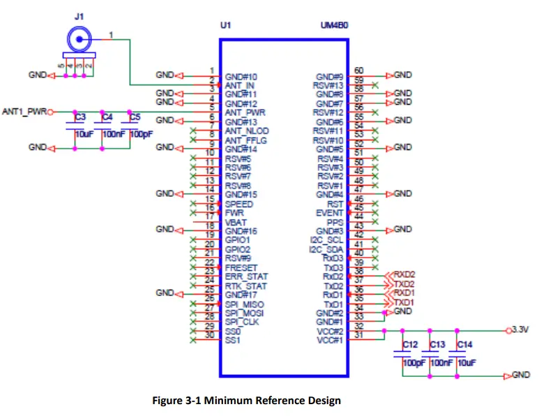
Pins
Table 3-1 Pin Notes
| Pin Name | Pin | I/O | Description | Notes | |
| Power Supply | VCC | 31, 32 | Power | Voltage Supply | Stable, clean low ripple power supply, peak ripple power lower than 50mVpp is preferred |
| ANT_PWR | 5 | Power | Antenna Power Supply | Voltage supply for active antenna | |
| GND | 1, 3, 4, 6, 9, 14, 18, 25, 33, 34, 43, 47, 52, 55, 57, 58, 60 | Power | Ground | Connect all the GND signals to ground. Better to use copper pour surface. | |
| Antenna | ANT_IN | 2 | I | Satellite Signal Input | 50 Ω impedance matching |
| UART | TXD1 | 35 | O | COM1 Transmit Data | COM1 output, leave unconnected if not used |
| Pin Name | Pin | I/O | Description | Notes | |
| RXD1 | 36 | I | COM1 Receive Data | COM1 input, leave unconnected if not used | |
| TXD2 | 37 | O | COM2 Transmit Data | COM2 output, leave unconnected if not used | |
| RXD2 | 38 | I | COM2 Receive Data | COM2 input, leave unconnected if not used | |
| TXD3 | 39 | O | COM3 Transmit Data | COM3 output, leave unconnected if not used | |
| RXD3 | 40 | I | COM3 Receive Data | COM3 input, leave unconnected if not used | |
| System | FRESET_N | 22 | I | Hardware Reset (low effective) | Restore factory settings by lowering FRESET_N for no less than 5 seconds |
| PPS | 44 | O | PPS signal | PPS | |
| EVENT | 45 | I | EVENT signal | Event |
PCB Packaging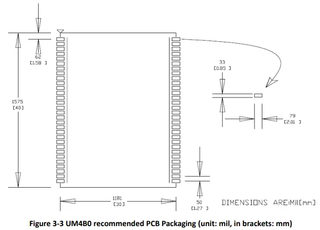
Reset Signal
The UM4B0 module can’t work properly unless it is correctly reset after powering on. To ensure an effective reset, the reset pin (RST) and power supply pin (VCC) must meet the following time sequence requirement. To reset UM4B0 during normal operation, please pull the RST pin to a low level for more than 5ms.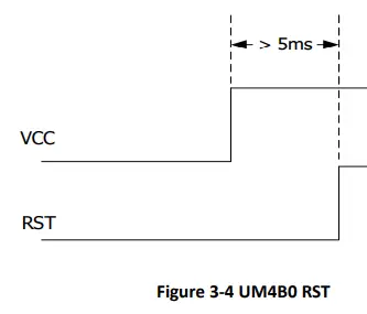
Antenna
The module has the antenna input pin ANT_IN. It provides a +3.3V antenna feed, when an active antenna of +3.3~5V is adopted, please make sure the 50 Ω antenna impedance is matched.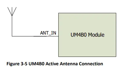
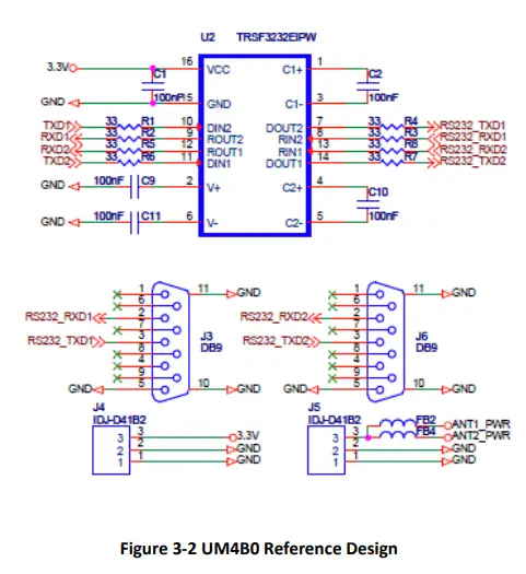
External Antenna Feed Design
- UM4B0 feeds the antenna signals to the required circuits internally, but in order to effectively prevent damage from lightning and surges, circuit protection should be installed externally to protect the module.
- High voltage and high-power protection chips should be used to feed the antenna from the outside of the module. Gas discharge tube, varistor, TVS tube and other high-power protective devices may be used in the antenna circuit to effectively improve the prevention against lightning stroke and surge.

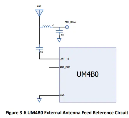
Remarks:
- a) L1, feed inductor, 68nH RF inductor in 0603 package is recommended;
- b) C1, decoupling capacitor, it is recommended to connect two capacitors of 100nF/100pF in parallel;
- C2, DC blocking capacitor, recommended 100pF capacitor.
Installation and Configuration
ESD Handling Precautions
UM4B0 Module is an Electrostatic Sensitive Device (ESD) and special precautions when handling are required.
- Electrostatic discharge may cause damages to the device. All operations mentioned in this chapter should be carried out on an antistatic workbench, wearing an antistatic wrist strap and using a conductive foam pad. If an antistatic workbench is not available, wear an antistatic wrist strap and connect the other end to a metal frame to avoid the effects of static electricity.
- Hold the edge of the module, not in direct contact with the components
- Please check carefully whether the module has obviously loose or damaged components.

- Please check the contents of the package carefully after receiving the package of UM4B0.
- UM4B0 EVK suite (or evaluation board)
- User manual
- UPrecise software
- Qualified antenna
- MMCX antenna cable
- PC or Laptop with serial ports (Win7 or above), with UPrecise installed
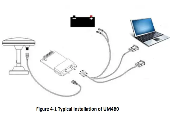
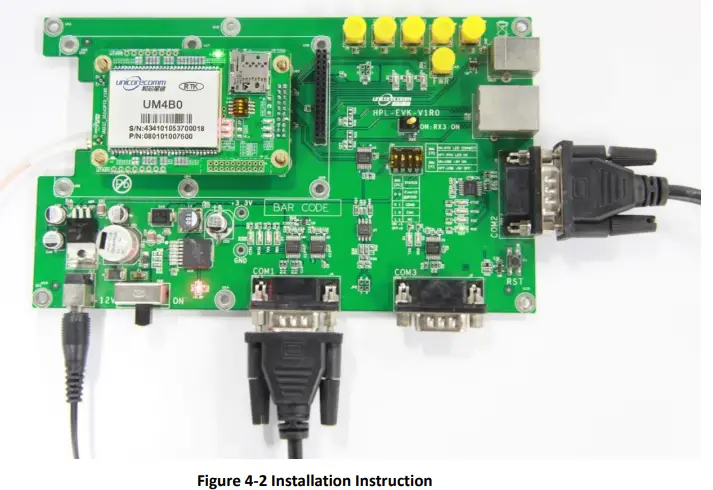
Hardware Installation
- After the above preparation, please follow the steps below to install:
- Step 1: Make sure to take all the anti-static measures, such as wearing an anti-static wrist strap, grounding the workbench;
- Step 2: Align UM4B0 transfer board positioning holes and pins with EVK, and fix it in the EVK. EVK provides power supply and standard communication interface for the module to communicate with peripheral devices;
- NOTE: The RF connector on the board is MMCX, and the suitable connecting wire should be selected according to the package. The input signal gain at the antenna interface is optimal between 20 and 36 dB. Please select the appropriate antenna, antenna cable and online LNA accordingly.

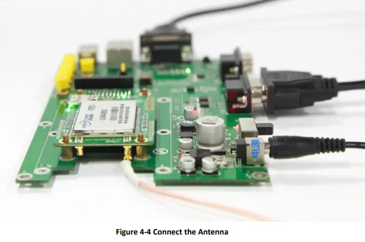
- Step 3: Select the GNSS antenna with appropriate gain, and fix it in a stable, non-block area, using the coaxial radio frequency cable to connect the antenna to UM4B0 EVK;
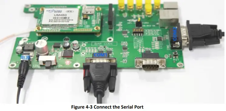
- Step 4: Connect the PC to the EVK serial port through direct serial cable;

- Step 5: Connect a 12V adapter to the EVK power input, and switch on to power the device;

- Step 6: Open the UPrecise software on the PC;
- Step 7: Control the receiver through UPrecise to send commands or to log data.
Start-Up
The power supply for UM4B0 is 3.3VDC. Before powering on the device, please connect UM4B0 serial port to the GNSS antenna. The receiver is started and the communication is connected after powering up. Testing tools are provided for module testing.
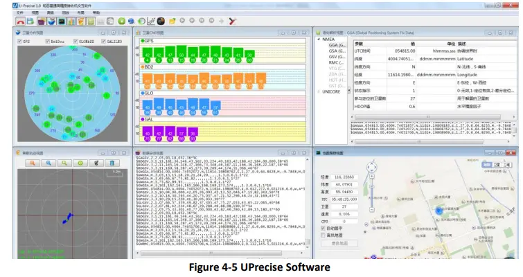
Configuration and Output
UNICORECOMM UPrecise software provides a user-friendly graphical interface to control and display the operation of your receiver. The features of Uprecise include:
- Logging Control View: Graphic interface for data logging
- Console window for sending command to the receiver (Console View)
- Displaying the receiver’s output in ASCII-format (ASCII View)
- Graphic window for displaying Position of satellite, PRN, and Signal/Noise Ratio (Constellation View)
- Historical and present Trajectory of the receiver (Trajectory View)
- Position/Velocity/Time of the receiver (PVT View)
- Apart from the basic functions above, UPrecise offers advanced functions as follows:
- Selecting and recording the log
- Sending commands to the receiver
- Operating and configuration of the ASCII view
- The trajectory view for displaying the present point and the past point of the receiver
- Switching Views over the tracking window
- Switching between Constellation Views
- Resetting the receiver
- Replaying the GGA log

Operation Procedures
- Step 1. Follow 4.2 Installation Guide to connect the power source, antenna to the board, and turn on the EVK switch
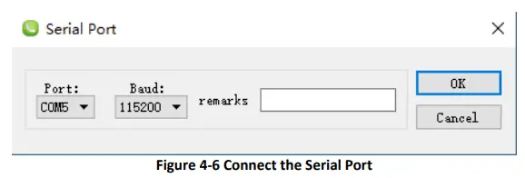
- Step 2. Click file – > connect the serial port, and set the baud rate; the default baud rate of UB4B0M is 115200bps

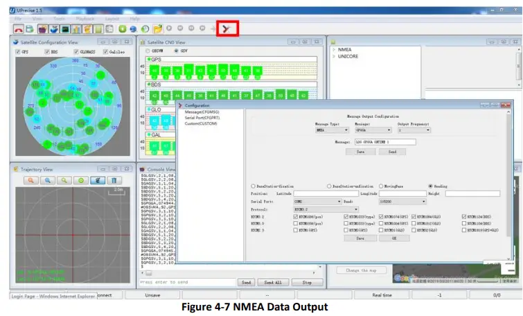
- Step 3. Click the receiver settings button to configure the NMEA message output. It is recommended to configure GPGGA, GPGSV, and other messages.

- Step 4. Click the receiver settings button to configure the NMEA message output, then click send. It is recommended to configure GPGGA, GPGSV, and other messages.
- Step 5. In the data session window, click “Send all Message” to complete all the NMEA message output (update rate 1Hz). Right click in the data session window to adjust: output log font size, stop / resume log output, or clear log content, etc.
- Step 6. Use various views of UPrecise to configure or input commands as required.
Configuration Commands
- UM4B0 supports abbreviated ASCII format. Simplified ASCII format without check bit is more accessible to user commands. All commands are composed of a log heading and configuration parameters (If parameters are null, there will be only one heading in the command). Header field contains the command name or message headers. UM4B0 is simple to use, and common instructions are shown in the following table:
| Command Name | Description |
| freset | Restore the factory default settings. Note: the factory set baud rate is 115200 bps. |
| version | Query version information for all components. |
| config | Query status of the serial port |
| mask GPS | Mask (disable) tacking of GPS system satellites, BDS/GPS/GLO/GAL systems are all supported to disable |
| unmask BDS | Unmask (enable) BDS system satellites, BDS/GPS/GLO/GAL systems are all supported to enable |
| config com1 115200 | Configure com1 port operating at 115200 baud rate. The usable COM ports are COM1, COM2, COM3. The baud rate could be 9600, 19200, 38400, 57600, 115200, 230400, 460800 bps |
| unlog | Disable all outputs of the port in use |
| saveconfig | Save the settings |
| Base/Rover Station Settings | |
| mode base time 60 1.5 2.5 | Within 60 seconds of the automatic positioning of the receiver, or when the standard deviation of horizontal positioning is no more than 1.5 m and that of vertical positioning is no more than 2.5 m, set the average value of horizontal and vertical positioning results as the fixed base station coordinates. The base station coordinates are automatically set in this mode. Restarting the receiver triggers a new calculation and repositioning. |
| mode base lat lon height | Set datum coordinates manually: latitude, longitude, height. Datum coordinates are fixed, when restarting the receiver. For example, lat=40.07898324818, lon=116.23660197714, height=60.4265 Note: Longitude and latitude can be obtained by GGA command. The Southern Hemisphere corresponds to a negative latitude value; The Western Hemisphere corresponds to a negative longitude value |
| mode base | Set the default base station mode |
| Command Name | Description |
| mode movingbase | Set the moving base station mode |
| mode rover | Set the default rover station mode (This command transfers the receiver from base station mode to rover mode.) |
| rtcm1033 comx 10 rtcm1006 comx 10 rtcm1074 comx 1 rtcm1124 comx 1 rtcm1084 comx 1 rtcm1094 comx 1 | Set base station to transmit RTCM messages to rover receivers via CMOX, ICMOX, and NCMOX. The serial port CMOX can be assigned as COM1, COM2, COM3. |
| NMEA0183 Messages Associated | |
|
gpgga comx 1 | Set GGA message output rate at 1Hz. Users can choose the message type and update rate. 1, 0.5, 0.2, 0.1 corresponds to the frequency 1Hz, 2Hz, 5Hz, 10Hz respectively. The optional message types are: GGA, RMC, VTG, ZDA, NTR |
| gphdt comx 1 | Output the heading message HDT of the present instant. Vessel Heading message types include HDT and TRA |
RTK Reference Station Configuration
- If the precise coordinates are known, the precise coordinates could be set as in this example
- Mode base 40.07898324818 116.23660197714 60.4265 // set lat lon height rtcm1033 com2 10 // RTCM1033 input from com2 rtcm1006 com2 10
- rtcm1006 com2 10
- rtcm1074 com2 1
- rtcm1084 com2 1
- rtcm1094 com2 1
- rtcm1124 com2 1
- save config
If precise coordinates are unknown:
- Mode base time 60 1.5 2.0 // 60 seconds position average
- rtcm1033 com2 10
- rtcm1006 com2 10
- rtcm1074 com2 1
- rtcm1084 com2 1
- rtcm1094 com2 1
- rtcm1124 com2 1
- saveconfig
RTK Rover Configuration
- RTK Rover stations (rover station) receive differential correction data sent from reference stations and receive satellite signals to provide an RTK positioning solution and realize RTK high-precision positioning with cm or mm-level accuracy. Common instructions for configuring RTK rover are as follows:
- gngga 1
- saveconfig
Moving Base Configuration
- RTK reference station provides precisely known coordinates of a fixed station. Unlike the RTK reference station, moving base station is in motion, at the same time receives the satellite information, and sends it to the rover station receiver (to be determined) directly or after processing. The rover station receiver receives satellite observations as well as information from the moving base station, to make relative positioning and determine the position of the rover station. Commonly used instructions to set the moving base station are as follows:
- Mode movingbase
- rtcm1006 com2 1
- rtcm1074 com2 1
- rtcm1084 com2 1
- rtcm1094 com2 1
- rtcm1124 com2 1
- saveconfig
Heading Configuration
- GNSS heading refers to the clockwise angle between true North and the baseline vector constituted by the two GNSS antennas. Commonly used instructions are as follows:
- Mode heading
- gphdt com1 1
- saveconfig
Antenna Detection1
- The UM4B0 module offers antenna open/short detection. The corresponding pins are ANT_NLOAD and ANT_FFLG
| Ant_Nlod | Ant_Fflg | Status | Status Description |
| 1 | 1 | On | Normal |
| 0 | 1 | Off | Open |
| 1 | 0 | Short | Short |
| 0 | 0 | RSV | RSV |
- The current monitoring chip outputs 2 bit high and low voltage; the software portion sets 2 bit IO of corresponding NII as input pull-up, and then queries the status of 2 bit IO to check the antenna state.
- If ANT_PWR malfunctions, the query result is invalid.
- If the antenna is not fed by ANT_PWR but by other means, the query result is invalid.
Firmware Upgrade
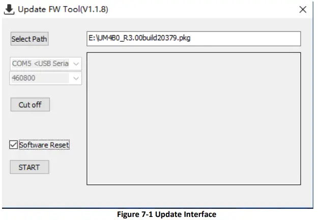
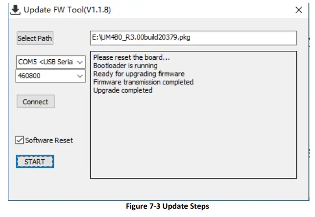
- Uprecise software is used for the remote update of UM4B0. Please follow the steps below to upgrade the device:

- Click “…” to browse the firmware update package, and click “Start” to start the firmware upgrading process (uncheck software reset):

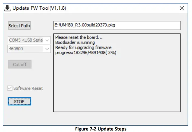
- Waiting for the process to complete 100% (the upgrade time is normally within 5min):

Production Requirement
- Recommended thermal cycle curve is as follows:

- Temperature rising stage
- Rising slope: Max. 3℃/s
- Rising temperature range:50℃-150℃
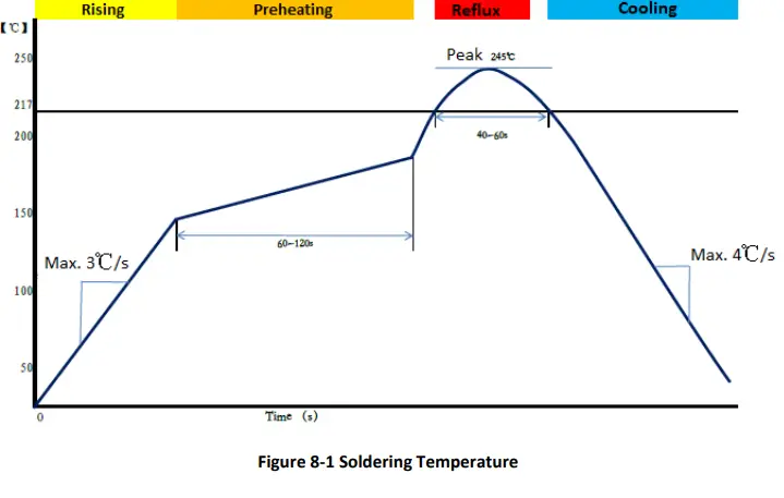
Preheating stage
- Preheating time: 60 – 120 s
- Preheating temperature range: 150 – 180℃
Reflux Stage
- Over melting temperature (217℃) time: 40 – 60 s
- Peak temperature: no higher than 245℃
Cooling Stage
- Cooling slope: Max. 4℃ / s
Notes:
- In order to prevent fall off during soldering of modules, please avoid soldering the module in the back of the Board during design, that is, better not go through soldering cycle twice.
- The setting of temperature depends on many factors, such as type of Board, solder paste type, solder paste thickness, etc. Please also refer to the relevant IPC standards and indicators for solder paste.
- Since the lead-free soldering temperatures are relatively low, if using this soldering method, please give priority to other components on the Board.
Packaging
- UM4B0 modules are delivered in trays, which is suitable for mainstream SMT equipment. Each box contains 5 trays, so there are 150 UM4B0 modules in the box.
Table 9-1 Package Information
| No | Description |
| 1 | 10 trays/box |
| 2 | 10 antistatic packaging boxes/tray |
| 3 | 1 UM4B0/antistatic packaging box |
- Hexinxing Technology (Beijing) Co., Ltd.
- Unicore Communications, Inc.
- 3rd Floor, Beidouxingtong Building, No. 7 Fengxian East Road, Haidian District, Beijing
- F3, No.7, Fengxian East Road, Haidian, Beijing, P.R.China, 100094
- www.unicorecomm.com
- Phone: 86-10-69939800
- Fax: 86-10-69939888
- [email protected]
- www.unicorecomm.com


![U-blox F9 High Precision Gnss Module Datasheet [zed-f9p]](https://static-data1.manualsee.com/1/img/150/15282/2020/12/U-blox-F9-High-Precision-GNSS-Module-Datasheet.jpg "U-blox F9 High Precision Gnss Module Datasheet [zed-f9p]")
![U-blox F9 High Precision Gnss Module Datasheet [zed-f9p]](https://static-data1.manualsee.com/1/img/289/15874/2020/12/U-blox-F9-High-Precision-GNSS-Module.jpg "U-blox F9 High Precision Gnss Module Datasheet [zed-f9p]")

