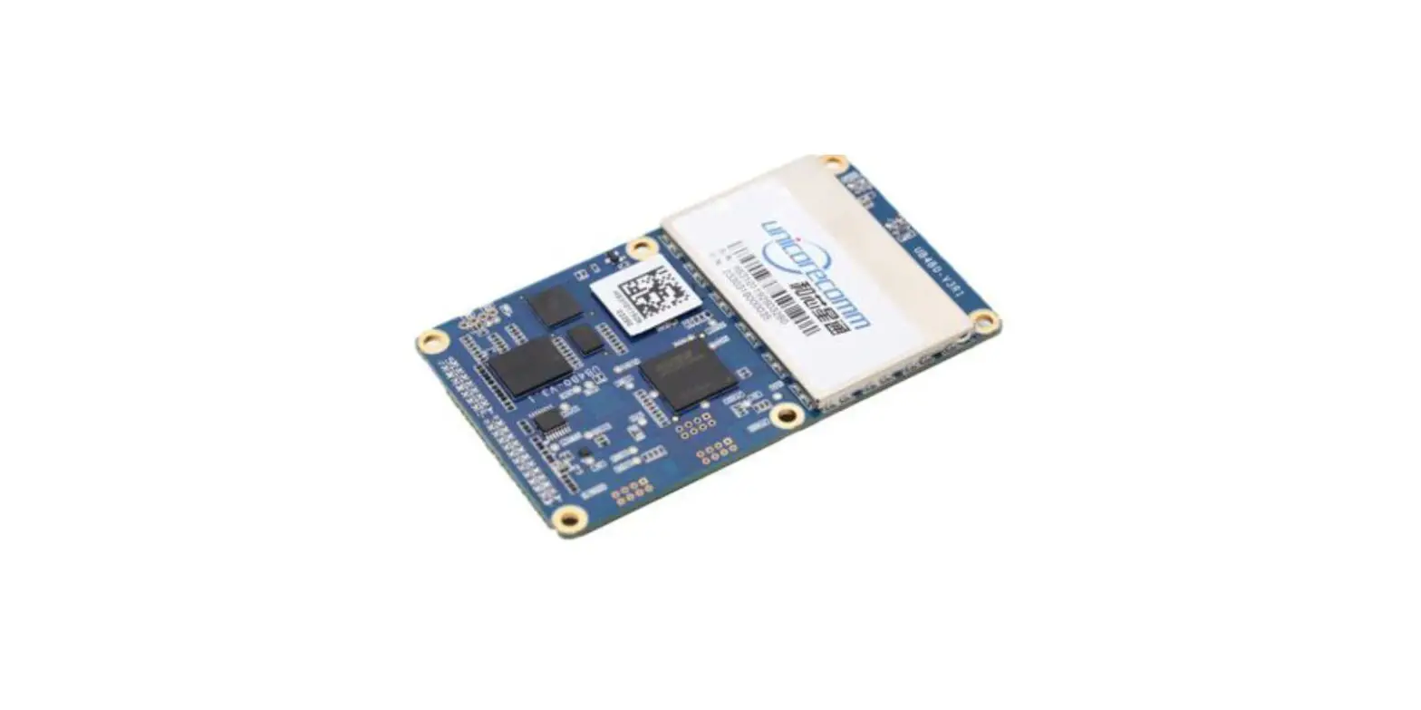
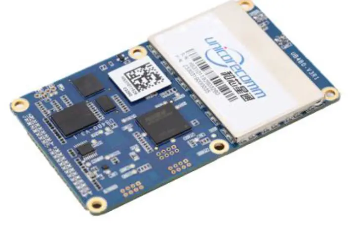
unicorecomm UB4B0 GNSS High Precision Board
The UniCoreComm UB4B0 is a high precision GNSS board that provides millimeter-level carrier-phase observation data and centimeter-level RTK position output. It supports advanced multi-path mitigation and low angle tracking and is suitable for high-precision surveying and mapping applications such as geodetic surveying, engineering survey, deformation monitoring, mechanical control, meteorological monitoring, precision agriculture, continuous operation reference station (CORS), advanced instantaneous RTK, and long-distance RTK.
Key Features
- Based on NebulasII new generation multi-system multi-frequency high-performance SoC
- 432 super-channels and a dedicated fast-acquisition engine
- Supports BDS, GPS, GLONASS, Galileo and QZSS, etc.
- Hardware size compatible with current GNSS OEM boards
- Supports GPS/BDS/GLONASS/Galileo single-system positioning and multi-system positioning
- Supports advanced multi-path mitigation and low angle tracking
- Supports rover station RTK
- Millimeter-level carrier-phase observation data
- High reliability, high stability, suitable for challenging environment
- Supports RS232, Ethernet, 1PPS, external clock input
Installation and Operation User Manual
To install and operate the UniCoreComm UB4B0 GNSS board, please refer to the user manual available at www.unicorecomm.com
Revision History
| Version | Revision History | Date |
| Ver. 1.0 | First release | Aug. 2017 |
| Ver. 1.1 | Update the Dimension of UB4B0 | Feb.2019 |
| R1.3 | Revise mechanical spec/add HW design notes/remove MEMS info | 2019-08-28 |
| R1.4 | Add the shield dimension | 2019-10-12 |
| R2.0 | Align the installation diagram with HW ver3.1 | 2020-02-20 |
| R2.1 | Update Copyright time | 2020-04-07 |
| R2.2 | Update BDS frequency | 2020-06-30 |
| R2.3 | Fix typo and update BDS/GPS frequencies | 2020-10-22 |
| R2.4 | Add the table of absolute maximum rating | 2021-04-09 |
| R2.5 | Correct the indicating sequence of the LED indictor in Chapter 4 | 2021-07-06 |
| R2.6 | Delete the remaining information about MEMS; Update the maximum value of power supply | 2021-08-06 |
Disclaimer
Information in this document is subject to change without notice and does not represent a commitment on the part of Unicore Communications, Inc. No part of this manual may be reproduced or transmitted in any form or by any means, electronic or mechanical, including photocopying and recording, for any purpose without the express written permission of a duly authorized representative of Unicore Communications, Inc. The information contained within this manual is believed to be true and correct at the time of publication.
© Copyright 2009-2021 Unicore Communications, Inc. All rights RSV.
Foreword
This <User Manual> offers you information in the features of the hardware, the installation, specification and use of UNICORECOMM UB4B0 product.
This manual is a generic version. Please refer to the appropriate part of the manual according to your purchased product configuration, concerning CORS, RTK and Heading.
Readers it applies to
This <User Manual> is applied to the technicists who know GNSS Receiver to some extent but not to the general readers
Overview
Thanks for purchasing and using UB4B0 GPS/BDS/GLONASS/Galileo All-Constellation All-Frequency High Precision OEM Board. The board employs the new generation
all-constellation multi-core high precision SoC—NebulasII (432 channel tracking), which is based on the mature baseband technology, with 55nm low power consumption, in which built the broadband ADC and anti-interference unit, integrating two 600MHz ARM processors and a special high-speed floating-point processor, and providing more powerful satellite navigation signal process ability.
UB4B0 provides millimeter-level carrier-phase observation data and centimeter-level RTK position output, supports advanced multi-path mitigation and low angle tracking; UB4B0 is suitable for high precision surveying and mapping application, especially for geodetic surveying, engineering survey, deformation monitoring, mechanical control, meteorological monitoring, precision agriculture, continuous operation reference station (CORS), advanced instantaneous RTK and long-distance RTK, etc.
Key Features
- Based on NebulasII new generation multi-system multi-frequency high-performance SoC
- 432 super-channels and a dedicated fast acquisition engine
- Support BDS, GPS, GLONASS, Galileo and QZSS, etc.
- Hardware size compatible with current GNSS OEM boards
- Support GPS/BDS/GLONASS/Galileo single-system positioning and multi-system positioning
- Support advanced multi-path mitigation and low-angle tracking
- Support rover station RTK
- Millimeter-level carrier-phase observation data
- High reliability, high stability, suitable for a challenging environment
- Support RS232, Ethernet, 1PPS, external clock input
Hardware Design in Considerations
To keep UB4B0 functioning normally, the following signals need to be connected correctly:
- The module’s VCC shoul d b e monotonic, when powered on, the initial level shoul d, be lower than 0.4V, and the undershoot and ringing should be guaranteed within 5%VCC
- It is recommended to use a power chip with current output capacity greater than 2A to power the board
Installation
This section contains the list of the product package and the details of product installation.
Package Inspection
Please check the contents of the package carefully after receiving the package of UB4B0:
- UB4B0 board and EVK suite (or evaluation board) (or enclosure)
- User manual (CD attached)
- Command manual (CD attached)
- UPrecise software (CD attached)
- MMCX antenna cable
- Cross serial port cable
ESD Protection
A lot of components on UB4B0 are susceptible to electrostatic damage, which affects IC circuits and other components. Please follow the instructions below for ESD protection before open the plastic package:
- Electrostatic discharge (ESD) can damage components. Please use an anti-static work bench, a conductive foam pad, and at the same time, wearing an anti-static wrist strap. If ESD workstation is not available, wear an anti-static wrist strap and attach it to metal parts of your industrial PC in order to obtain protection against static electricity.
- Please use the edge of the board, avoiding to touch the components on the board while fetching or putting the boards
- Please carefully check for obviously loose or damaged components after removing the package from the boards. If you have any questions, please contact your local dealer.
Please save the package boxes and plastic containers for storage and transport.
Board Overview
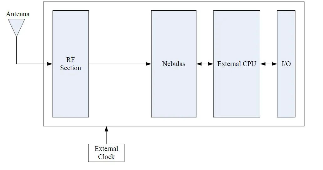
RF Part
The receiver gets filtered and enhanced GNSS signals from the antenna via a coaxial cable. The RF part converts the RF input signals into the IF signals, and converts IF analog signals into digital signals required for NebulasII chip (UC4C0).
NebulasII SoC (UC4C0)
NebulasII (UC4C0) is Unicore’s new generation high precision GNSS SoC with 55nm low power design, supports up to 12 digital intermediate frequency or 8 analog intermediate frequency signals, which can track 12 navigation signals with 432 channels.
1PPS
UB4B0 provides 1 PPS with adjustable pulse width and polarity and 1 output pulse width.
Event1
UB4B0 provides 1 Event Mark Input.
I/O
Power input, data communication port, pulse trigger, LED etc.
Installation Guide
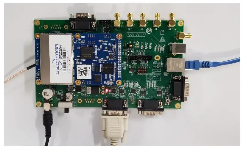
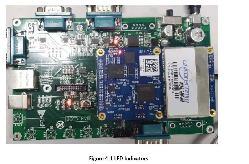
UB4B0 is delivered as a board, users can flexibly assemble according to the scenario and the market need. Figure below shows the typical installation of UB4B0 with evaluation kit (EVK), users can also use other enclosures to install receiver, using the same method.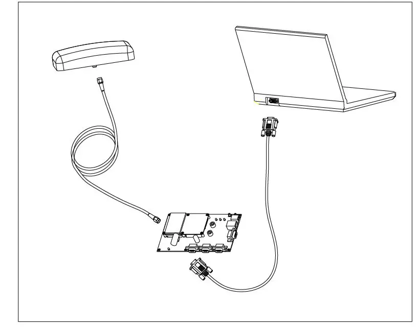
For efficient installation, please prepare the following items before installation:
- UB4B0 EVK suite (or evaluation board) (or enclosure)
- User manual
- Command manual
- UPrecise software (CD attached)
- Qualified antenna
- MMCX antenna cable
- PC or Laptop with serial ports (Win7 and above), with UPrecise installed
After the above preparation is made, please follow the steps below to install:
Following the steps below to install the device:
- Align UB4B0 positioning holes and pins with EVK, and fix UB4B0 on the EVK. EVK provides power supply and standard communication interface for the board, to communicate with peripheral devices (such as PC, USB devices2, and so on).

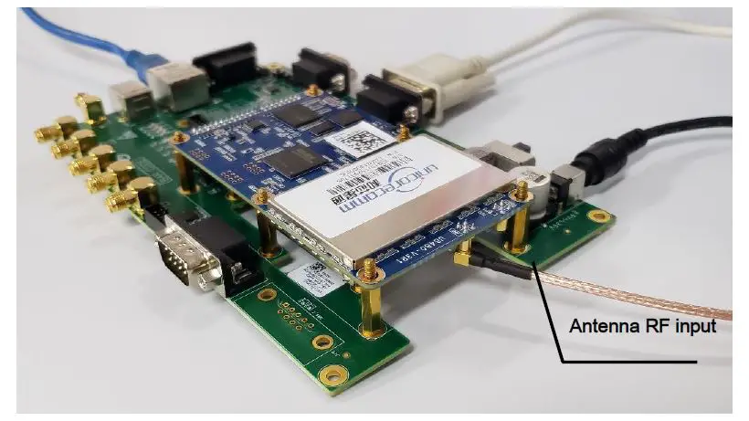
- Select a GNSS antenna with appropriate gain, and mount it in an open sky area. Connect the antenna to J1 MMCX port of UB4B0 via coaxial RF cable.

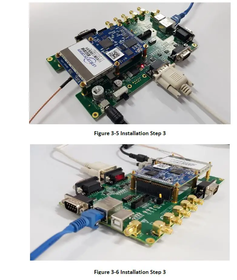
NOTE: The RF connector on the board is MMCX, please select the appropriate cable. The signal gain to the RF connector should be within 25 to 35dB. The Antenna connector provides 5V DC antenna feed. - Connect the PC with EVK through serial ports, or through Ethernet ports.

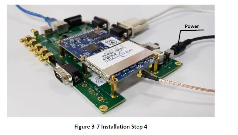
- Connect a 12V adapter with the EVK power input, and switch on to power the device

- Start UPRECISE on the PC
- Refer to UPRECISE online help to send commands or log data for the receiver
Note: If the board has not been in use for a long time, or the distance between the last location and the current location is above 1000 km, a slower fix may occur. In that case, please use the FRESET command to clear the older ephemeris and Almanac information (this command will also clear the Board setup information). After the FRESET command is executed, the board will be reset, it will take 15 minutes to collect new ephemeris and Almanac information.
LED Indicators
| No | Status | Red | Green | Remark | |
| 1 | Single Point Positioning | BDS | Off | 0.25s | Green Fast Flash |
| 2 | Multi-System | 0.25s | 0.25s | Orange Fast Flash (red and green on) | |
| 3 | Differential Positioning | BDS | Off | 1s | Green Slow Flash |
| 4 | Multi-System | 1s | 1s | Orange Slow Flash (red and green on) | |
| 5 | Insufficient satellites | 1s | Off | Red Slow Flash | |
| 6 | Status Switch | Blank 1s | Blank 1s | Time interval between two positioning status | |
| 7 | Abnormal | 0.25s | Off | Red Fast Flash, abnormal status other than 1-5 | |
| No | Status | Red | Green | Remark |
| 8 | Power on | Red Stead on | Off | Switch into other status after starting up. |
There is a double-color LED indicator on UB4B0, which can indicate the working status of the board.
- For normal status, the indicating sequence is: power on status switch insufficient satellites –> status switch single point positioning –> status switch differential positioning status switch –> differential positioning
- If abnormal status occurs on the board, the indicating sequence is: power on –> abnormal, or normal –> abnormal

PC Utility Configuration UPrecise
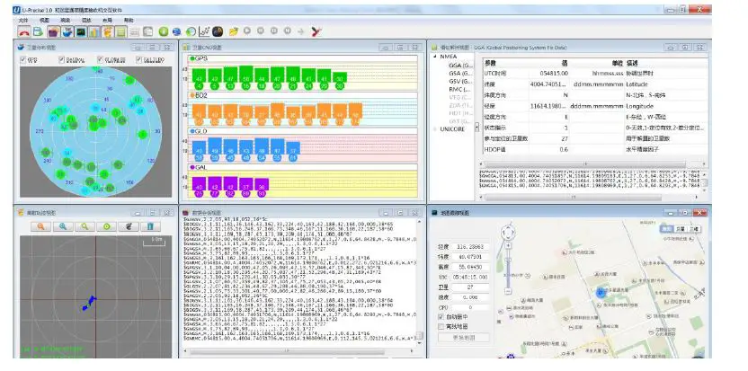
Overview
UB4B0 Unicore UPREC ISE (Control and Display Tool) provides a user-friendly graphical interface to control and display the operation of your receiver. User can access the functionality and information just through several clicks
The following features are included in UPRECIS E
- Connecting the receiver, configuring the baud rate
- The graphic window for displaying the Position of satellite, PRN, and Signal/Noise Ratio (Constellation
- Displaying the historical and present Trajectory of the receiver as well as the position velocity, and time Trajectory View
- Graphic interface for data logging, sending commands to the Receiver Logging Control View
- Console window for sending a command to the receiver (Console
- Sending commands to the Receiver
- The trajectory view for displaying the pre-sent point and the past point of the Receiver
- Upgrading the firmware
- TTFF test

Operation Steps
- Follow the tutorial to install the board, and turn on the EVK switch
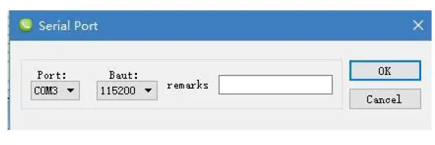
- Click file -> connect the serial port, set the baud rate, the default baud rate is 115200bps

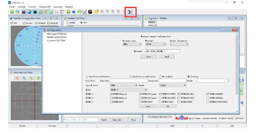
- Click the receiver settings button to configure the NMEA message output. It is recommended to configure GPGGA, GPGSV, and other messages.

- Click the receiver settings button, configure the NMEA message output, and click send. It is recommended to configure GPGGA, GPGSV, and other statements. or
- In the dialog window, click on “Send all Message” to complete all the NMEA message output (update rate 1Hz). Right-click in the dat session window to adjust: output log font size, stop/resume log output, or clear log content
- Configure or type commands according to requirements in various UPrecise views
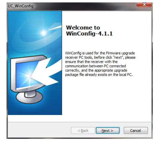
Firmware Update WinConfig
WinConfig (in the attached CD) software is used for the remote update of UB 4B0 , please follow the steps below to install the software:
During the firmware update of the board, please stop all the operations to the device, including the cutoff of the power supply.
- Step 1: Click the program icon to run the software:

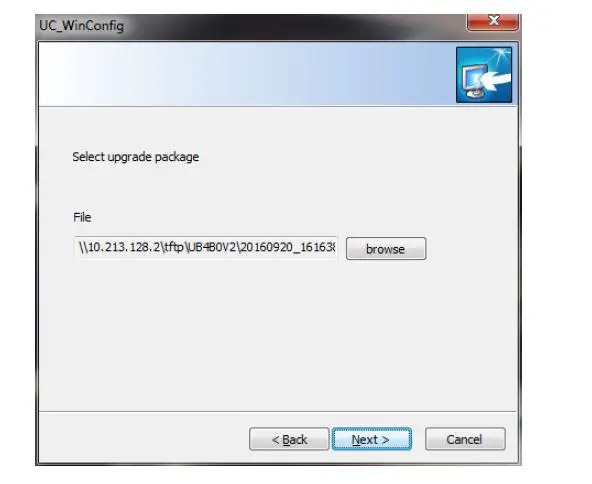
- Step 2: Click “Next” to browse the firmware update package:

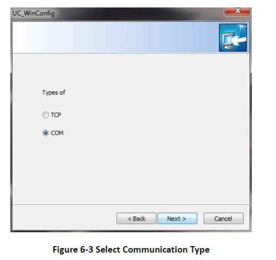
- Step 3: Click “Next” to display the communication type:

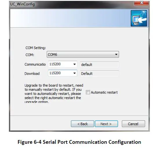
- Step 4 Select the communication type as through Serial Port (COM), click “Next” to configure:

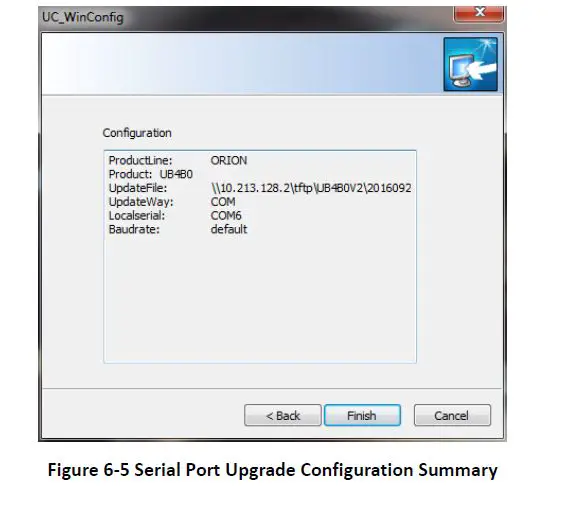
Please use COM1 to update firmware - Step 5: After the configuration of the COM port, click “Next” to prompt the configuration summary dialog:

- Step 6 Check the summary to make sure the receiver is correctly configured, then click “Finish” to prompt the Upgrade

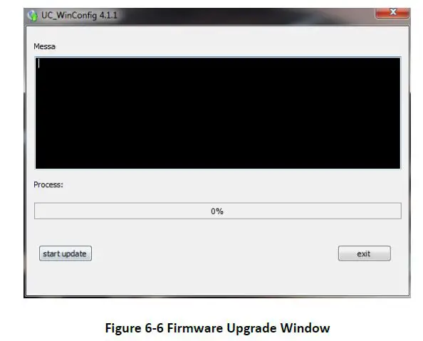
- Step 7: Click “Upgrade” to start the firmware upgrading process:

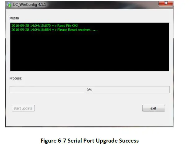
The “Upgrade” button is gray and can’t be clicked while the receiver is in the upgrading process, unless the upgrade is complete, or an error occurs during the upgrade process - Step 8: Check if the firmware upgrading process is finished successfully
Hardware Interface
This chapter is a brief introduction about UB4B0 receiver I/O port and Electrical Characteristics please connect correctly to avo id unnecessary damage
Absolute Maximum Rating
| Item | Pin | Min | Max | Unit |
| Power Supply (VCC) | Vcc | -0.3 | 3.6 | V |
| VCC Ripple (Rated Max.) | Vrpp | 0 | 50 | mV |
| LVTTL Voltage Input | Vin | -0.3 | 3.6 | V |
| Antenna RF Input Power Consumption | ANT_IN input power | +15 | dBm |
Power Input
| Index | Description |
| Acceptable Velocity Input Range | 3.3V +5%/-3% |
Note: Please avoid switching power supply frequently, it is recommended that the switching interval is more than 5s.
RF Input
| Index | Description |
| RF Input | -85 dBm ~ -105 dBm |
| Signal Input | BDS B1I/B2I/B3I/B1C/B2a/B2b*+GPS L1/L2C/L2P(Y)/L5+GLONASS L1/L2+Galileo E1/E5a/E5b |
| LNA power supply | +4.75 ~ +5.10 VDC, 0 ~ 100 mA |
External Clock Input
| Index | Description |
| External Clock Input | Frequency: 10 MHz Voltage Peak: 1.2V~1.8V Frequency Stability: max ± 0.5 ppm Waveform: Sine |
Serial Port Access
| Index | Description |
| Baud Rate | 115200bps by default |
Note: When configuring the serial port, make sure that the baud rate matches the data amount and confirm that the baud rate set by your hardware device is supported. Otherwise, an error may occur.
Pin Function
UB4B 0 provides dual row 2×12 pin 2.0mm pitch as main interface.
As follows: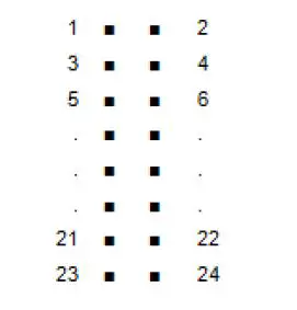
| No | Signal | Type | Description | Note |
| 1 | GND | Ground | Ground Reference | |
| 2 | RTK LED | Output | RTK LED | LVTTL, high level effective |
| 3 | Reserved | RSV | RSV | RSV |
| 4 | PPS | Output | Time Mark Output | LVTTL |
| 5 | VCC | Power | Supply Voltage, +3.3V | +5%/–3% |
| 6 | VCC | Power | Supply Voltage, +3.3V | +5%/–3% |
| 7 | Rx3 or Event2 | Input | External Event 2 Default: COM3 Receive Data | LVTTL |
| 8 | Event1 | Input | External Event 1 | LVTTL |
| 9 | ERROR | Output | Error Detected LED | LVTTL, Low Level effective |
| 10 | Satellite LED | Output | Satellite LED | LVTTL, Low Level effective |
| 11 | CTS2 | Input | COM2 Clear to Send | LVTTL |
| 12 | RESETIN | Input | Hardware reset | LVTTL, Low Level effective, duration >5ms |
| 13 | RTS2 | Output | COM2 Request to Send | LVTTL |
| 14 | RxD2 | Input | COM2 Receive data | LVTTL |
| 15 | CTS1 | Input | COM1 Clear to Send | RS-232 |
| 16 | TxD2 | Output | COM2 transmit data | LVTTL |
| 17 | RTS1 | Output | COM1 Request to Send | RS-232 |
| 18 | RxD1 | Input | COM1 receive data | RS-232 |
| No | Signal | Type | Description | Note |
| 19 | TxD3 or GPIO0 | Input/Output | General Purpose I/O Default: COM3 Transmit Data | LVTTL |
| 20 | TxD1 | Output | COM1 transmit data | RS-232 |
| 21 | USB D (-) | Input/Output | USB D – | |
| 22 | USB D (+) | Input/Output | USB D+ | |
| 23 | GND | Ground | GND | |
| 24 | GND | Ground | GND |
In addition
UB4B0 provides a 10/100M Ethernet interface CAN Odometer interface with dual row 2×8 pin 2.0mm pitch
As follows: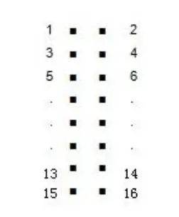
| No. | Signal | Function | Description |
| 1 | ETH_RD- | Negative electrode of Ethernet receiving data, Differential pair. | Connect to RD- |
| 2 | ETH_RD+ | Positive electrode of Ethernet receiving data, Differential pair | Connect to RD+ |
| 3 | CENT_RD | Ethernet interface transformer center receives taps | Connect to RD Center Tap |
| 4 | ETH_TD+ | Positive electrode of Ethernet receiving data, Differential pair | Connect to TD+ |
| 5 | ETH_TD- | Negative electrode of Ethernet receiving data, Differential pair. | Connect to TD- |
| 6 | CENT_TD | Ethernet interface Transformer center send taps | Connect to TD Center Tap |
| 7 | ETH_LINK | Ethernet interface connect indicator light LOW Level: connection building; High Level: ununited; |
| No. | Signal | Function | Description |
| 8 | ETH_SPD | Ethernet interface network speed indicator LOW Level: 100Mbps High Level: 10Mbps | |
| 9 | GND | Ground | GND |
| 10 | CAN_TX | CAN bus transmit data | |
| 11 | CAN_RX | CAN bus receive data | |
| 12 | Reserved | Reserved | Reserved |
| 13 | GND | Ground | GND |
| 14 | SPEED | Odometer velocity Input3 | |
| 15 | FWR | Odometer direction message Input | |
| 16 | GND | Ground | GND |
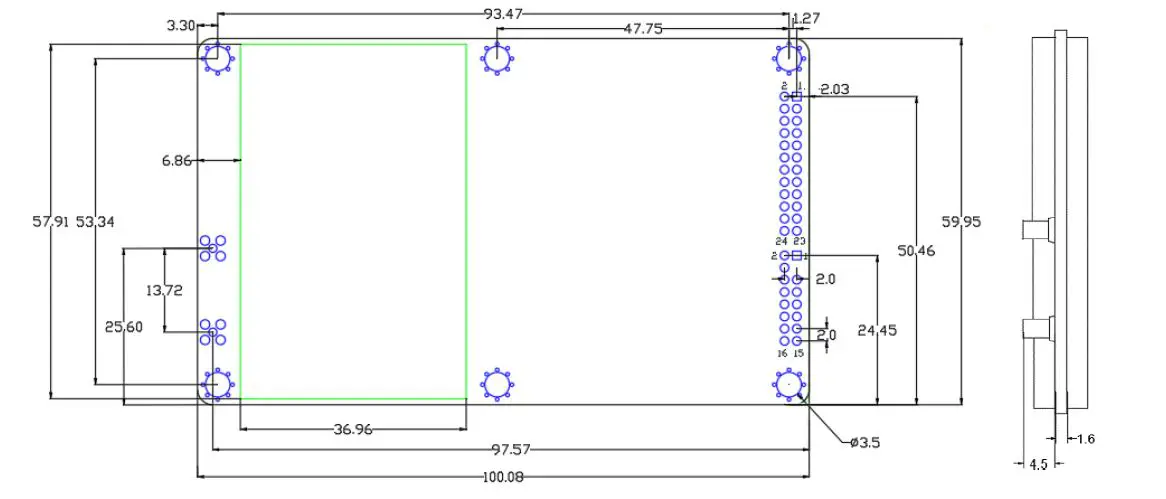
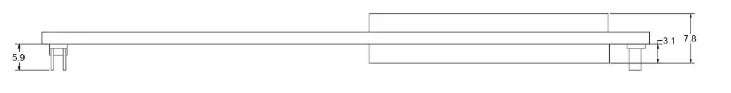
Mechanical drawing
| Parameter | Value | Tolerance |
| Length | 100mm | -0.2mm +0.5mm |
| Width | 60mm | ±0.2mm |
| Height (PCB) | 1.6mm | ±10% |
| RF Connector | 4.5mm | ±0.2mm |
| Shield | 3.1mm | ±0.2mm |
| Pin Height | 5.9mm | ±0.2mm |
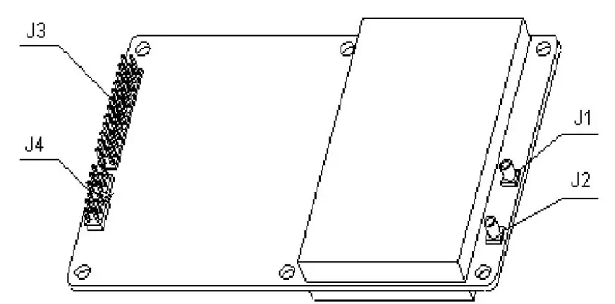
- J1: MMCX female, GNSS antenna interface
- J2: MMCX female,10M external clock interface
- J3: 2×12 dual row pin 2.0mm pitch
- J4: 2x 8 dual row pin 2.0mm pitch
Technical Specifications
Performance Specifications
| Channels | 432 channels, based on NebulasII SoC | Cold Start | <40s | |||
|
Frequency | BDS B1I/B2I/B3I/B1C/B2a/B2b* GPS L1/L2C/L2P(Y)/L5 GLONASS L1/L2 Galileo E1/E5a/E5b QZSS L1/L2/L5 | Hot Start | <10s | |||
| Re-Acquisition | <1s | |||||
| RTK Initialization Time | <5s (Typical) | |||||
| Single Point Positioning (RMS) | Horizontal: 1.5m Vertical: 2.5m | Initialization Reliability | >99.9% | |||
| DGPS (RMS) | Horizontal: 0.4m Vertical: 0.8m | |||||
| RTK (RMS) | Horizontal: 1cm+1ppm Vertical: 1.5cm+1ppm | Differential Data | RTCM 3.2/3.0 | |||
| Data Formats | NMEA-0183, Unicore | |||||
| Measurement Precision (RMS) | BDS GPS GLONASS Galileo | Update Rate | 20Hz | |||
| B1/L1 C/A/E1 code | 10cm | 10cm | 10cm | 10cm | Positioning Update Rate | 20Hz |
| B1/L1/E1 Carrier Phase | 1mm | 1mm | 1mm | 1mm | Time Accuracy (RMS) | 20ns |
| B2/L2P(Y)/L2C /E5a Code | 10cm | 10cm | 10cm | 10cm | Velocity Accuracy (RMS) | 0.03m/s |
| B2/L2P(Y)/L2C /E5a Carrier Phase | 1mm | 1mm | 1mm | 1mm | Network Protocol | NTRIP, HTTP, FTP |
| B3/L5/E5a Code | 10cm | 10cm | 10cm | |||
| B3/L5/E5a Carrier Phase | 1mm | 1mm | 1mm | |||
refers to that B2b is supported with the firmware upgraded
Physical Specifications
| Dimension | 100×60×11.4 mm |
| Weight | 45g |
| Operating Temperature | -40℃~+85℃ |
| Storage Temperature | -40℃~+85℃ |
| Humidity | 95% non-condensing |
| I/O Connectors | 2×12 Pin 2×8 Pin |
| Antenna Input | MMCX |
| External Clock Input | MMCX |
| Vibration | GJB150.16-2009, MIL-STD-810 |
| Shock | GJB150.18-2009, MIL-STD-810 |
Electrical Specifications
| RTC | 3.0~3.3VDC |
| LNA | 4.75~5.10V, 0~100 mA |
| Voltage Ripple | 100mV p-p(max) |
| Power Consumption | 2.8W (typical) |
Functional Ports
| Serial | 1x UART (RS-232), 2 x UART(LV-TTL), 115200bps |
| Internet Access | 1x LAN, 10/100M |
| 1PPS Interface | LV-TTL |
| USB Interface | 1x USB 2.0 Host & Device |
| CAN Interface | 1x CAN |
| Speedometer | 1x wheel pulse 1x heading |
Unicore Communications, Inc.
F3, No.7, Fengxian East Road, Haidian, Beijing, P.R.China, 100094
www.unicorecomm.com
Phone: 86-10-69939800
Fax: 86-10-69939888
[email protected]
www.unicorecomm.com


![U-blox F9 High Precision Gnss Module Datasheet [zed-f9p]](https://static-data1.manualsee.com/1/img/150/15282/2020/12/U-blox-F9-High-Precision-GNSS-Module-Datasheet.jpg "U-blox F9 High Precision Gnss Module Datasheet [zed-f9p]")
![U-blox F9 High Precision Gnss Module Datasheet [zed-f9p]](https://static-data1.manualsee.com/1/img/289/15874/2020/12/U-blox-F9-High-Precision-GNSS-Module.jpg "U-blox F9 High Precision Gnss Module Datasheet [zed-f9p]")


