unicorecomm UM220-IV NL Industry Grade Multi GNSS Positioning Module
Product Information
UM220-IV NL Industry Grade Multi-GNSS Positioning Module
- Revision History: The product has gone through several updates to improve its features and performance parameters since its initial release in Dec. 2017.
- Key Features:
- Multi-GNSS positioning supporting GPS, GLONASS, Galileo, and BeiDou
- High accuracy with up to 1.5-meter CEP (Circular Error Probable)
- Low power consumption
- Compact design
- SMT stencil for easy installation
- Supports multiple output protocols including NMEA and UBX
- Technical Specifications:
- Electrical specifications:
- Power supply: 3.3V to 5.5V DC
- Power consumption: 25mA (tracking mode), 5mA (standby mode)
- Communication interface: UART
- Operation condition:
- Operating temperature: -40℃ to +85℃
- Storage temperature: -40℃ to +105℃
- Operating humidity: 5% to 95%
- Dimensions:
- Size: 14mm x 14mm x 6.5mm
- Weight: 1.3g
- Pin definition:
- VCC: power supply input
- GND: ground
- RX: receive data
- TX: transmit data
- PPS: pulse per second output
- ANT: antenna input
- V_BCKP: backup power supply
- Electrical specifications:
Product Usage Instructions:
- Installation Preparation:
- Ensure the power supply voltage is within the accepted range of 3.3V to 5.5V DC.
- Choose an appropriate location for the module and ensure that the antenna has a clear view of the sky.
- Hardware Installation:
- Solder the module onto the PCB using the SMT stencil provided.
- Connect the antenna to the ANT pin, ensuring that the antenna has a clear view of the sky.
- Connect the power supply to the VCC pin and ground to the GND pin.
- Connect the RX and TX pins to the microcontroller or other device using a UART interface.
- (Optional) Connect the PPS output pin to an external device to synchronize timing.
- Power-On:
- Apply power to the module and wait for it to acquire a satellite signal.
- The module will output positioning data in either NMEA or UBX format through the RX pin, depending on the selected output protocol.
Revision History
| Version | Revision | Date |
| Ver. 1.0.0 Primary | UM220-IV NL User manual Primary. | Dec.2017 |
| Ver. 1.0.1 Alpha release | The Pin definition and performance parameters have been updated. | Jun.2018 |
| Ver. 1.0.2 Beta release | Updated size parameters | Aug.2018 |
| Ver. 1.0.3 Product release | Update product label instruction | May.2019 |
| R1.1 | 1.2: Delete the GLONASS frequency 6.2: Add shelf life | Sep. 2019 |
| R1.2 | Chapter 6.2: revise the MSL instructions | Jan. 2020 |
| R1.3 | Add the footnote to elaborate CEP | Oct. 2020 |
| R1.4 | Add the description of SMT stencil | Jun. 2021 |
| R1.5 | Update power supply VCC and V_BCKP | Aug. 2021 |
| R1.6 | Add the Note in Section 4.3 | Nov. 2021 |
Disclaimer
Information in this document is subject to change without notices and does not represent a commitment on the part of Unicore Communication, Inc. No part of this manual may be reproduced or transmitted in any form or by any means, electronic or mechanical, including photocopying and recording, for any purpose without the express written permission of a duly authorized representative of Unicore Communications, Inc. The information contained within this manual is believed to be true and correct at the time of publication.
© Copyright 2009-2021 Unicore Communications, Inc. All rights reserved.
Foreword
This document offers you information in the features of the hardware, the installation, specification and use of UNICORECOMM UM220-IV NL product.
Reader it applies to
This document is applied to the technicians who know GNSS Receiver to some extent but not to the general readers.
Structure of the file
This document includes the followings:
- Introduction: Briefly explaining the functions, performances and installing of the product
- Installation: Contains the list of the product package and the details of product installation
- Technical Specification: Offering technical specifications of the product
- Hardware Specification: Offering all the information of hardware interface of the product
- Mechanical Features: Offering UM220-IV NL dimensions, layout, and top views.
Introduction
Overview
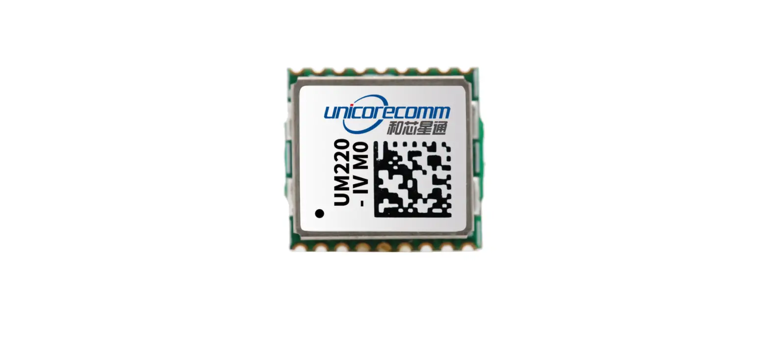
Unicore UM220-IV NL is a multisystem GNSS module. Based on UNICORECOMM low power GNSS SoC-UFirebird designed, and the support of BDS B1+GPS L1 dual system joint positioning or single system joint positioning and the QZSS signal can be received. And support AGNSS. In the case of networking, the positioning speed is improved through UNICORECOMM assist data service. UM220-IV NL is compact in size and uses SMT pads to support fully automatic integration of standard discharge and reflow soldering, especially suitable for low cost and low power consumption fields.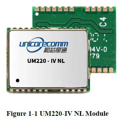
| Module | Model | PN | Standard | System | Interface | Data updating rate | |||||
| Professional | Automotive | GPS | BDS | GLONASS | QZSS | UART1 | UART2 | ||||
| UM220- IV NL | GB | 080101016200 | ● | ● | ● | ● | ● | ● | 1Hz | ||
Key Features
| Power | ||||
| Voltage | +3.0~3.6 VDC | |||
| Power consumption1 | 50mW | |||
| RF Input | ||||
| Input VSWR | ≤1.5 | |||
| Input impedance | 50Ω | |||
| Antenna gain | 15~30dB | |||
| Physical Characters | ||||
| Dimension | 16.0*12.2*2.4mm | |||
| Weight | 0.8g | |||
| Environment | ||||
| Operating Temperature | -40℃ ~ +85℃ | |||
| Storage Temperature | -45℃ ~ +90℃ | |||
| RoHS | Accord | |||
| Input/ Output Data Interface | ||||
| UART | 2 UART, LVTTL. Baud rate 4800~115200bps | |||
| GNSS Performance | ||||
| Frequency | BDS B1:1561.098MHz GPS L1 :1575.42MHz | |||
| TTFF | Cold Start:28s Hot Start:1s Reacquisition:1s AGNSS2:4s | |||
| Positioning accuracy3 | 2.0m (Dual system Horizontal, Open sky) 3.5m (Dual system vertical, Open sky) | |||
| Velocity accuracy (RMS) | 0.1m/s(Dual system Horizontal, Open sky) | |||
| Sensitivity4 | GN | BDS | GPS | |
| Tracking | -160dBm | -159dBm | -160dBm | |
| Acquisition | -147dBm | -146dBm | -147dBm | |
| Hot Start | -151dBm | -150dBm | -151dBm | |
| Reacquisition | -158dBm | -157dBm | -158dBm | |
| 1PPS(RMS) 5 | 20ns | |||
| Data update rate | 1Hz | |||
| Data Output6 | NMEA 0183,Unicore Protocol | |||
- Continuous positioning typical value
- Timely input of assist data
- CEP, 50%
- When C/N0 is 41db
- 1 hour statistics, timing is not recommended.
- User can be configured refer to《 Unicore NPL Protocol Specification Ver.3.1》 document or update version for details
Interface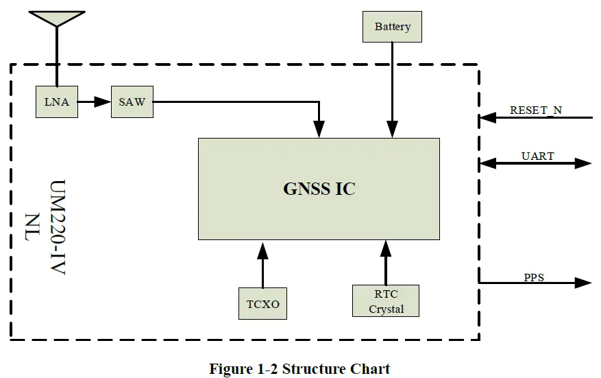
UART
UM220-IV NL module COM1 is the primary serial port, which supports data transfer and firmware upgrade function. The signal input/output level is LVTTL. The default baud rate is 9600bps, and is adjustable, can be configured up to 115200bps. During design in, please ensure that COM1 is connected to a PC or an external processor for firmware upgrades.
COM2 only supports data transmission, and cannot be used for firmware upgrade purpose, reserved for future use.
1PPS
UM220-IV NL outputs 1PPS with adjustable pulse width and polarity.
Product Installation
Installation Preparation
UM220-IV NL Modules are Electrostatic Sensitive Devices and require special precautions when handling:
- Follow the steps in section 2.2 in the correct order
- Electrostatic discharge (ESD) may cause damage to the device. All operations mentioned in this chapter shall be carried out in an antistatic workbench, using both wearing an antistatic wrist strap and a conductive foam pad. If antistatic workbench is not available, wear an antistatic wrist strap and connect the other end to a metal frame to play a role in anti-static
- Hold the edge of the module, not in direct contact with the components
- Please check carefully whether the module has obviously loose or damaged components. If you have questions, please contact us or your local dealer.

Please check the contents of the package carefully after receiving the package of UM220-IV NL:
- UM220-IV NL EVK suite(with AC Adapter)
- UM220-IV NL User manual
- uSTAR application package
- Qualified antenna
- Antenna connection cable
- Direct serial cable
- PC or Laptop with serial ports (Windows 2000/xp/win7)
Hardware Installation
After the above preparation is complete, follow the steps below to install:
- Step 1: Make sure to make full anti-static measures, such as anti-static wrist strap, grounding the workbench;
- Step 2: Open the UM220-IV NL evaluation kit;
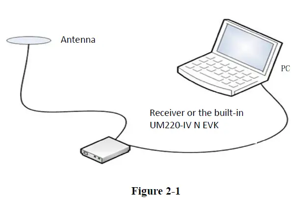
- Step 3: Select the GNSS antenna with appropriate gain, fix it in the non-block area, using the appropriate cable to connect the antenna with UM220 EVK;
- Step 4: Connect the PC to the EVK serial port through direct serial cable;
- Step 5: Power the evaluation board and initialize the UM220-IV NL;
- Step 6: Open the uSTAR
- Step 7: Controlled the receiver through uSTAR to display constellations view, log messages, and receiver status.
Technical Specifications
Electrical Specifications
Absolute Maximum Rating:
| Item | Pin | Min | Max | Unit | Condition |
| Power Supply (VCC) | Vcc | -0.5 | 3.6 | V | |
| VCC Ripple | Vrpp | 50 | mV | ||
| Digital IO | Vin | -0.5 | Vcc +0.2 | V | |
| Storage Temperature | Tstg | -45 | 90 | ℃ | |
| MSL | □Level 1 □Level 2 ■Level 3 □TBD | ||||
Operation Condition
| Pin | Min | Typical | Max | Unit | Condition | |
| Power Supply(Vcc) | Vcc | 3.0 | 3.3 | 3.6 | V | |
| Peak Current | Iccp | 28 | mA | Vcc = 3.0 V | ||
| Tracking Average Current | IACQ | 15 | 17 | 19 | mA | Vcc = 3.0V |
| Low Level Input Voltage | Vin_low | 0.7 | V | |||
| High Level Input Voltage | Vin_high | 1.2 | V | |||
| Low Level Output Voltage | Vout_low | 0.4 | V | Iout = -8 mA | ||
| High Level Output Voltage | Vout_high | Vcc–0.4 | V | Iout = 8 mA | ||
| Antenna Gain | Gant | 15 | 30 | dB | ||
| Noise Figure | Nftot | 2 | dB | |||
| Operating Temperature | Topr | -40 | 85 | ℃ |
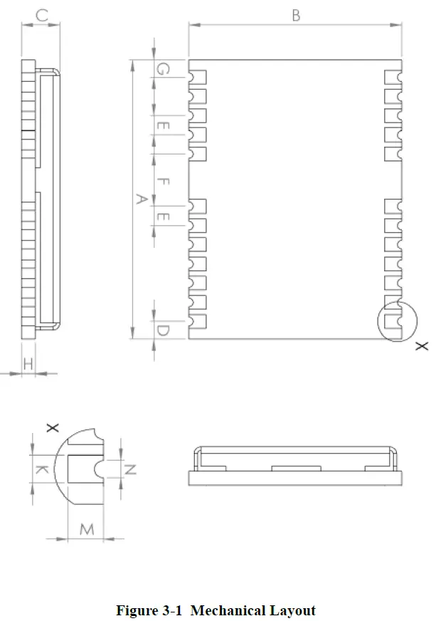
Dimensions
| Symbol | Min(mm) | Type(mm) | Max(mm) |
| A | 15.9 | 16.0 | 16.5 |
| B | 12.05 | 12.2 | 12.35 |
| C | 2.2 | 2.4 | 2.6 |
| D | 0.9 | 1.0 | 1.3 |
| E | 1.0 | 1.1 | 1.2 |
| F | 2.9 | 3.0 | 3.1 |
| G | 0.9 | 1.0 | 1.3 |
| H | 0.7 | 0.8 | 0.9 |
| K (Outside the hole) | 0.7 | 0.8 | 0.9 |
| N (Inside the hole) | 0.4 | 0.5 | 0.6 |
| M | 0.8 | 0.9 | 1.0 |
Pin Definition (Top View)
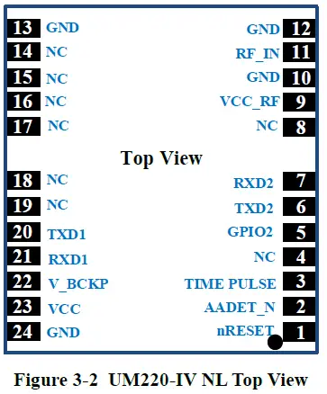
| No | Name | I/O | Electrical level | Description |
| 1 | nRESET | I | LVTTL | For reset, Low level active, if you do not use the pin, please leave it hanging |
| 2 | AADET_N | I | LVTTL | Antenna detection |
| 3 | TIMEPULSE | O | LVTTL | Time pulse(1PPS) |
| 4 | NC | I | LVTTL | reserve |
| 5 | GPIO2 | I | LVTTL | Antenna detection |
| 6 | TXD2 | O | LVTTL | UART 2-TX |
| 7 | RXD2 | I | LVTTL | UART 2-RX |
| 8 | NC | reserve | ||
| 9 | VCC_RF | O | =VCC | Output voltage RF section |
| 10 | GND | — | Ground | |
| 11 | RF_IN | I | GNSS signal input (BDS B1+GPS L1) | |
| 12 | GND | — | Ground | |
| 13 | GND | — | Ground | |
| 14 | NC | reserve | ||
| 15 | NC | reserve | ||
| 16 | NC | reserve | ||
| 17 | NC | reserve | ||
| 18 | NC | I/O | LVTTL | reserve |
| 19 | NC | I/O | LVTTL | reserve |
| 20 | TXD1 | O | LVTTL | UART 1-TX |
| 21 | RXD1 | I | LVTTL | UART 1-RX |
| 22 | V_BCKP | I | 1.65V~3.6V | Backup voltage supply |
| 23 | VCC | — | 3.0V~3.6 V | Main power |
| 24 | GND | — | Ground |
PCB Packaging

Hardware Design
Design in Considerations
To make UM220-IV NL to work properly, you need to properly connect the following:
- Recommended in serial concatenated RX place 1 K Ω resistance, TX concatenated 33 Ω or 1 KΩ resistance, other need PIO concatenated 4.7 K resistor in the pin.
- Connect all the GND pins to ground.
- Connect the RF_IN signal to the antenna, and the line will keep 50Ω impedance matching.
- Ensure COM1 is connected to a PC or an external processor, users can use this serial port to receive position data. COM1 is also necessary for firmware upgrades.
In order to obtain good performance, special concern should be paid during the design:
- Power supply: Stable and low ripple power is necessary for good performance. Make sure the peak to peak voltage ripple does not exceed 50mV.
- Using LDO to ensure the purity of power supply
- Try to place LDO close to the module in layout
- Widening the power circuit or use copper pour surface to transmit current
- Avoid walking through the high-power or high inductance devices such as magnetic coil
- UART interfaces: Ensure that the signals and baud rate of main equipment match UM220-IV NL module’s
- Antenna interface: Make sure the antenna impedance matching, and the circuit is short and smooth, try to avoid acute angle
- Antenna position: In order to ensure a good signal-to-noise ratio, the antenna is well isolated from the electromagnetic radiation source, especially the electromagnetic radiation in the frequency range of 1559 ~ 1607MHz
- Try to avoid circuits below UM220-IV NL
- This module is a temperature sensitive device, dramatic changes in temperature will result in reduced performance, keep it as far away from the high-power hightemperature air and heating devices as possible.
Avoid Power Connection
Module input port (UM220-IV NL including: RXD, GPIO) when the module is not powered on, if there is data input in the above port, it will form a series of power on the module VCC. When the series voltage is higher than 1.6v, it may cause the failure of starting up when the module is powered on.
Solution: When the module is not powered on, make sure that the IO port connected by the module is in a high-resistance state or a low level to avoid power connection. Or in the serial concatenated 1KΩ resistor RX, TX concatenated 33Ω or 1K resistor, other need PIO concatenated 4.7KΩ resistor in the pin.
Antenna
If UM220-IV NL used the +3V active antenna, suggest use the VCC_RF pin output is recommended to power the antenna through feed inductance.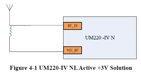
Note: If the user has a high requirement for ESD (> ± 2000 V), the user should consider other method to feed the antenna rather than using the VCC_RF pin. In this case, it is recommended to choose a power supply chip with high ESD protection level. Gas discharge tube, varistor, TVS tube and other high-power protective devices may also be used in the power supply circuit to further protect the module from ESD damage or other Electrical Over-Stress (EOS).
If the UM220-IV NL uses an active antenna other than +3V, the bias voltage required by the antenna V_BIAS is supplied to the antenna through a feed inductor.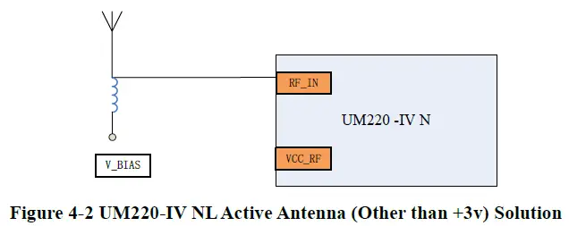
If UM220-IV NL uses passive antenna, the antenna is directly connected to RF_IN pin, while VCC_RF can be suspended. It should be noted that the use of passive antennas may cause a decrease in GNSS performance compared to active antennas.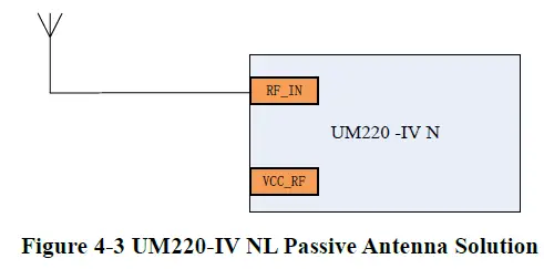
Serial Port
UM220-IV NL have two LVTTL serial port, for PC connection, please use a RS232 voltage level converter.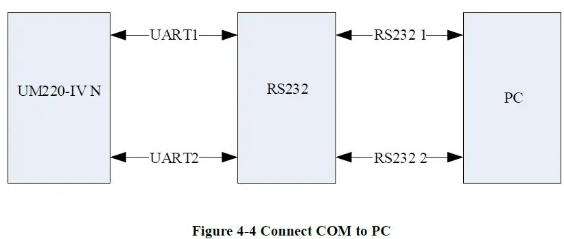
Disassembly
When it is necessary to remove the module, it is recommended to melt the soldering tin of the pins on both sides of the module with an electric soldering iron and remove the module with tweezers. Do not use other means to remove the module (such as hot air gun blowing module), may lead to module damage.
Package
Product Label Description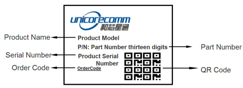
Package D escription
The UM220-IV NL module is packaged in vacuum sealed aluminum foil anti-static bag with desiccant and moisture-proof agent. When using reflow welding process to weld modules, please strictly comply with IPC standard to conduct humidity control on modules. As packaging materials such as carrier belt can only withstand the temperature of 65 degrees Celsius, modules shall be removed from the packaging during baking. A small number of samples (usually by hand welding) are shipped in an electrostatic bag, since manual welding does not need to consider the problem of humidity, so no additional moisture protection.
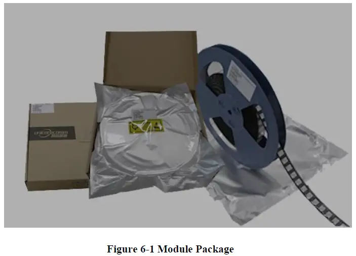
| Item | Description |
| Module | 500pics/reel |
| Reel size | workpiece tray: 13″ external diameter 330mm, internal diameter 100mm, wide 24mm, thickness 2.0mm |
| Carrier tape | Space between: 20mm |
Check the humidity indicator card before soldering. The 30% indication is blue for normal conditions, as shown in figure 6 2. Bake modules firstly before soldering if the 30% indication turns pink, as shown in figure 6 3. The UM220 IV M modules are rated at MSL level 3, for more MSL information, please refer to www.jedec.org.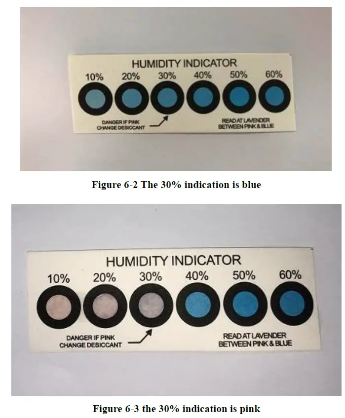
The shelf life of UM220-IV NL is one year.
Clean
Do not use alcohol or other organic solvents to clean, it may lead to fluk residues into the shielding shell, causing mildew and other problems.
Reflow Soldering
In order to avoid device falling off, the module should be placed on the top of the main board during welding. Reflow soldering temperature curve is recommended as shown in figure 8-1 below (M705-GRN360 is recommended for solder paste). Figure 8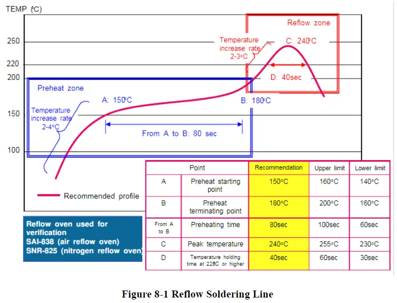
Note: The apertures in the stencil need to meet the customer’s own design requirements and inspection specifications, and the thickness of the stencil should be above 0.15mm, and 0.18mm is recommended.
Unicore Communications, Inc.
F3, No.7, Fengxian East Road, Haidian, Beijing, P.R.China, 100094
www.unicorecomm.com
Phone: 86-10-69939800
Fax: 86-10-69939888
[email protected]
www.unicorecomm.com


