
Qubino
Flush On/Off Thermostat 2
SKU: GOAEZMNKID1


Quickstart
This is a
secure
HVAC-Thermostat
for
Europe.
To run this device please connect it to your mains power supply.
To add this device to your network execute the following action:
SmartStart Inclusion
Classic Inclusion
1. Enable add/remove mode on your Z-Wave gateway (hub)
Important safety information
Please read this manual carefully. Failure to follow the recommendations in this manual may be dangerous or may violate the law.
The manufacturer, importer, distributor and seller shall not be liable for any loss or damage resulting from failure to comply with the instructions in this manual or any other material.
Use this equipment only for its intended purpose. Follow the disposal instructions.
Do not dispose of electronic equipment or batteries in a fire or near open heat sources.
What is Z-Wave?
Z-Wave is the international wireless protocol for communication in the Smart Home. This
device is suited for use in the region mentioned in the Quickstart section.

Z-Wave ensures a reliable communication by reconfirming every message (two-way
communication) and every mains powered node can act as a repeater for other nodes
(meshed network) in case the receiver is not in direct wireless range of the
transmitter.
This device and every other certified Z-Wave device can be used together with any other
certified Z-Wave device regardless of brand and origin as long as both are suited for the
same frequency range.
If a device supports secure communication it will communicate with other devices
secure as long as this device provides the same or a higher level of security.
Otherwise it will automatically turn into a lower level of security to maintain
backward compatibility.
For more information about Z-Wave technology, devices, white papers etc. please refer
to www.z-wave.info.
Product Description
The Qubino Flush On/Off Thermostat 2 can measure the power consumption of the connected electrical device and itself has an extremely low power consumption of just 0.4 W.On/Off Thermostat 2 can operate across a wide temperature range, from a chilly -10″°C to a scorching 40″°C (14 – 104″°F) it allows to create complex scenes and switch any device relative to a set temperature range.
– It supports SmartStart inclusion for quick set up- Automatically turn the device on if the temperature is too low (antifreeze)
– Automatically turn the device on/off based on Hysteresis- Works on 110-240 VAC or 24-30 VDC
Prepare for Installation / Reset
Please read the user manual before installing the product.
In order to include (add) a Z-Wave device to a network it must be in factory default
state. Please make sure to reset the device into factory default. You can do this by
performing an Exclusion operation as described below in the manual. Every Z-Wave
controller is able to perform this operation however it is recommended to use the primary
controller of the previous network to make sure the very device is excluded properly
from this network.
Reset to factory default
This device also allows to be reset without any involvement of a Z-Wave controller. This
procedure should only be used when the primary controller is inoperable.
Safety Warning for Mains Powered Devices
ATTENTION: only authorized technicians under consideration of the country-specific
installation guidelines/norms may do works with mains power. Prior to the assembly of
the product, the voltage network has to be switched off and ensured against re-switching.
Installation
The installation process tested and approved by professional electricians, consists of the following simple steps:
Step 1 “ Turn OFF the fuse:
“ Take extra precautions to avoid accidentally turning the device on during installation.
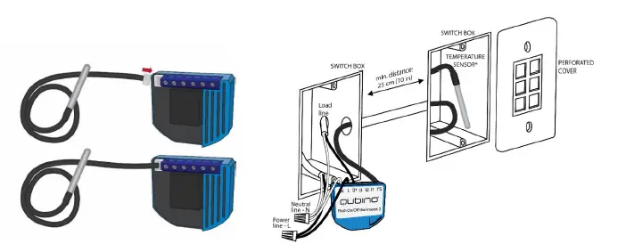
Step 2 “ Installing the device:
“ Connect the device exactly according to the diagrams shown below
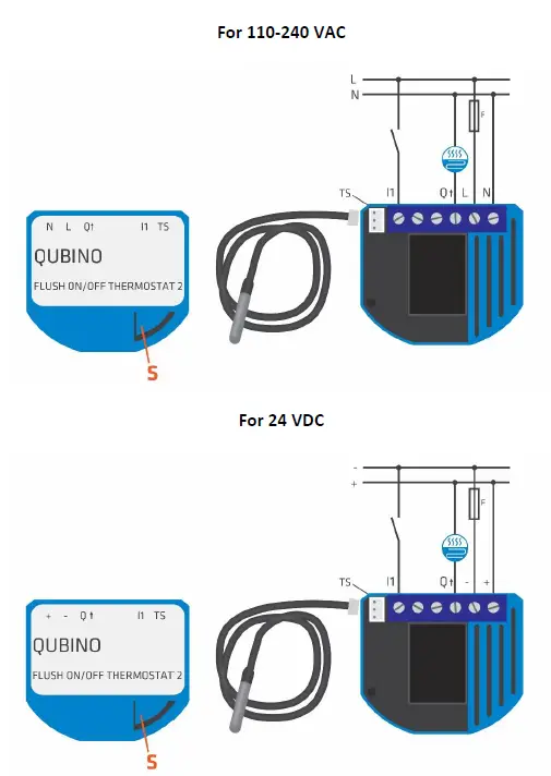
S…” Service button
Qubino Temperature Sensor manual: https://qubino.com/manuals/Installation/Temperature_Sensor_manual.pdf
Inclusion/Exclusion
On factory default the device does not belong to any Z-Wave network. The device needs
to be added to an existing wireless network to communicate with the devices of this network.
This process is called Inclusion.
Devices can also be removed from a network. This process is called Exclusion.
Both processes are initiated by the primary controller of the Z-Wave network. This
controller is turned into exclusion respective inclusion mode. Inclusion and Exclusion is
then performed doing a special manual action right on the device.
Inclusion
SmartStart Inclusion
Classic Inclusion
1. Enable add/remove mode on your Z-Wave gateway (hub)
Exclusion
Quick trouble shooting
Here are a few hints for network installation if things dont work as expected.
- Make sure a device is in factory reset state before including. In doubt exclude before include.
- If inclusion still fails, check if both devices use the same frequency.
- Remove all dead devices from associations. Otherwise you will see severe delays.
- Never use sleeping battery devices without a central controller.
- Dont poll FLIRS devices.
- Make sure to have enough mains powered device to benefit from the meshing
Association – one device controls an other device
Z-Wave devices control other Z-Wave devices. The relationship between one device
controlling another device is called association. In order to control a different
device, the controlling device needs to maintain a list of devices that will receive
controlling commands. These lists are called association groups and they are always
related to certain events (e.g. button pressed, sensor triggers, …). In case
the event happens all devices stored in the respective association group will
receive the same wireless command wireless command, typically a ‘Basic Set’ Command.
Association Groups:
Group NumberMaximum NodesDescription
| 1 | 5 | Lifeline |
| 2 | 5 | Basic set: triggered by change of output Q |
| 3 | 5 | Basic set: triggered when actual temperature reaches Too High or Too Low temperature limit; Heat mode: when temperature reaches Too High Temperature Limit reports OFF (0x00), when temperature reaches Too Low Temperature Limit reports ON (0xFF). Cool mode: when temperature reaches Too High Temperature Limit reports ON (0xFF), when temperature reaches Too Low Temperature Limit reports OFF (0x00). Thermostat off mode reports OFF (0x00) on both limits reached. Hysteresis is 1C. |
| 4 | 5 | Sensor multilevel report: triggered by change of temperature for threshold defined in configuration parameter 120 |
Configuration Parameters
Z-Wave products are supposed to work out of the box after inclusion, however
certain configuration can adapt the function better to user needs or unlock further
enhanced features.
IMPORTANT: Controllers may only allow configuring
signed values. In order to set values in the range 128 … 255 the value sent in
the application shall be the desired value minus 256. For example: To set a
parameter to 200âit may be needed to set a value of 200 minus 256 = minus 56.
In case of a two byte value the same logic applies: Values greater than 32768 may
needed to be given as negative values too.
Parameter 1: Input I1 switch type
With this parameter, you can select between push-button (momentary) and on/off toggle switch types.
Size: 1 Byte, Default Value: 1
SettingDescription
| 0 | push-button (momentary) |
| 1 | on/off toggle switch |
Parameter 4: Input 1 contact type
This parameter determines how the switch or push-button is connected.
Size: 1 Byte, Default Value: 0
SettingDescription
| 0 | NO (normally open) input type |
| 1 | NC (normally close) input type |
Parameter 40: Watt Power Consumption Reporting Threshold for Q Load
Choose by how much power consumption needs to increase or decrease to be reported.
Size: 1 Byte, Default Value: 10
SettingDescription
| 0 | Power consumption reporting disabled |
| 1 – 100 | 1% – 100% Power consumption reporting enabled. New value is reported only when Wattage in real time changes by more than the percentage value set in this parameter compared to the previous Wattage reading, starting at 1% (the lowest value possible). |
Parameter 42: Watt Power Consumption Reporting Time Threshold for Q
Set value refers to the time interval with which power consumption in Watts is reported (3032767 seconds) starting from time of last Watts reported. If for example 300 is entered, energy consumption reports will be sent to the gateway (hub) every 300 seconds (or 5 minutes).
Size: 2 Byte, Default Value: 600
SettingDescription
| 0 | Power consumption reporting disabled |
| 0 – 450 | This parameter defines minimum temperature difference between real measured temperature and set-point temperature to turn device on in heat mode or turn device off in cool mode. |
Parameter 43: Hysteresis Upper temperature offset
This parameter defines minimum temperature difference between real measured temperature and set-point temperature to turn device on in heat mode or turn device off in cool mode.
NOTE1: If configuration parameter 78 (Scale selection) is set to Celsius, then valid interval is 0250 (0.0 C25.0 C, resolution 0.1 C)
NOTE2: If configuration parameter 78 (Scale selection) is set to Fahrenheit, then valid interval is 0450 (0.0 F45.0 F, resolution 0.1 F) NOTE3: If configuration parameter 78 (Scale selection) is set to Fahrenheit, note that Fahrenheit values will be converted to Celsius degrees. Due to conversion algorithm please be advised that configuration value could drift when converting values back and forth.
Size: 2 Byte, Default Value: 5
SettingDescription
| 0 – 450 | This parameter defines minimum temperature difference between real measured temperature and set-point temperature to turn device on in heat mode or turn device off in cool mode. |
Parameter 44: Hysteresis Lower temperature offset
This parameter defines minimum temperature difference between real measured temperature and set-point temperature to turn device off in heat mode or turn device on in cool mode.
NOTE1: If configuration parameter 78 (Scale selection) is set to Celsius, then valid interval is 0250 (0.0 C25.0 C, resolution 0.1 C)
NOTE2: If configuration parameter 78 (Scale selection) is set to Fahrenheit, then valid interval is 0450 (0.0 F45.0 F, resolution 0.1 F)
NOTE3: If configuration parameter 78 (Scale selection) is set to Fahrenheit, note that Fahrenheit values will be converted to Celsius degrees.”
Due to conversion algorithm please be advised that configuration value could drift when converting values back and forth.
Size: 2 Byte, Default Value: 5
SettingDescription
| 0 – 450 | This parameter defines minimum temperature difference between real measured temperature and set-point temperature to turn device off in heat mode or turn device on in cool mode. |
Parameter 45: Antifreeze
Set value determines at which temperature the device will be turned on even (if the thermostat was manually set to off).”
NOTE1: Antifreeze is activated only in heating mode and it uses hysteresis of 0.5C.”
NOTE2: If configuration parameter 78 (Scale selection) is set to Celsius, then valid interval is -125125 (-12.5 C12.5 C, resolution 0.1 C)
NOTE3: If configuration parameter 78 (Scale selection) is set to Fahrenheit, then valid interval is 95545 (9.5 F54.5 F, resolution 0.1 F)
NOTE4: If configuration parameter 78 (Scale selection) is set to Fahrenheit, note that Fahrenheit values will be converted to Celsius degrees.”
Due to conversion algorithm please be advised that configuration value could drift when converting values back and forth.
Size: 2 Byte, Default Value: 50
SettingDescription
| -125 – 545 | Set value determines at which temperature the device will be turned on even (if the thermostat was manually set to off). |
| 1000 | Antifreeze functionality disabled. |
Parameter 59: Thermostat mode
This parameter determines how the device will operate if it will operate in the heating mode or in the cooling mode. The range of the hysteresis will remain the same, only operation will change from heating to cooling and vice versa
NOTE1: After parameter change, first exclude device (without setting parameters to default value) and then re-include the device!
Size: 1 Byte, Default Value: 0
SettingDescription
| 0 | Heat mode |
| 1 | Cool mode |
Parameter 60: Too low temperature limit
This parameter determines the temperature at which the device sends a command to the associated device – to turn ON device or to turn OFF device:
NOTE1: Too low temperature limit is used with Association Group 3.
NOTE2: If configuration parameter 78 (Scale selection) is set to Celsius, then valid interval is -1501000 (-15.0 C100.0 C, resolution 0.1 C)
NOTE3: If configuration parameter 78 (Scale selection) is set to Fahrenheit, then valid interval is 502120 (5.0 F212.0 F, resolution 0.1 F)
NOTE4: If configuration parameter 78 (Scale selection) is set to Fahrenheit, note that Fahrenheit values will be converted to Celsius degrees.”
Due to conversion algorithm please be advised that configuration value could drift when converting values back and forth.
Size: 2 Byte, Default Value: 50
SettingDescription
| -150 – 2120 | This parameter determines the temperature at which the device sends a command to the associated device – to turn ON device or to turn OFF device. |
Parameter 61: Too high temperature limit
This parameter determines the temperature at which the device sends a command to the associated device, to turn ON device or to turn OFF device.
NOTE1: Too high temperature limit is used with Association Group 3.
NOTE2: If configuration parameter 78 (Scale selection) is set to Celsius, then valid interval is 11000 (0.1 C100.0 C, resolution 0.1 C)
NOTE3: If configuration parameter 78 (Scale selection) is set to Fahrenheit, then valid interval is 3222120 (32.2 F212.0 F, resolution 0.1 F)
NOTE4: If configuration parameter 78 (Scale selection) is set to Fahrenheit, note that Fahrenheit values will be converted to Celsius degrees.”
Due to conversion algorithm please be advised that configuration value could drift when converting values back and forth.
Size: 2 Byte, Default Value: 700
SettingDescription
| 1 – 2120 | This parameter determines the temperature at which the device sends a command to the associated device, to turn ON device or to turn OFF device. |
Parameter 63: Output switch selection
Set value determines the type of the device connected to the on/off output. The output type can be normally open (NO) or normally closed (NC).
Size: 1 Byte, Default Value: 0
SettingDescription
| 0 | When switch/device is off the output is 0V (NC) |
| 1 | When switch/device is off the output is 240V or 24V (NO). |
Parameter 78: Scale Selection
This parameter determines in which measurement unit the device will report temperature (Fahrenheit or Celsius) and determines the scale the configuration parameters (43, 44, 44, 45, 60, 61, 110, 120) are interpreted as.
NOTE1: This scale has influence on Temperature reporting. The device is capable of receiving a Set point in all supported scales.
NOTE2: This configuration parameter has impact on configuration parameters 43, 44, 44, 45, 60, 61, 110, 120.
If scale is set to degrees Fahrenheit configuration values at parameters 43, 44, 44, 45, 60, 61, 110, 120 will be converted to degrees Celsius. Please note that converted values could drift when converting values back and forth.
Size: 1 Byte, Default Value: 0
SettingDescription
| 0 | degrees Celsius |
| 1 | degrees Fahrenheit |
Parameter 110: Temperature Sensor Offset Settings
Set value is added to or subtracted from the actually measured value to adjust the temperature report sent by an external sensor.
NOTE1: If configuration parameter 78 (Scale selection) is set to Celsius, then valid interval is -150150 (-15.0 C15.0 C, resolution 0.1 C)
NOTE2: If configuration parameter 78 (Scale selection) is set to Fahrenheit, then valid interval is -270 – 270 (-27.0 F27.0 F, resolution 0.1 F)
NOTE3: If configuration parameter 78 (Scale selection) is set to Fahrenheit, note that Fahrenheit values will be converted to Celsius degrees.”
Due to conversion algorithm please be advised that configuration value could drift when converting values back and forth.
Size: 2 Byte, Default Value: 0
SettingDescription
| -270 – 270 | Set value is added to or subtracted from the actually measured value to adjust the temperature report sent by an external sensor. |
Parameter 120: Temperature Sensor Reporting Threshold
This configuration parameters sets reporting threshold between reported temperature and actual temperature for reporting temperature at association group 4.
NOTE1: If configuration parameter 78 (Scale selection) is set to Celsius, then valid interval is 0150 (0 C15.0 C, resolution 0.1 C)
NOTE2: If configuration parameter 78 (Scale selection) is set to Fahrenheit, then valid interval is 0 – 270 (0 F27.0 F, resolution 0.1 F)
NOTE3: If configuration parameter 78 (Scale selection) is set to Fahrenheit, note that Fahrenheit values will be converted to Celsius degrees.”
Due to conversion algorithm please be advised that configuration value could drift when converting values back and forth.
Size: 2 Byte, Default Value: 5
SettingDescription
| 0 – 270 | This configuration parameters sets reporting threshold between reported temperature and actual temperature for reporting temperature at association group 4. |
Technical Data
| Dimensions | 115 x 96 x 22 mm |
| Weight | 50 gr |
| Hardware Platform | ZM5202 |
| EAN | 3830062071710 |
| IP Class | IP 20 |
| Voltage | 230V |
| Load | 10A |
| Device Type | Thermostat – HVAC |
| Network Operation | Always On Slave |
| Z-Wave Version | 6.81.03 |
| Certification ID | ZC10-19086722 |
| Z-Wave Product Id | 0x0159.0x0005.0x0054 |
| Thermostat Modes | CoolHeat |
| Color | Light Blue |
| Supported Notification Types | Power Management |
| Thermostat Power Source | Mains powered (120V/240V)Power Stealing (hard-wired 24V) |
| Sensors | Air Temperature |
| Electric Load Type | Inductive (e.g. Motor) |
| Switch Type | Toggle |
| Supported Meter Type | Electric Energy |
| Thermostat HVAC Systems Supported | Cool OnlyHeat OnlySimple Relay |
| Frequency | Europe – 868,4 Mhz |
| Maximum transmission power | 5 mW |
Supported Command Classes
- Association Grp Info V3
- Association V2
- Basic V2
- Configuration
- Device Reset Locally
- Manufacturer Specific V2
- Meter V4
- Notification V8
- Powerlevel
- Security
- Security 2
- Sensor Multilevel V7
- Supervision
- Thermostat Mode V3
- Thermostat Operating State
- Thermostat Setpoint V3
- Transport Service V2
- Version V2
- Zwaveplus Info V2
Controlled Command Classes
- Basic V2
Explanation of Z-Wave specific terms
- Controller — is a Z-Wave device with capabilities to manage the network.
Controllers are typically Gateways,Remote Controls or battery operated wall controllers. - Slave — is a Z-Wave device without capabilities to manage the network.
Slaves can be sensors, actuators and even remote controls. - Primary Controller — is the central organizer of the network. It must be
a controller. There can be only one primary controller in a Z-Wave network. - Inclusion — is the process of adding new Z-Wave devices into a network.
- Exclusion — is the process of removing Z-Wave devices from the network.
- Association — is a control relationship between a controlling device and
a controlled device. - Wakeup Notification — is a special wireless message issued by a Z-Wave
device to announces that is able to communicate. - Node Information Frame — is a special wireless message issued by a
Z-Wave device to announce its capabilities and functions.


