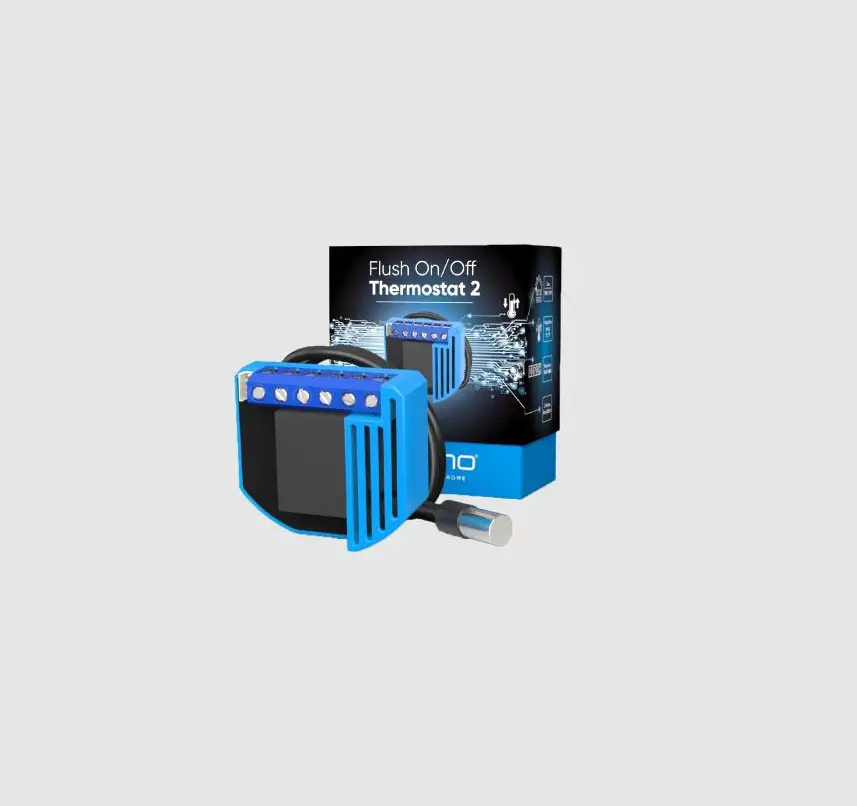
Qubino QUZMNHID3 Flush ON/OFF Thermostat
2 User Manual

The Flush On/Off Thermostat 2 is ideal for remotely controlling electric or water-based underfloor heating systems, electric water heaters, hot water pumps, electric radiators and similar. It measures power consumption and supports the connection of a digital temperature sensor, which is included in the package.
PACKAGE CONTENTS
Flush On/Off Thermostat 2 Device, Temperature sensor, Installation Manual
INSTALLATION
- To prevent electrical shock and/or equipment damage, disconnect electrical power at the main fuse or circuit breaker before installation and maintenance.
- Be aware that even if the circuit breaker is off, some voltage may remain in the wires — before proceeding with the installation, be sure no voltage is present in the wiring.
- Take extra precautions to avoid accidentally turning on the device during installation.
- Connect the device exactly according to the diagram.
- Place the antenna as far as possible from metal elements as they may cause signal interference.
- Do not shorten the antenna.
Danger of electrocution!
Installation of this device requires a great degree of skill and may be performed only by a licensed and qualified electrician. Please keep in mind that even when the device is turned off, voltage may still be present in the device’s terminals.
Note!
Do not connect the device to loads exceeding the recommended values. Connect the device exactly as shown in the provided diagrams. Improper wiring may be dangerous and result in equipment damage. Electrical installation must be protected by directly associated overcurrent protection fuse 10A, gag or Time lag T, rated breaking capacity 1500A (ESKA 522.727) must be used according to wiring diagram to achieve appropriate overload protection of the device. The fuse must be installed in fuse holder type: Adele contact 503Si/1 DS according to the standard IEC60669-2-1.
Z-WAVE INCLUSION
SMARTSTART INCLUSION
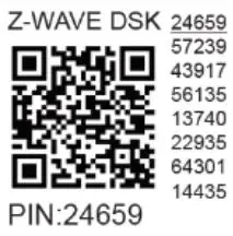
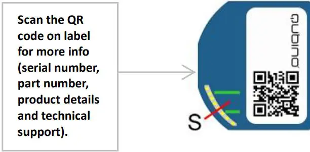
- Scan QR code on device label and add S2 DSK to Provisioning List in gateway (hub)
- Connect the device to the power supply (with the temperature sensor already connected)
- Inclusion will be initiated automatically within few seconds of connection to the power supply and the device will automatically enrol in your network (when the device is excluded and connected to the power supply it automatically enters the LEARN MODE state).
MANUAL INCLUSION
- Enable add/remove mode on your Z-Wave gateway (hub)
- Connect the device to the power supply (with the temperature sensor already connected*)
- Toggle the switch connected to the I1 terminal 3 times within 3 seconds (1 click per second). The device has to get On/Off signal 3 times, meaning 3 times push of the push button or with the normal button 3 times On/Off .
- Inclusion with the switch connected to I1 terminal is not limited by time
OR
If the device is powered by 24 V SELV supply, press and hold the S (Service) button between 3 and 6 seconds (this procedure puts the device in LEARN MODE). 3. A new on/off device will appear on your dashboard
4. Exclusion with the switch connected to I1 terminal is not limited by time
*Make sure the device is excluded from your network before connecting the temperature sensor. Switch off the power supply, connect the temperature sensor, and re-include the device to your network.
Note: In case of S2 Security inclusion a dialog will appear prompting you to enter the corresponding PIN number (5 underlined digits) that are written on the module label and the label inserted in the packaging (check the example picture). IMPORTANT: The PIN code must not be lost
Z-WAVE EXCLUSION/RESET
Z-WAVE EXCLUSION
- Connect the device to the power supply
- Make sure the device is within direct range of your Z-Wave gateway (hub) or use a hand-held Z-Wave remote to perform exclusion
- Enable exclusion mode on your Z-Wave gateway (hub)
- Toggle the switch connected to the I1 terminal 3 times within 3 seconds
OR
If the device is powered by 24 V SELV supply, press and hold the S (Service) button between 3 and 6 seconds - The device will be excluded from your network but any custom configuration parameters will not be erased.
NOTE1: LEARN MODE state allows the device to receive network information from the controller. NOTE2: After device is excluded you should wait 30seconds before performing re-inclusion.
FACTORY RESET
- Connect the device to the power supply
- Within the first minute the device is connected to the power supply, toggle the switch connected to the I1 terminal 5 times within 5 seconds
OR
If the device is powered by 24 V SELV supply, press and hold the S (Service) button for more than 6 seconds
By resetting the device, all custom parameters previously set on the device will return to their default values, and a node ID will be deleted. Use this reset procedure only when the gateway (hub) is missing or otherwise inoperable.
NOTE: See extended manual for custom settings and parameters available for this device.
IMPORTANT DISCLAIMER
Z-Wave wireless communication is not always 100% reliable. This device should not be used in situations in which life and/or valuables are solely dependent on its functioning. If the device is not recognized by your gateway (hub) or shows up incorrectly, you may need to change the device type manually and make sure your gateway (hub) supports Z-Wave Plus devices. Contact us for help before returning the product: http://qubino.com/support/#email
WARNING
Do not dispose of electrical appliances as unsorted municipal waste, use separate collection facilities. Contact your local government for information regarding the collection systems available. If electrical appliances are disposed of in landfills or dumps, hazardous substances can leak into the groundwater and get into the food chain, damaging your health and well-being. When replacing old appliances with new ones, the retailer is legally obligated to take back your old appliance for disposal free of charge.
ELECTRICAL DIAGRAM (110 – 240 VAC, 24 VDC)
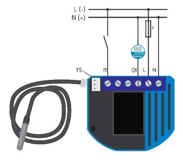
Notes for diagram:
N Neutral lead (+VDC)
L Live lead (-VDC)
Q↑ Output for electrical device
I1 Input for switch / push button
TS Temperature sensor terminal
Wagon 221-413 splicing connectors for L and N connections must be used only when connected to 240VAC.
WARNING:
The S (Service) button must NOT be used when the device is connected to a 110-240V power supply. The durability of the device depends on the applied load. For resistive loads (light bulbs, etc.) and 10A current consumption of an electrical device, the product’s lifespan exceeds 100,000 toggles.
TECHNICAL SPECIFICATIONS
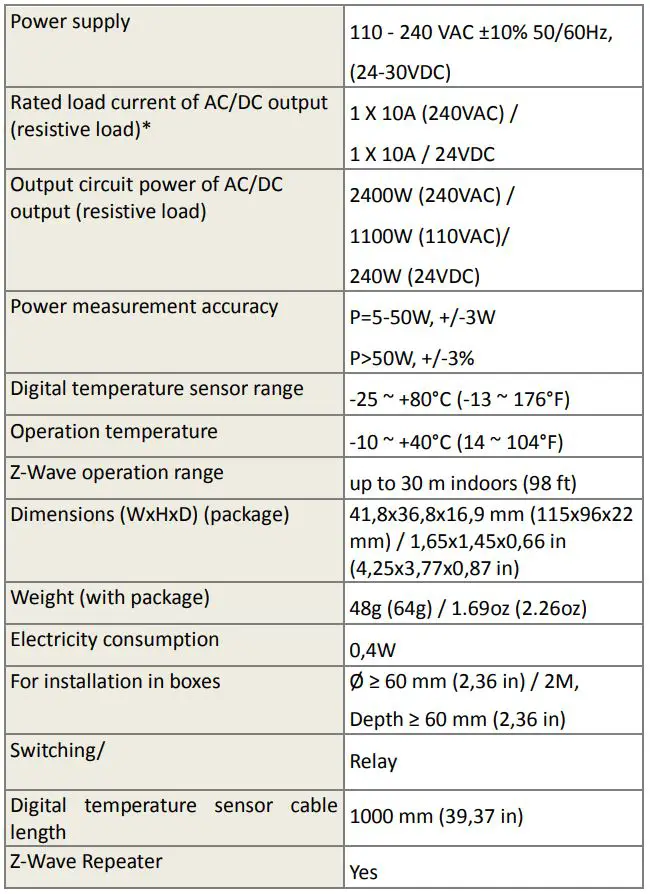
*In case of loads other than resistive loads, please pay attention to the value of cos . If necessary, connect loads less powerful than what they’re rated for this applies to all motor loads. Max current for cos =0,4 is 3A at 250VAC, 3A at 24VDC L/R=7ms.
ORDERING CODE AND FREQUENCIES
ZMNKIXY X, Y values define product version per region. Please check online extended manual or catalogue for the right version.
Get a real Qubino Z-Wave bible! How-to install, use cases, illustrations and more. Scan the QR code/follow the link below:
https://qubino.com/products/flush-on-offthermostat-2/
![]()
FCC compliance statement (applies only in the US):
This device complies with part 15 of the FCC Rules. Operation is subject to the following two conditions: (1) This device may not cause harmful interference, and (2) this device must accept any interference received, including interference that may cause undesired operation NOTE: This equipment has been tested and found to comply with the limits for a Class B digital device, pursuant to part 15 of the FCC Rules. These limits are designed to provide reasonable protection against harmful interference in a residential installation. This equipment generates, uses and can radiate radio frequency energy and, if not in-stalled and used in accordance with the instructions, may cause harmful interference to radio communications. However, there is no guarantee that interference will not occur in a particular installation. If this equipment does cause harmful interference to radio or television reception, which can be determined by turning the equipment off and on, the user is encouraged to try to correct the interference by one or more of the following measures: –Reorient or relocate the receiving antenna. –Increase the separation between the equipment and receiver. –Connect the equipment into an outlet on a circuit different from that to which the receiver is connected. –Consult the dealer or an experienced radio/ TV technician for help. This user manual is subject to change and improvement without prior notice.
Goap d.o.o. Nova Gorica
Ulica Klementa Juga 007, 5250 Solkan, Slovenia
E-mail: [email protected] ; Tel: +386 5 335 95 00
Web: www.qubino.com; Date: 12.07.2019; V 2.0


