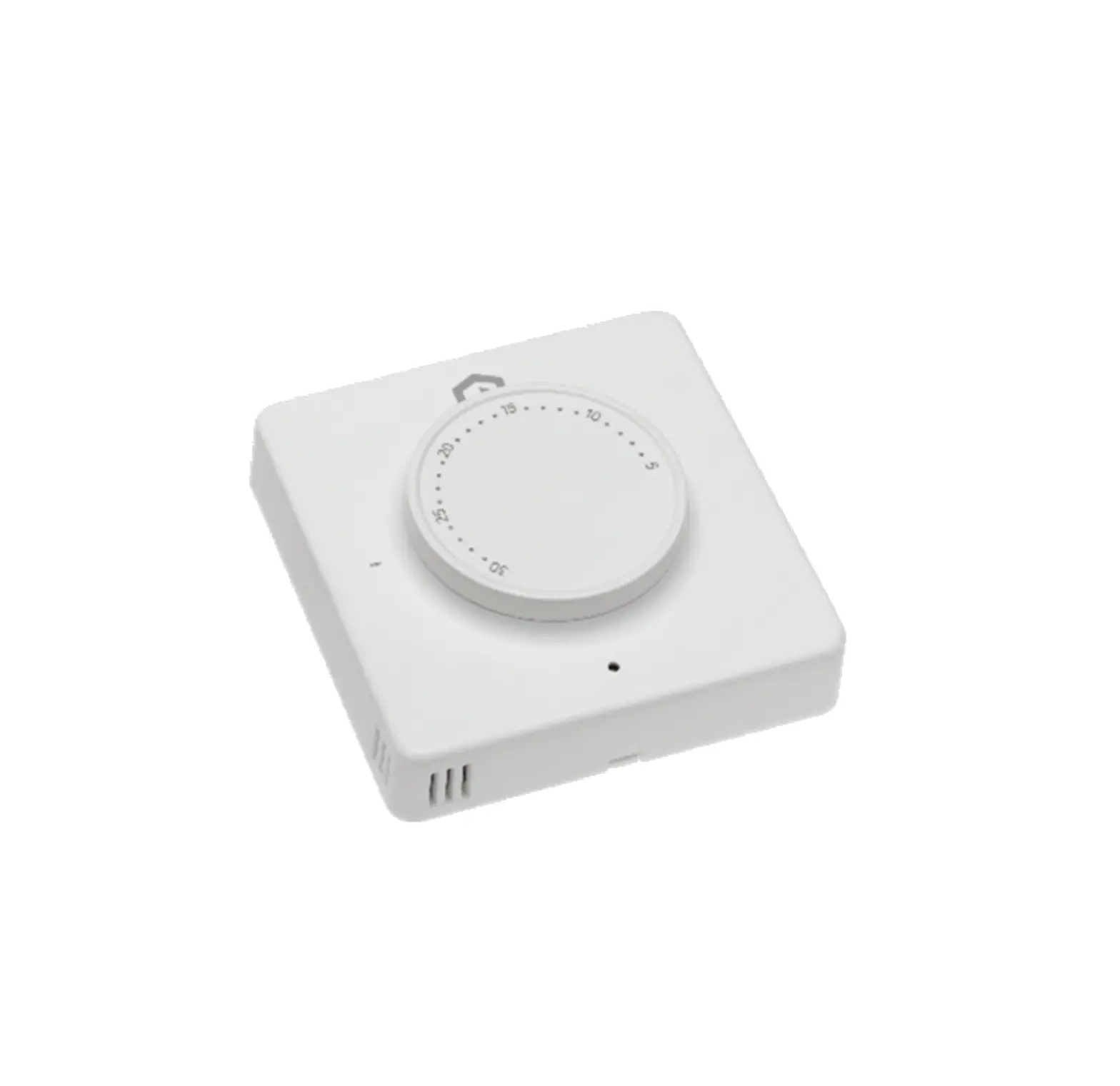
MYSON Unisenza Dial Thermostat

SAFETY WARNING
During installation and operation of the device, it is necessary to comply with the following instructions:
- The device must be installed by a skilled person, in strict compliance with the connection diagrams.
- Do not power on or connect the device if any part of it is damaged.
- After installation, inaccessibility to the connection terminals without appropriate tools must be granted.
- The device must be installed and activated in compliance with current electric systems standards.
- Before accessing the connection terminals, verify that the leads are not live.
TECHNICAL SPECIFICATIONS
- Purpose of control: electronic thermostat;
- Construction of control and whether the control is electronic (see above example);
- Setting range: +5/+30 °C;
- Supply voltage: 230 V~ ±10 % – 50/60 Hz;
- Power consumption: 3 W;
- Capacity of the contacts: 2 (1) A 230 V~ (not voltage free);
- Type of automatic action: 1;
- Construction: Class II;
- Ingress protection: IP 30;
- Operating temperature: 0 °C…40 °C;
- Operating humidity: 20 %…90 % rH non condensing;
- Storage temperature: -20 °C…60 °C;
- Shock load voltage: 2,5 KV;
- Temperature for Ball Pressure Test: 90° C;
- Pollution degree: 2 (normal).
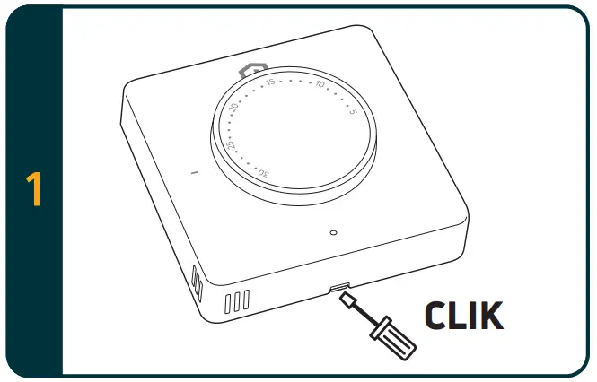
INSTALLATION AND ELECTRICAL CONNECTION
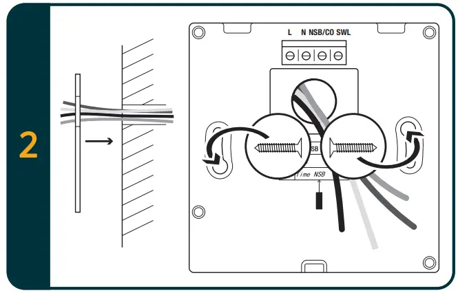
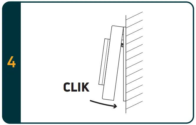
Wall fixing
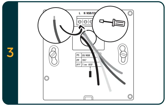
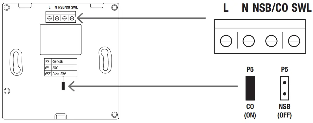
Wiring diagram
Thermostat terminals description
| Terminals | 230 Vac version | 24 Vac version |
| 1. L | Live input 230 Vac | Live input 24 Vac |
| 2. N | Neutral input 230 Vac | Neutral input 24 Vac |
| 3. NSB with jumper (P5) OFF | Night set back input (Live 230 Vac input: reduced mode) | Night set back input (Live 24 Vac input: reduced mode) |
| 3. CO with jumper (P5) ON | Heating and Cooling input (Live 230 Vac input: cooling) | Heating and Cooling input (Live 24 Vac input: cooling) |
| 4. SWL | Switch output (Live 230 Vac during request) | Switch output (Live 24 Vac during request) |
Type of wirings
| Functions | Jumper | Wiring diagram |
| Heating and cooling function | 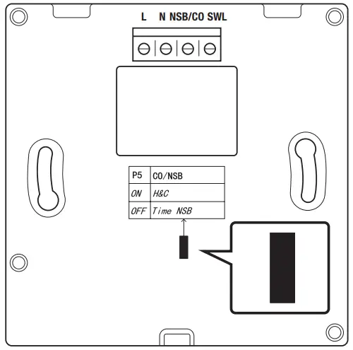 Jumper ON | No Live on CO/NSB terminal: Heating with temperature setpoint setting by the knob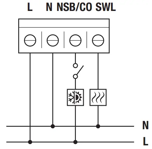 |
Live on CO/NSB terminal: Cooling with temperature setpoint setting by the knob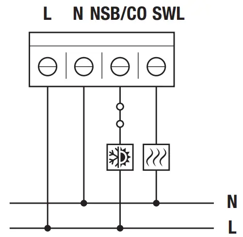 | ||
| NSB function | 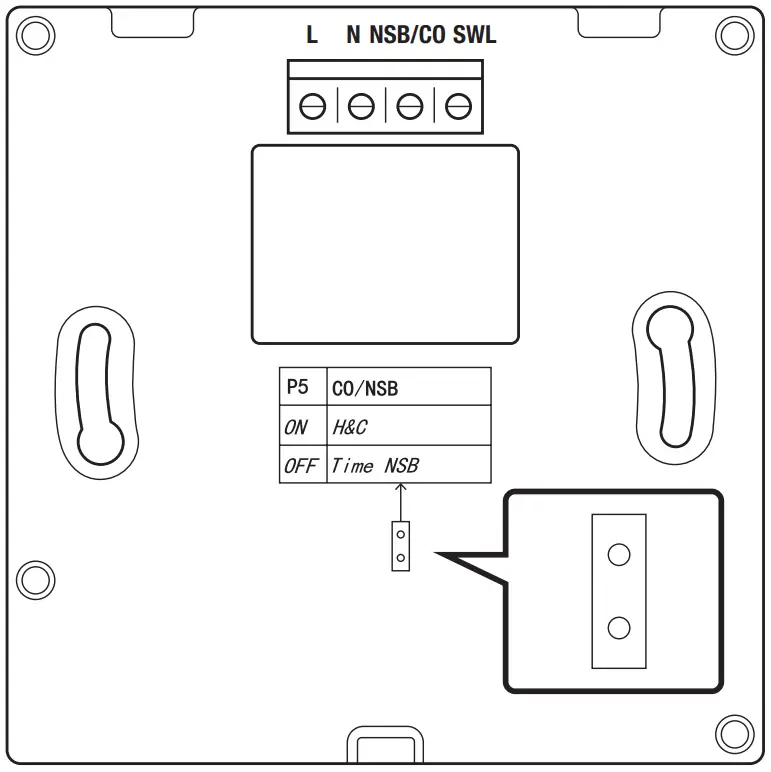 Jumper OFF | No Live on CO/NSB terminal: Heating with temperature setpoint setting by the knob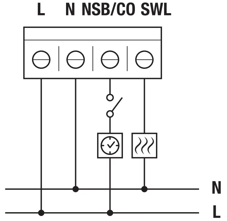 |
Live on CO/NSB terminal: Heating with 2° C less than the set temperature setpoint by the knob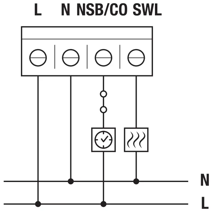 |
Connection to the Wiring Centre
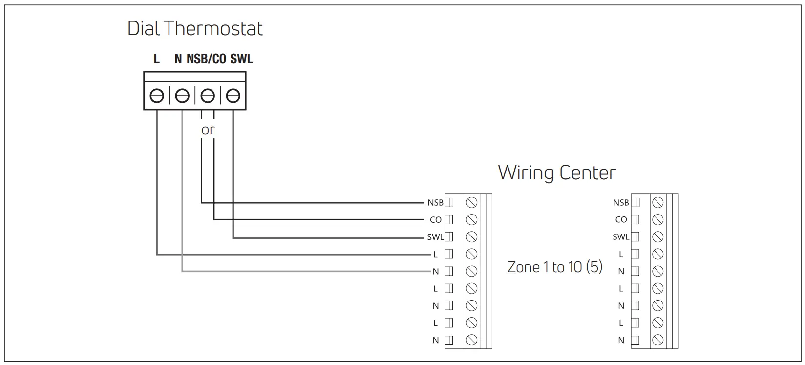
Note:
– CO connection is optional. It’s needed to use change over function. (Further explanation in Wiring center manual).
– NSB connection is optional. It’s needed to use night setback function. (Further explanation in Wiring center manual).
USER GUIDE
Description
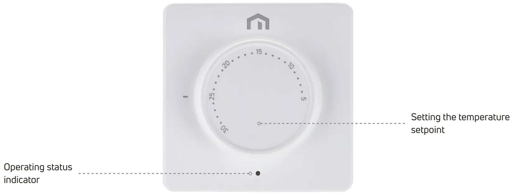
Setting the temperature setpoint
| Decrease temperature | Increase temperature |
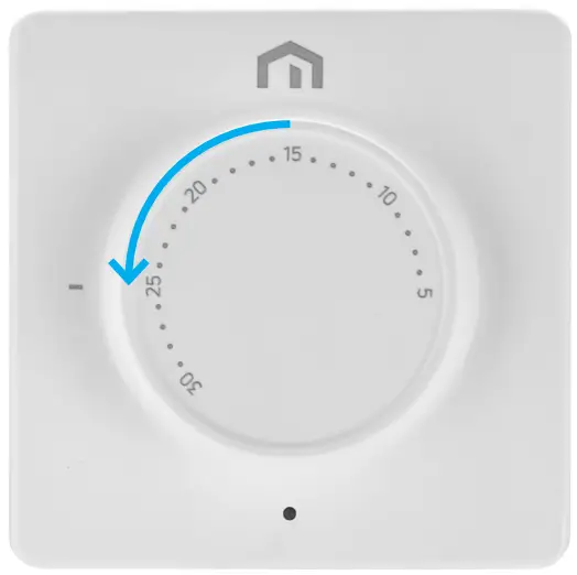 | 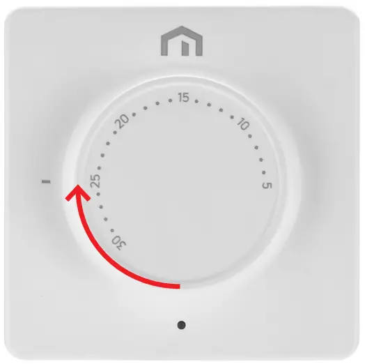 |
Operating status indicator
| Red led On – Heating | Blue led On – Cooling |
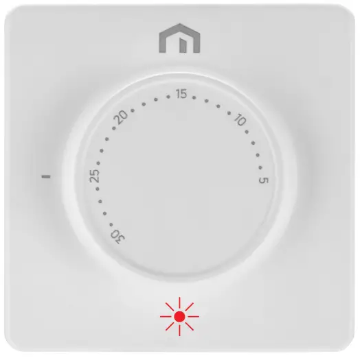 | 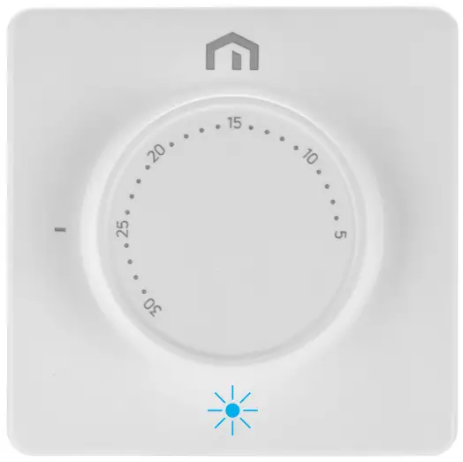 |
WEEE DIRECTIVE APPLICATION – DIRECTIVE 2012/19 / EU
![]() The crossed-out wheeled bin symbol indicates that within the European Union all electrical and electronic products at the end of their useful life must be collected separately from other waste.
The crossed-out wheeled bin symbol indicates that within the European Union all electrical and electronic products at the end of their useful life must be collected separately from other waste.
Do not dispose of this equipment in unsorted municipal waste. Assign the equipment to the appropriate collection centers for electrical and electronic waste or return it to the retailer when purchasing a new equivalent type of equipment.
Appropriate separate collection of equipment to start the subsequent recycling, treatment and environmentally compatible disposal helps to avoid possible negative effects on the environment and health due to the presence of hazardous substances in electrical and electronic equipment and resulting from an incorrect disposal or improper use of the same equipment or parts thereof, the separate collection also favors the recycling of the materials of which the equipment is composed.
The current legislation provides for sanctions in case of illegal disposal of the product.
Customer Support
A PURMO GROUP BRAND
Bulevardi 46
P.O. Box 115
FI-00121 Helsinki
Finland
www.purmogroup.com
Every care has been taken in the creation of this document. No part of this document may be reproduced without the express written consent of Purmo Group. Purmo Group accepts no responsibility for any inaccuracies or consequences arising from the use or misuse of the information contained herein.


