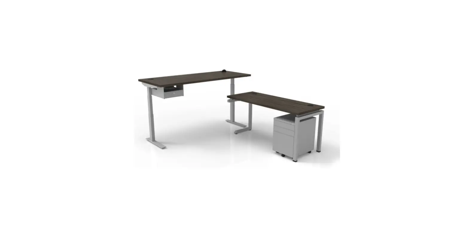
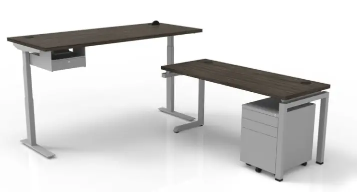
CLEAR DESIGN BHA2GSA Boost Height-Adjustable Workstation 
WORKSTATION
OVERVIEW
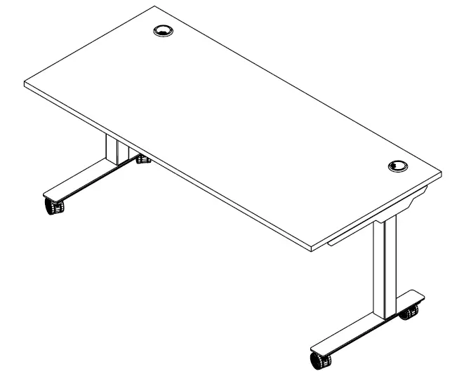
BOOST Height-Adjustable Workstation
All parts listed are for a single workstation; additional parts will be needed for additional workstations.
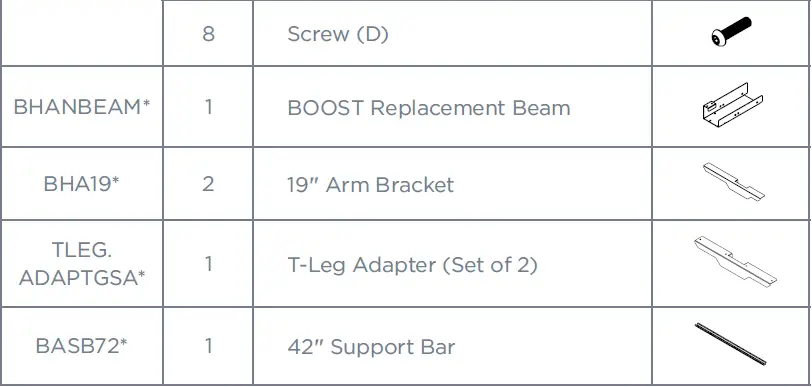
PARTS LIST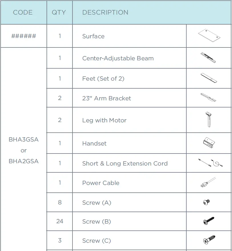
DETERMINE SURFACE SIZE FOR INSTALLATION
Use the chart below to identify which arm brackets will be used with surface size, and if surface will need replacement beam (BHANBEAM).
Note: Reference STEP 4 after completing STEP 2 and 3.
| Surface Depth | Surface Width | Including Surface Dividers? | Arm Bracket Type | BHANBEAM | Reference Step 4 |
| 24″ | 36″-47″ | No | Default | Yes | A |
| 24″ | 36″-47″ | Yes | BHA19 | Yes | B |
| 24″ | 48″ | No | Default | No | C |
| 24″ | 48″ | Yes | BHA19 | No | D |
| 24″ | 54″-72″ | No | Default | No | E |
| 24″ | 54″-72″ | Yes | Default | No | F |
| 30″ | 36″-47″ | Yes/ No | Default | Yes |
G |
| 30″ | 54″-72″ | Yes/ No | Default | No |
ASSEMBLE WORKSTATION FRAME
Attach legs with motor and arm brackets to the center beam using screws (A).
Note: Replace the default arm brackets if workstation requires BHA19 or T-brackets. Surface width 36″-47″ will need to replace the beam, without the control box, with BOOST replacement beam (BHANABEAM).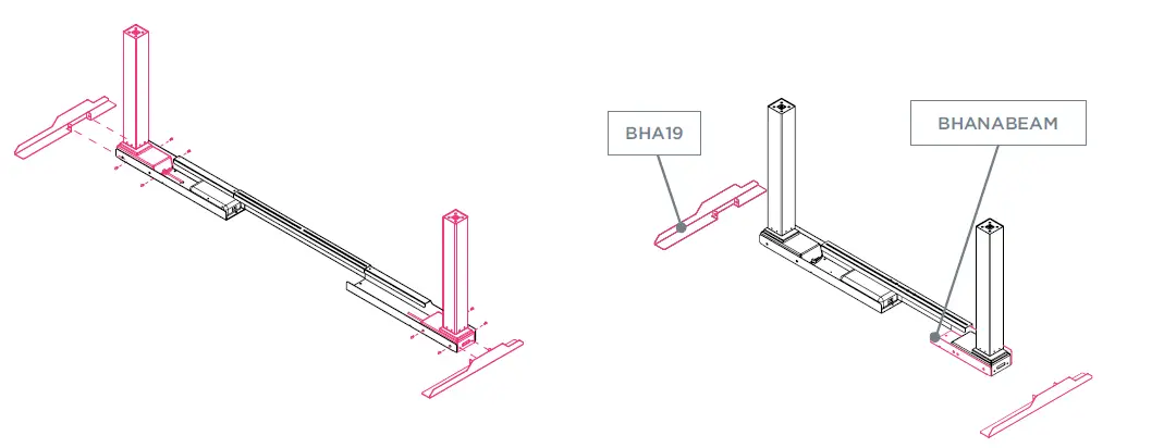
PLACE FRAME ON THE SURFACE
Loosen existing locking screws on the adjustable beam to extend beam to fit table size. Run cord through cutout from the adjustable beam and secure the handset to control box. Attach the short extension cord to the motor closest to control box and attach the longer extension cord on the opposite end.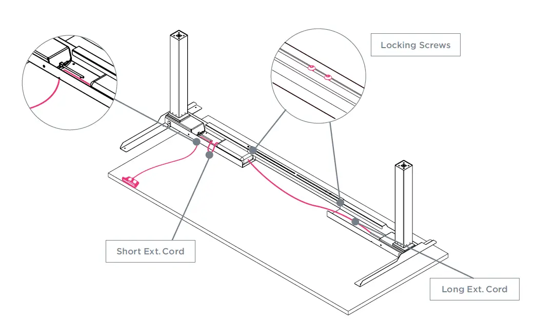
ADJUST FRAME ON SURFACE
Note: Based on STEP 1 surface size chart, reference one of the following workstation diagrams to secure frame.
(A) 24″D x 36″–47″W Surfaces without Side Dividers
Extend the frame equal to the surface width. Center arm brackets in reference to surface depth. Secure frame to surface using wood screws (B) and secure handset using wood screws (C).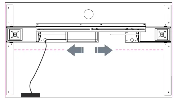
(B) 24″D x 36″–47″W Surfaces with Side Dividers
If using side dividers, frame will include arm brackets BHA19. Extend the frame equal to the surface width. Center arm brackets in reference to surface depth. Secure frame to surface using wood screws (B) and secure handset
using wood screws (C).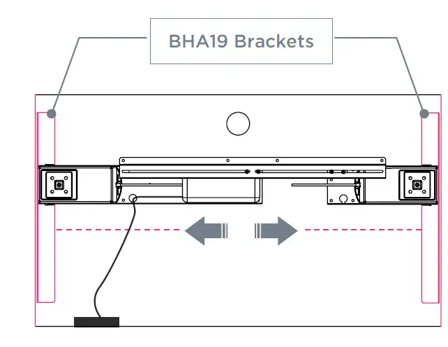
(C) 24″D x 48″W and Smaller Surfaces without Side Dividers
Extend the frame equal to the surface width. Center arm brackets in reference to surface depth. Secure frame to surface using wood screws (B) and secure handset using wood screws (C).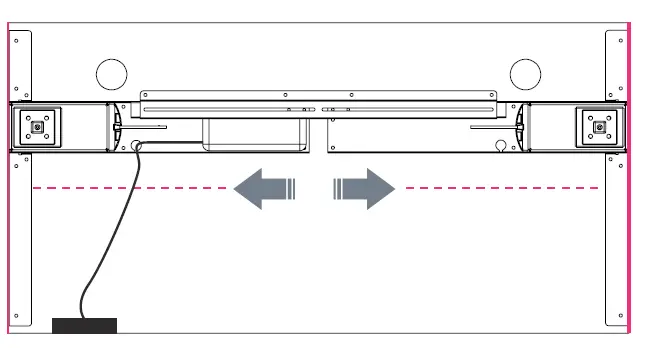
(D) 24″D x 48″W and Smaller Surfaces with Side Dividers
If using side dividers, frame will include arm brackets BHA19. Extend the frame equal to the surface width. Center arm brackets in reference to surface depth. Secure frame to surface using wood screws (B) and secure handset
using wood screws (C).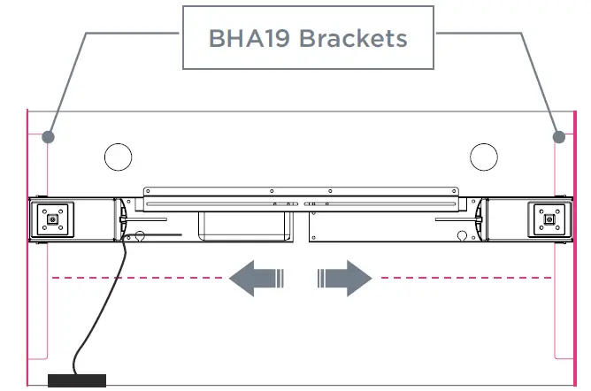
(E) 24″D x 54″–72″W Surfaces without Dividers
Extend the frame equal to the surface width. Center arm brackets in reference to surface depth. Secure frame to surface using wood screws (B) and secure handset using wood screws (C).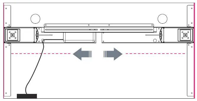
(F) 24″D x 54″–72″W Surfaces with Side Dividers
If using side dividers, inset the frame 2” from each end. Center arm brackets to surface depth. Secure frame to surface using wood screws (B) and secure handset using wood screws (C).
Note: If using side dividers AND a facing divider with BSBHL, replace the arm brackets with BHA19.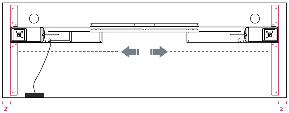
(G) 30″ Deep Surfaces
Extend the frame equal to the surface width. Center arm brackets to surface depth. Secure frame to surface using wood screws (B) and secure handset using wood screws (C).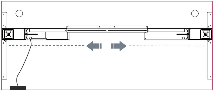
SECURE POWER CORD & INSTALL FEET
Secure power cord to the control box. Secure locking screws on the adjustable beam and install the feet using screws (D) for each leg. If workstation is complete, flip over. Reference handset guide for initialization and operation functions.
Note: Use T-feet if using T-arm brackets.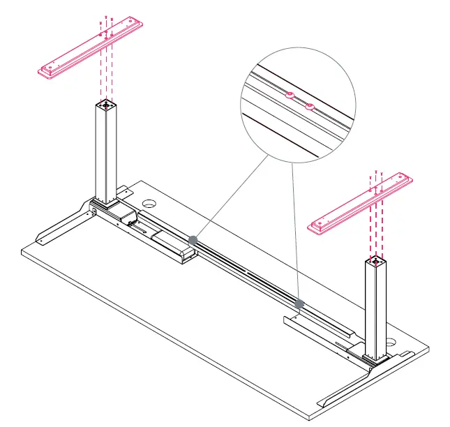
CASTERS
OVERVIEW
BOOST Height-Adjustable Workstation
All parts listed are for a set of 4 casters; additional parts will be needed for additional casters.
PARTS LIST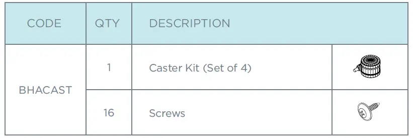
REMOVE GLIDES FROM FEET
Unscrew all four glides from feet and disregard.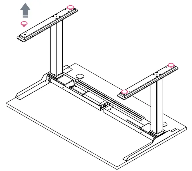
ATTACH CASTERS TO FEET
The workstation’s feet have pre-drilled holes for the caster plate. Attach casters using self-tapping metal screws.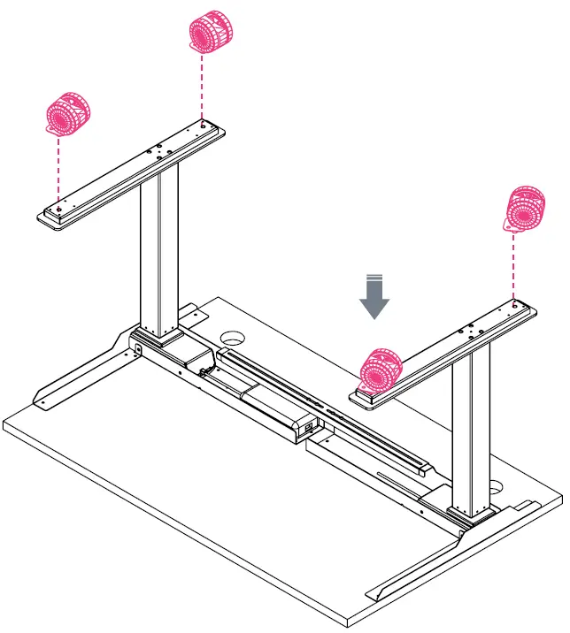
MODESTY PANEL
OVERVIEW
BOOST Height-Adjustable Workstation
All parts listed are for a single modesty panel; additional parts will be needed for additional modesty panels.
PARTS LIST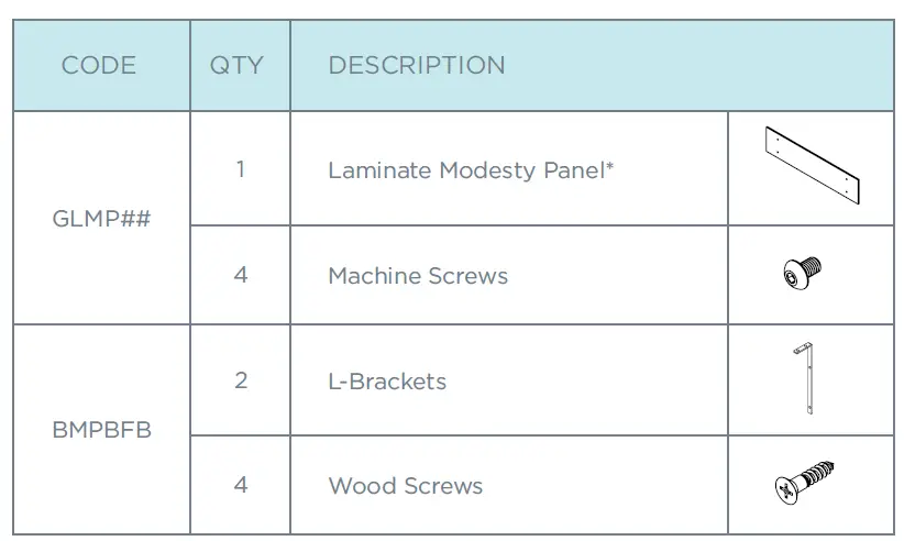
*For Steel Modesty Panel: components may vary, but the process is similar.
SECURE BRACKETS TO MODESTY PANEL
Connect the BMPBFB bracket to the modesty panel using screws. Secure tightly.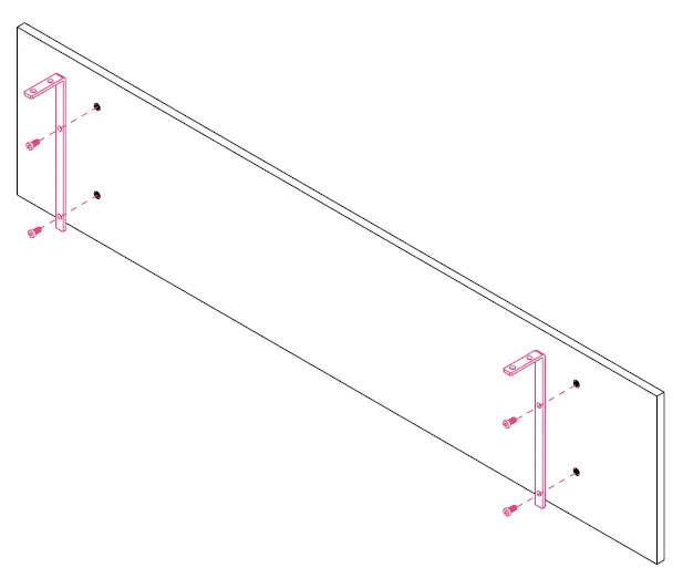
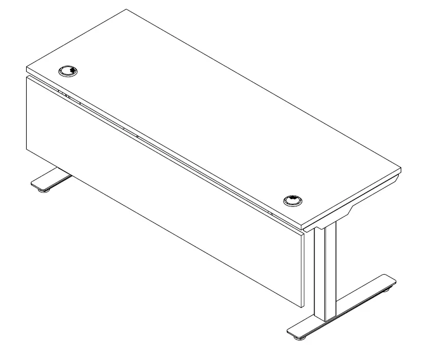
ATTACH MODESTY PANEL TO SURFACE
Attach modesty panel to surface using wood screws provided with brackets. Panel will be center aligned and flushed with back of surface.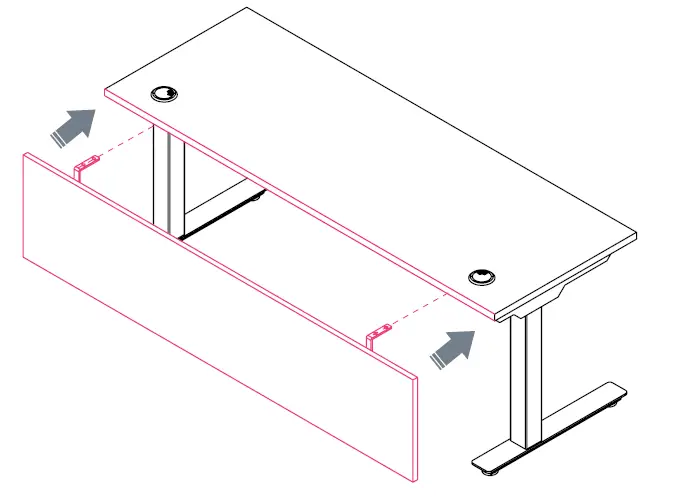
SLIM PEDESTAL
OVERVIEW
BOOST Height-Adjustable Workstation
All parts listed are for a single slim pedestal; additional parts will be needed for additional slim pedestals.
PARTS LIST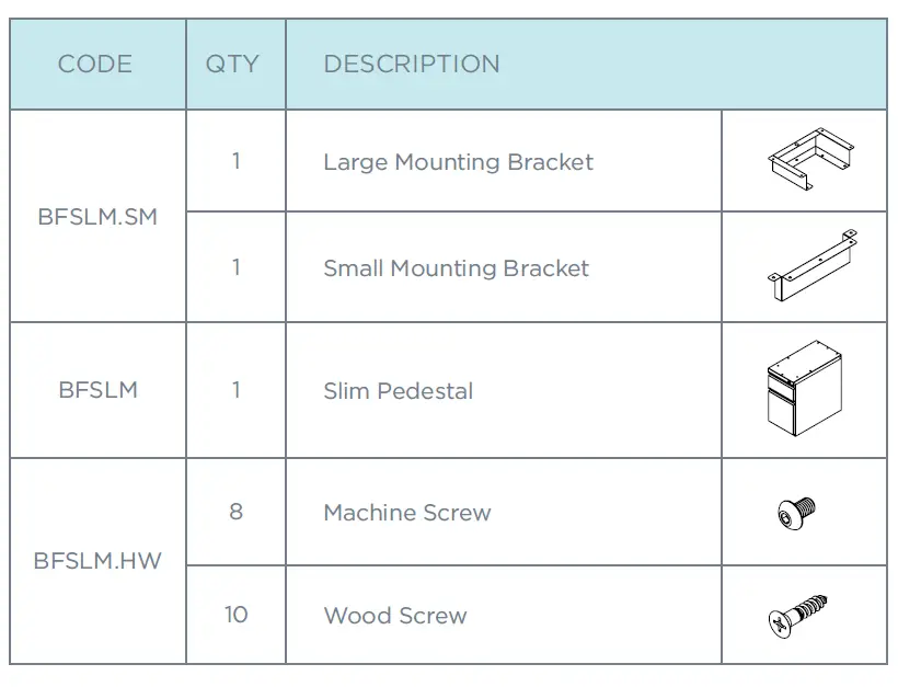
SECURE BRACKETS TO SLIM PEDESTAL
Align large mounting bracket to front of pedestal and align small mounting bracket to back. Secure both brackets using provided screws.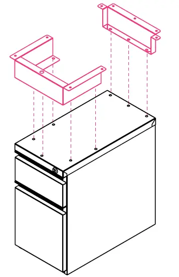
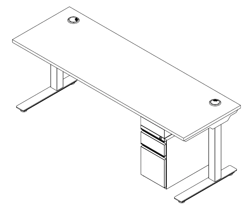
ATTACH SLIM PEDESTAL TO SURFACE
Secure pedestal to surface using wood screws. The pedestal brackets will connect on either side of the center beam.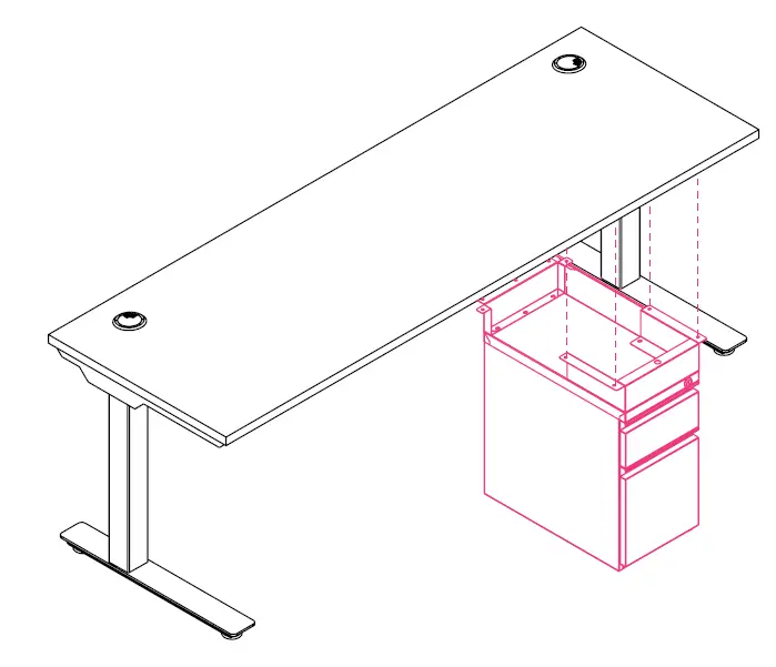
CABLE TRAY
OVERVIEW
BOOST Height-Adjustable Workstation
All parts listed are for a single cable tray; additional parts will be needed for additional cable trays.
PARTS LIST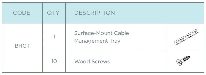
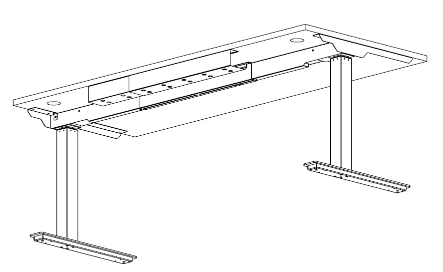
EXTEND CABLE TRAY TO DESIRED LENGTH
Extension range: 25″–45″.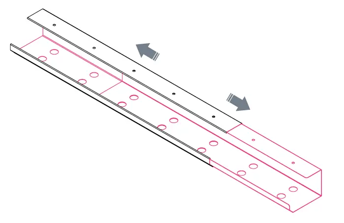
ATTACH CABLE TRAY TO SURFACE
Attach cable tray using wood screws. 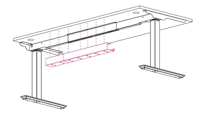
1-866-304-7197 | [email protected] | mycleardesign.com
© 2022 Clear Design | Version 22.1.0


