I-SYST BLUEIO832-MINI Nano System-on-Module
Abstract
We provide a brief overview of the features of BlueIO832-Mini and its specifications. Next, we present the steps of setting up BlueIO832-Mini as a serial interface bridge between BlueIOTerm mobile application and an arbitrary physical device. Finally, we introduce the users the resources for self-developing their own firmware on the BlueIO832-Mini
Revision History
Table 1. Document Revision
| Revision no. | Description | Data | Prepared by | Approved by |
| 1.0 | 2nd draft | Aug 15, 2022 | Duy Thinh Tran |
Overview to BlueIO832-Mini
Key features of BlueIO832-Mini and the BlueIO ecosystem
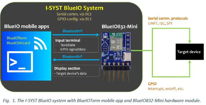
The BlueIO832-Mini and the free BlueIO mobile apps suite constitute to the I-SYST BlueIO ecosystem. This versatile Internet-of-Thing (IoT) framework enables users, from their mobile device such as a smartphone, to remotely communicate with an arbitrary physical device – referred to as a target device in this document (Fig. 1). BlueIO832-Mini and BlueIO mobile app are considered as a data bridge and a data terminal, respectively. After connecting to the target device via a desired serial interface, BlueIO832-Mini streams the data on that physical interface to the BlueIO mobile app over Bluetooth® 5 protocol. BlueIO832-Mini provides four built-in app-configurable features of data communications with a target device:
- [1] Serial interface bridge: (i) Connect BlueIO832-Mini to a serial interface (UART, I2C, or SPI) of a target device. (ii) Pair BlueIO832-Mini with BlueIO mobile app on a mobile device. (iii) Configure the serial interface setting in BlueIO mobile app. (iv) Use BlueIO mobile app to remotely send and receive data on this interface.
- [2] GPIO functions: (i) Use BlueIO mobile app to configure pins of BlueIO832-Mini as GPIO for sending/receiving signal to/from a target device. (ii) Pair BlueIO832-Mini with BlueIO mobile app on a mobile device. (iii) Use BlueIO mobile app to send/receive signals(s) to/from the GPIO pin(s).
- [3] Analog-to-Digital Converter (ADC): (i) Use BlueIO832-Mini to convert (up to 3) analog signals to digital signals. (ii) Pair BlueIO832-Mini with BlueIO mobile app on a mobile device. (iii) Use BlueIO mobile app for monitoring the converted digital signals.1
- [4] NFC tag: BlueIO832-Mini can be used as an NFC tag once a Nordic®-compatible NFC antenna is plugged into the NFC connector. 2
Besides that, BlueIO832-Mini can be used as an IoT embedded development kit for developing the user’s own firmware by using Nordic® SDK. However, we recommend the user to use our open-source library IOsonata, which is built upon the Nordic® SDK, for faster and easier developing firmware on BlueIO832-Mini and any other Nordic® nRF52x SoC-based embedded system. Here are useful references for the IOsonata SDK and the guides on firmware development with IOsonata:
- IOsonata is available on this Github link.
- The steps of developing firmware with IOsonata SDK are available on this blogpost.
- For debugging the firmware built upon IOsonata in Eclipse® IDE, please refer to this blogpost.
Note 1, 2: Feature [3] and [4] are not enabled in the current built-in firmware version.
Hardware Specification and Pin Layout
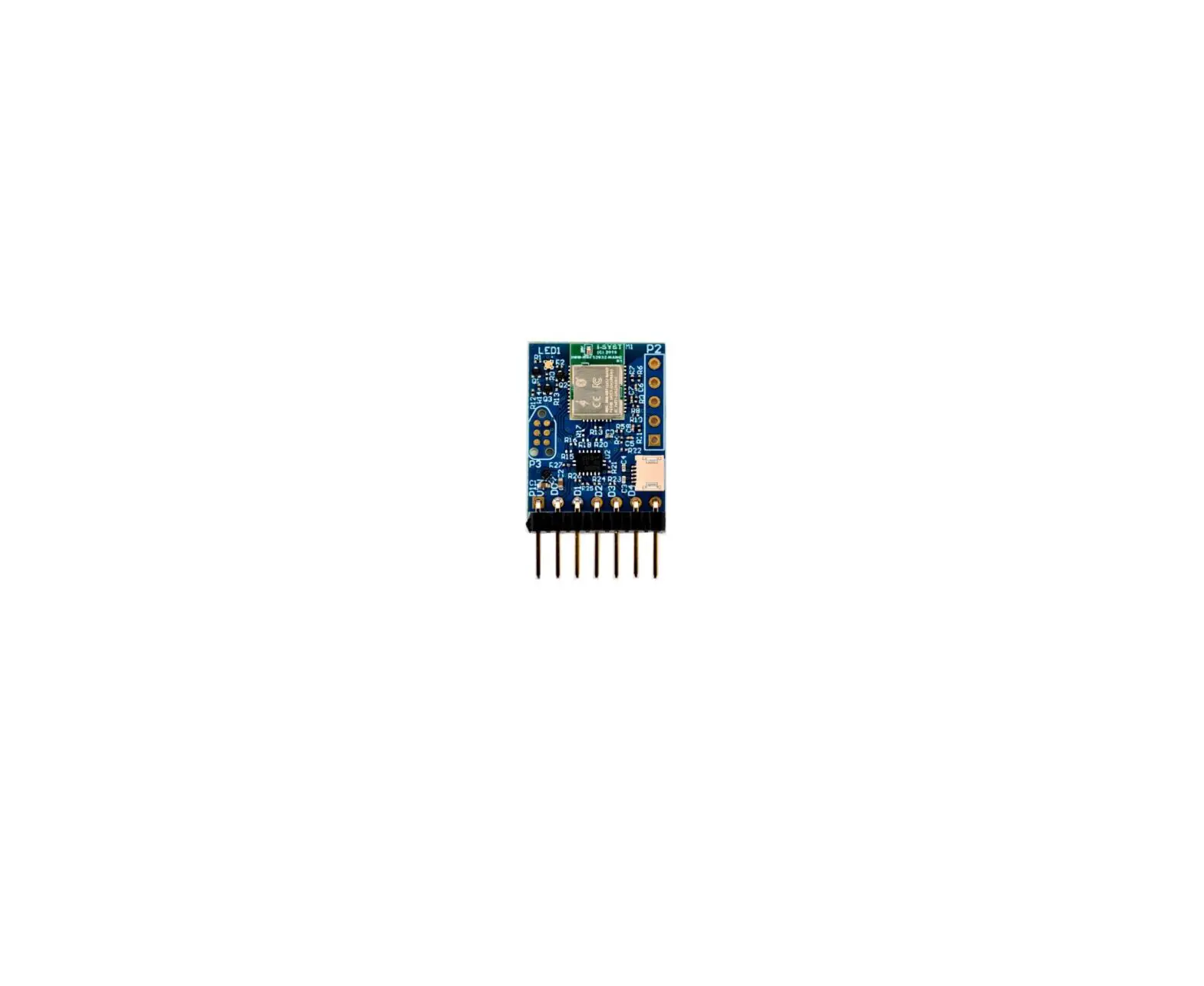
The heart of BlueIO832-Mini is the I-SYST BLYST Nano System-on-Module (SoM) built upon the Nordic® nRF52832 System on Chip (SoC), which is an ultra-low power 2.4 GHz wireless SoC. This Soc is equipped with 64 MHz ARM® Cortex®-M4F processor, 64 KB RAM, 512 KB flash memory. The SoC provides several serial interfaces such as UART, I2C, SPI and especially the Bluetooth® 5 low-energy mode. For more details of the I-SYST BLYST Nano, please refer to this webpage. The detail specifications of Nordic® nRF52832 SoC can be downloaded from the Nordic’s website.
BlueIO832-Mini supports:
- Bluetooth® 5 low energy (BLE) mode
- A wide range of supply voltage ranging from 1.8 to 5.5 volts [VIN]
- Internal level shifter supporting GPIO voltage matching the supply voltage
- 4 x pins [D0 – D3] which can be configured (via BlueIOWizard mobile app) as
- 1 x UART
- Baud rates up to 1000000 (1M baud)
- Hardware flow control
- Bit parity
- 1 x I2C master
- 100 kbps, 250 kbps, 400 kbps
- 1 x SPI master
- 125 kbps, 250 kbps, 500 kbps
- 1 Mbps, 2 Mbps, 4 Mbps, 8 Mbps
- 4 x GPIO with configurable parameters:
- Direction
- Drive strength
- Pull-up/pull-down resistors enabling
- Pin sensing
- 1 x UART
- 3 x Configurable ADC channels [ADC0 – ADC2]
- Max input voltage 1.8V
- 12-bit resolution
- 1 differential mode
- 3 independent channels
- NFC antenna socket
- Works with any Nordic®-compatible NFC antenna
- JTAG
- A 6-pin JTAG connector on the front side
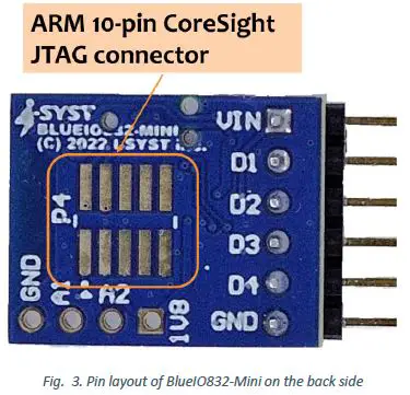
- An ARM® 10-pin CoreSight® JTAG connector on the back side
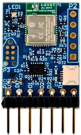
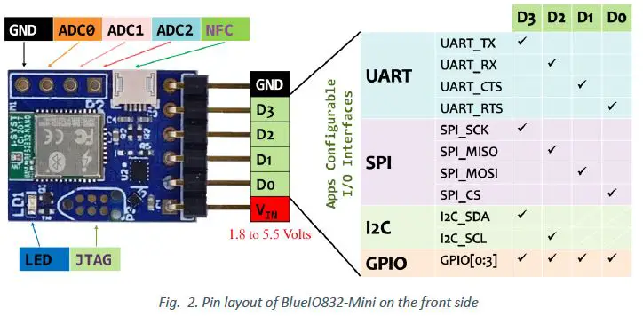
The pins and connectors layout of BlueIO832-Mini are shown in Figs. 2 and 3.
Depending on the use case and the specifications of the user’s target device, pins D1-D4 on BlueIO832-Mini can be configured for UART, SPI, I2C or GPIO by using BlueIOWizard mobile app. Please follow Figs.2 and 3 for the appropriate pin assignment.
BlueIO Mobile Apps
In our BlueIO ecosystem, we provide a set of multi-platforms BlueIO mobile apps tailored for different use cases of the BlueIO832-Mini. These mobile apps can be installed on smartphones, smartwatches, and tablets. Table I presents the use cases of each mobile app. Table II presents the availability of the mobile apps on different the platforms.
Table 2. BlueIO mobile apps and the use cases
| App Name | Use Cases | Pin configurable | ||||
| UART | SPI | I2C | GPIO | ADC | ||
| BlueIOTerm | No (*) | |||||
| BlueIOSpi | No | |||||
| BlueIOI2c | No | |||||
| BlueIOAdc | No | |||||
| BlueIOWizard | Yes – App configurable | |||||
(*): The pins are pre-configured as in Fig. 2.
Table 3. BlueIO mobile apps and their support platforms
|
App Name | Smart Phone | Tablet | ||
| Apple® iOS | Android | Apple® ipadOS | Android | |
| BlueIOTerm | ||||
| BlueIOSpi | ||||
| BlueIOI2c | ||||
| BlueIOAdc | ||||
| BlueIOWizard | ||||
An Example of Using BlueIOTerm Mobile App with BlueIO832-Mini
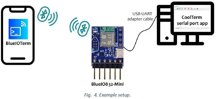
We illustrate an example using BlueIOTerm and BlueIO832-Mini for communicating with a target device over its UART interface. Here, the target device is a serial port app on a computer, which is then connected to BlueIO832-Mini via a USB-UART adapter. We demonstrate how to send text between the BlueIOTerm mobile app and the serial port app, typically CoolTerm, on a computer (Fig. 4).
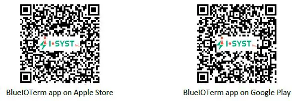
The BlueIOTerm mobile app can be downloaded using the QR codes here or the links in Reference section.
The CoolTerm serial port app can be downloaded here: https://freeware.the-meiers.org/
The steps are as follows:
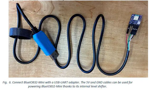
- Connect BlueIO832-Mini to the USB-UART adapter
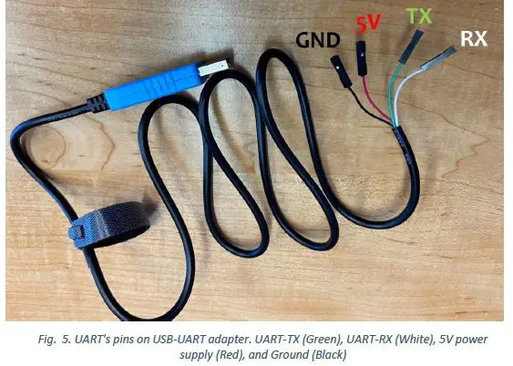
- Identify the pins of the UART port of the USB-UART adapter. Here Green cable is UART_TX and White cable is UART_RX. Red and Black cables are 5V and GND, respectively. Then plug the USB-UART adapter to the user’s computer.

- Based on the pin assignment table in Fig. 2, connect the BlueIO832-Mini [D1-D4] pins to the target device UART’s pins, as shown in Fig. 5.

- Identify the parameters of the target device’s UART interface: baud rate, flow control, and bit parity3. In this demo, the baud rate is 115200, no flow control, and no bit parity, 8-bit data frame.
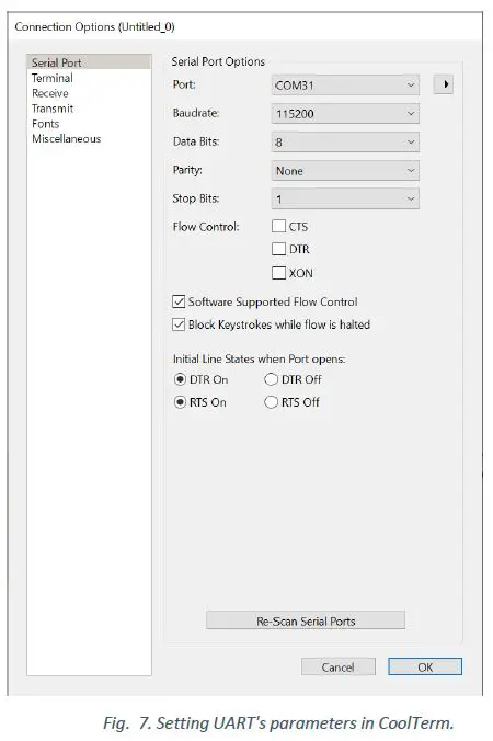
- Connect the USB-UART adapter to a computer. Install and open CoolTerm serial port app. In the CoolTerm Options menu → Serial Port Options, select the COM port number assigned for the USB-UART adapter, apply the UART parameters in step (iii) to Serial Port Options, and then click OK (Fig. 6).
Note 3: The data bits are always 8.
- Identify the pins of the UART port of the USB-UART adapter. Here Green cable is UART_TX and White cable is UART_RX. Red and Black cables are 5V and GND, respectively. Then plug the USB-UART adapter to the user’s computer.
- Pair BlueIO832-Mini with the BlueIOTerm on mobile device
- Install the BlueIOTerm on the user’s mobile device. The app can be found on Apple® AppStore and Google® Play app store.
- Configure UART’s setting on BlueIOTerm
- Turn on the Bluetooth® feature in the user’s mobile device.
- Open the BlueIOTerm mobile app.
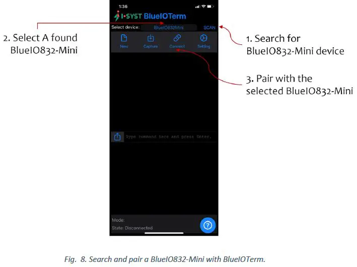
- Tap “SCAN” button to search for any BlueIO832-Mini existing arround. If the app found a BlueIO832-Mini, it displays “BlueIO832-Mini” onto the Select Device section (Fig. 7).


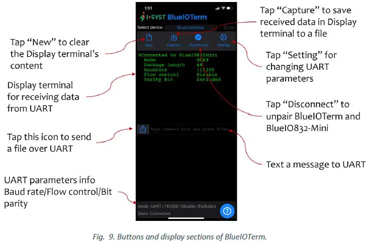
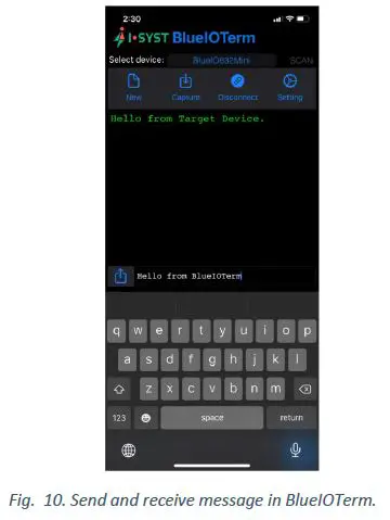
- Tap “Connect” to pair BlueIO832-Mini with the app. The display terminal on the app shows the current UART parameters used by BlueIO832-Mini (Figs. 8 and 9). Now, BlueIOTerm is ready for the user to send messages to and/or receiving messages from the UART interface connect with BlueIO832-Mini (Fig. 10).

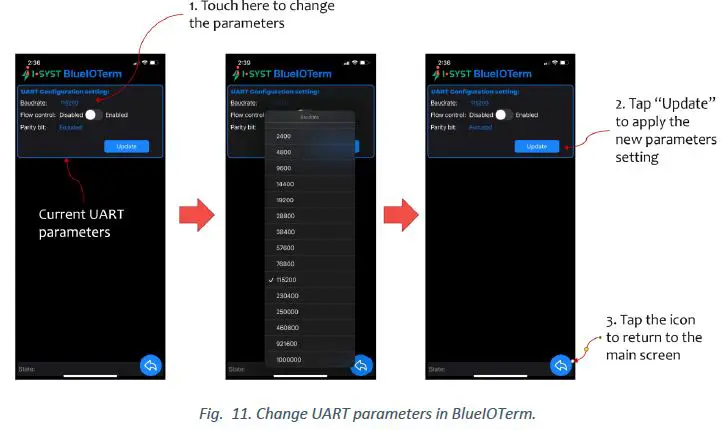
- To change the UART parameters, tap “Setting” to go to the UART configuration setting menu. The UART parameters shown in the menu are the current settings (Fig. 11).

User-Own Firmware Development on BlueIO832-Mini
BlueIO832-Mini can be used as an IoT embedded development kit for developing the user’s own firmware. We recommend the user to use our open-source library IOsonata for quickly developing the firmware. Here are references for the IOsonata SDK and the guides on firmware development with IOsonata:
- IOsonata is available on this Github link.
- The steps of developing firmware with IOsonata SDK are available on this blogpost.
- For debugging the firmware built upon IOsonata in Eclipse IDE, please refer to this blogpost.
References
- BlueIO832-Mini Product Page: https://www.i-syst.com/products/blueIO832

- BlueIO832-Mini User Guide:
https://www.i-syst.com/sites/default/files/2022-08/BlueIO832Mini_UserGuide.pdf - BlueIOTerm on Apple® AppStore
https://apps.apple.com/app/blueioterm/id1618808817?platform=iphone - BlueIOTerm on Google® Play
https://play.google.com/store/apps/details?id=com.i_syst.blueioterm - IOsonata Github
https://github.com/IOsonata/IOsonata - Developing firmware for Nordic® nRF52xxx SoC with IOsonata
https://www.i-syst.com/article/eclipse-ide-firmware-development-iosonata - Debugging firmware built upon IOsonata in Eclipse® IDE
https://www.i-syst.com/article/firmware-debugging-eclipse
Copyright 2022 I-SYST inc., all rights reserved.
[email protected]
References
 syst.com
 CoolTerm - Free download and software reviews - CNET Download
-
Roger Meier's Freeware
 GitHub - IOsonata/IOsonata: IOsonata multi-platform multi-architecture power & performance optimized software library for fast and easy IoT MCU firmware development. Object Oriented design, no board package to define, just pure plug & play any boards
-
Nordic Semiconductor Infocenter
-
Eclipse IDE in firmware development with IOsonata | I-SYST's Site
-
Firmware debugging with Eclipse | I-SYST's Site
-
BlueIO832-Mini | I-SYST's Site
-
IMM-NRF52832-NANO (BLYST Nano) | I-SYST's Site


