hoymiles HMS-800-2T Single Phase Microinverter
About Microinverter
This system is composed of a group of microinverters that convert direct current (DC) into alternating current (AC) and feed the power to the public grid. The system is designed for 2-in-1 microinverters, i.e., one microinverter is connected with two PV modules.
Each microinverter works independently so as to guarantee the maximum power generation of each PV module. This setup is highly flexible and reliable as the system enables direct control of the production of each PV module.
About the Manual
This manual contains important instructions for HMS-800-2T/HMS-900-2T/HMS-1000-2T microinverters and users shall read in its entirety before installing or commissioning the equipment. For safety reasons, only qualified technicians who have received training or demonstrate relevant skills can install and maintain this microinverter under the guidance of this document.
Other Information
Product information is subject to change without notice. User manual will be updated regularly, so please refer to Hoymiles official website at www.hoymiles.com for the latest version.
Important Notes
Product Range
This manual describes the assembly, installation, commissioning, maintenance and troubleshooting of the following models of Hoymiles Microinverter:
- HMS-800-2T
- HMS-900-2T
- HMS-1000-2T
*Note: “800” means 800 W. “900” means 900 W, “1000” means 1000 W.
*Note: HMS-800/900/1000-2T is only compatible with Hoymiles gateway DTU-Pro-S and DTU-Lite-S.
Target Group
This manual is only for qualified technicians. For safety purposes, only those who have been trained or demonstrate relevant skills can install and maintain this microinverter under the guidance of this document.
Symbols Used
The safety symbols in this user manual are shown as below.
| Symbol | Description |
 | This indicates a hazardous situation that can result in deadly electric shocks, other serious physical injuries, or fire incidents. |
 | This indicates that directions must be strictly followed to avoid safety hazards including equipment damage and personal injury. |
 | This indicates that the act is forbidden. You should stop, use caution and fully understand the operations explained before proceeding. |
Radio Interference Statement
This microinverter has been tested and complies with the requirements of CE EMC, meaning that it will not be affected by electromagnetic interference. Please note that incorrect installation may cause electromagnetic disturbances.
You can turn the equipment off and on to see if radio or television reception is interfered by this equipment. If this equipment does cause harmful interference to radio or television, please try the following measures to fix the interference:
- Relocate other apparatus’ antenna.
- Move the microinverter farther away from the antenna.
- Separate the microinverter and the antenna with metal/concrete materials or roof.
- Contact your dealer or an experienced radio/TV technician for help.
About Safety
Important Safety Instructions
The HMS-800-2T/HMS-900-2T/HMS-1000-2T microinverter is designed and tested according to international safety requirements. However, certain safety precautions must be taken when installing and operating this inverter. The installer must read and follow all instructions, cautions and warnings in this installation manual.
|
|
|
|
|
|
|
|
intended use and by a licensed contractor or authorized Hoymiles service representative. |
|
|
|
|
Explanation of Symbols
| Symbol | Usage |
 | Treatment To comply with European Directive 2002/96/EC on Waste Electrical and Electron- ic Equipment and its implementation as national law, electrical equipment that has reached the end of its life must be collected separately and returned to an approved recycling facility. Any device no longer needed must be returned to an authorized dealer or approved collection and recycling facility. |
 | Caution Do not come within 8 inches (20 cm) of the microinverter when it is in operation. |
 | Danger of high voltage |
 | Beware of hot surface The inverter can become hot during operation. Avoid contact with metal surfac- es during operation. |
 | CE mark The inverter complies with the Low Voltage Directive for the European Union. |
 | FCC mark The inverter complies with the FCC standards. |
 | Read manual first Please read the installation manual first before installation, operation and main- tenance. |
About Product
About PV Inverter System
A typical grid-tied PV inverter system includes PV modules, PV inverter, meter and power grid, as shown below. PV inverter converts the DC power generated by PV modules into AC power that meets the requirements of the power grid. The AC power is then fed into the grid via meter.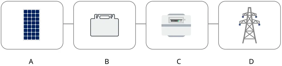
A | PV module |
B | PV inverter |
| C | Grid-connected metering device |
| D | Power grid |
About Microinverter
PV Microinverter is a module-level solar inverter that tracks the maximum DC power point of each PV module, which is known as Maximum Power Point Tracking (MPPT).
This function of module-level MPPT means that when a PV module fails or is shaded, other modules will not be affected, boosting the overall power production of the system.
Microinverter can monitor the current, voltage and power of each module to realize module-level data monitoring.
Moreover, microinverter only carries a few dozen volts of DC voltage (less than 80 volts), which reduces safety hazards to the greatest extent.
Hoymiles microinverters feature module-level monitoring. Microinverter data are collected by DTU via wireless transmission and are sent to Hoymiles motoring platform S-Miles Cloud.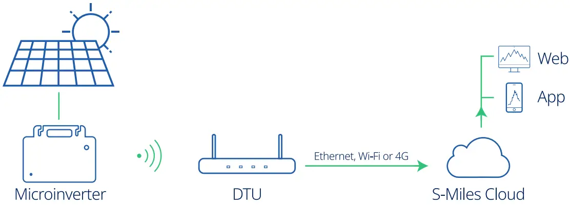
About 2-in-1 Unit
Microinverters can be divided into 1-in-1, 2-in-1, 4-in-1, etc., depending on how many PV modules are connected to them. This means that the microinverter can connect to one module, two modules and four modules respectively, as shown below.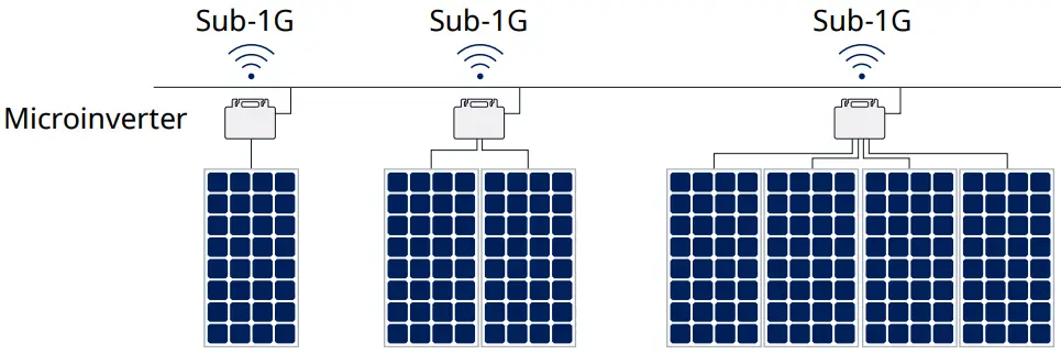
This manual is about Hoymiles 2-in-1 microinverter. With the output power up to 1000 VA, Hoymiles new HMS-1000 series rank among the highest for 2-in-1 microinverters.
Each microinverter connects to two PV modules at most with independent MPPT and monitoring, enabling greater energy harvest and easier maintenance.
About Sub-1G Technology
HMS-1000 series of microinverter adopts the new Sub-1G wireless solution which enables more stable communication with Hoymiles gateway DTU. Sub-1G technology is particularly useful for PV microinverters and is different from 2.4GHz in that it has substantially longer range and better interference suppression performance.
Range of Sub-1GHz wireless: Unlike Wi-Fi or Zigbee which both operate on the 2.4 GHz band, Sub-1GHz operates on the 868 MHz or the 915 MHz band. Generally speaking, Sub-1GHz wireless transmission covers 1.5 to 2 times longer distance than the 2.4GHz spectrum.
Interference: Sub-1GHz wireless networking can handle interference better. This is because it operates on a lower frequency, so the communication between the microinverter and the DTU is more stable. As a result, it is especially useful in industrial or commercial PV power plants.
Lower Power Consumption: Sub-1GHz wireless communication uses less power than Wi-Fi or Zigbee.
Because of the long range and better interference suppression performance, Sub-1GHz networking is particularly well-suited for rooftop PV power stations.
Highlights
– Maximum output power up to 800/900/1000 W
– Peak efficiency 96.50%
– Static MPPT efficiency 99.80%, Dynamic MPPT efficiency 99.76% in overcast weather
– Power factor (adjustable) 0.8 leading……0.8 lagging
– Sub-1G for stronger communication with DTU
– High reliability: IP67 (NEMA 6) enclosure, 6000 V surge protection
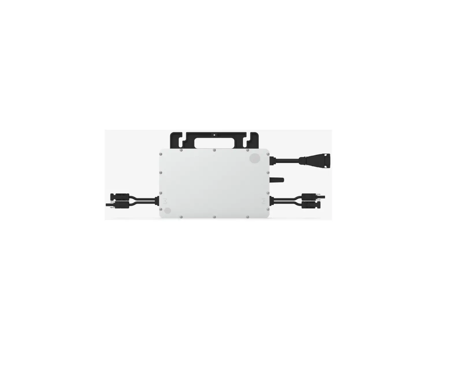
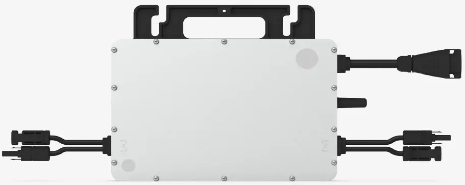
Terminals Introduction
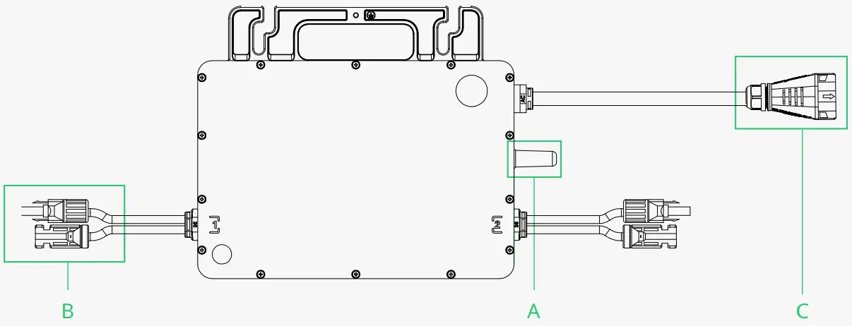
Object | Description |
A | Sub-1G Wireless Terminal |
| B | DC Connectors |
| C | AC Sub Connector |
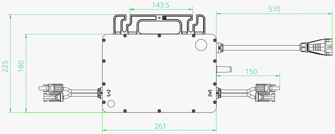
Dimensions (mm)
Installation Preparation
Position and Space Required
Please install the microinverter and all DC connections under the PV module to avoid direct sunlight, rain exposure, snow buildup, UV etc. The silver side of the microinverter should be up and facing the PV module.
Leave a minimum of 2 cm of space around the microinverter enclosure to ensure ventilation and heat dissipation.
*Note: In some countries, DTU will be required to meet local grid regulations (e.g. G98/99 for UK etc.)
Connecting Multiple PV Modules to Microinverter
General Guidelines:
- PV modules should be connected to DC input ports of a microinverter.
- Use DC extension cable when the original cable is not long enough. Please consult the local power operator to make sure that the DC cable complies with local regulations.
The typical wiring method is shown below.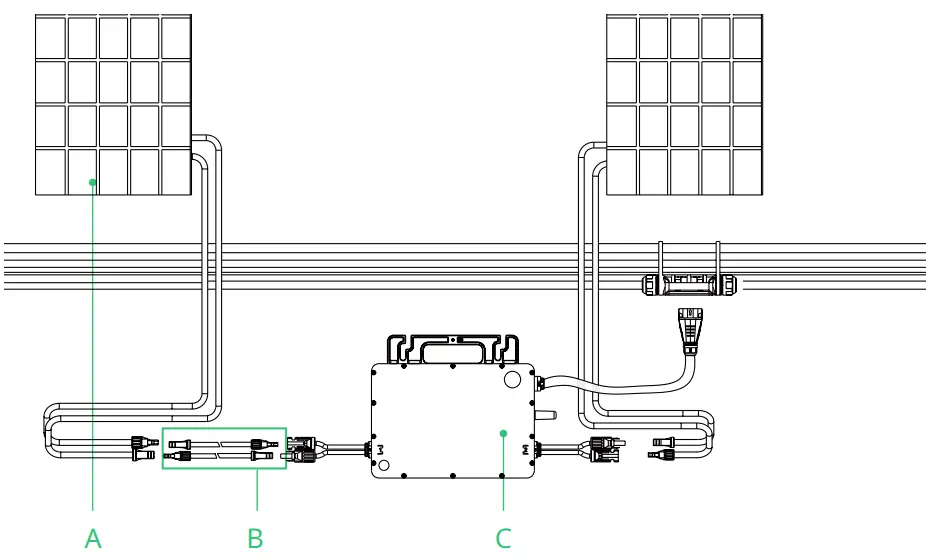
A | PV module |
B | DC extension cable |
| C | Microinverter |
Note: The voltage of modules (considering the effect of local temperature) must not exceed the maximum input voltage of the microinverter. Otherwise, the microinverter may be damaged (refer to the Technical Data section to determine the absolute maximum input voltage).
Installation Tools
| Screwdriver | Multimeter |
| Socket Wrench or Allen wrench | Marker pen |
| Diagonal pliers | Steel tap |
| Wire cutters | Cable tie |
| Wire stripper | Torque and adjustable wrench |
| Utility knife | |
| Safety glove | Dust masks |
| Protective goggles | Safety shoes |
AC Branch Circuit Capacity
Hoymiles HMS-800-2T/HMS-900-2T/HMS-1000-2T can be used with 12AWG or 10AWG AC Trunk Cable and the AC Trunk Connector which are provided by Hoymiles. The number of microinverters on each 12AWG or 10AWG AC branch shall not exceed the limit as shown below.
| HMS-800-2T | HMS-900-2T | HMS-1000-2T | Maximum over current protection device (OCPD) | |
Maximum number per 12AWG branch | 5@220 V 5@230 V 6@240 V | 4@220 V 5@230 V 5@240 V | 4@220 V 4@230 V 4@240 V | 20 A |
| Maximum number per 10AWG branch | 8@220 V 9@230 V 9@240 V | 7@220 V 8@230 V 8@240 V | 7@220 V 7@230 V 7@240 V | 32 A |
Note:
- The number of microinverters that can be connected to each AC branch is determined by the ampacity (also known as current-carrying capacity) of the cable.
- 1-in-1, 2-in-1 and 4-in-1 microinverters can be connected to the same AC branch, as long as the total current does not exceed the ampacity specified in local regulations.
Precautions
The equipment is installed based on the system design and the location of installation.
|
|
|
|
|
|
Installation location shall meet the following conditions:
|
|
Microinverter Installation
Accessories
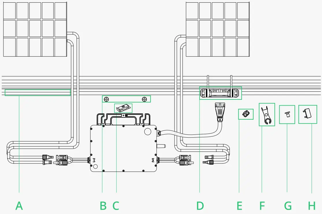
| Description | |
| A | AC Trunk Cable, 12/10 AWG Cable |
B | M8 × 25 screws (Prepared by the installer) |
| C | Grounding Electrode |
D | AC Trunk Connector |
| E | AC Trunk Port Cap |
F | AC Trunk Port Disconnect Tool |
| G | AC Trunk Port Cap |
H | AC Trunk Connector Unlock Tool |
| *Note: All accessories above are not included in the package and should be purchased separately. | |
Installation Steps
The order of Step 1 and Step 2 can be reversed according to your planned needs.
Step 1. Plan and Install the Microinverter
A ) Mark the position of each microinverter on the rail according to the PV module layout.
B ) Fix the screws on the rail.
C ) Hang the microinverter on the screws, and tighten the screws. The silver cover side of the microinverter should be facing the panel.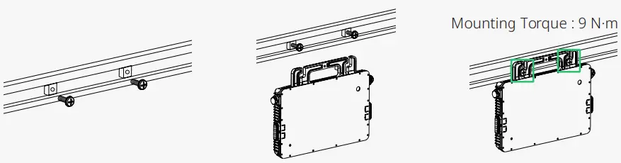
The AC cable contains earth wire, so grounding can be done directly with it. For regions that have special requirements, we offer optional grounding brackets that can be used to complete the external grounding.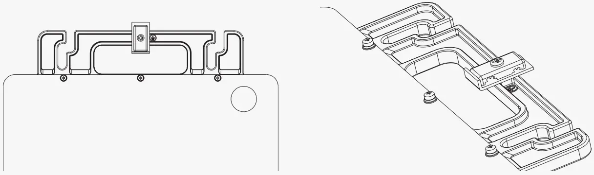
Route a continuous grounding cable through grounding brackets for each microinverter to the AC grounding electrode that conforms with local regulations.
Torque each grounding cleat screw to 2 N·m.
Note:
- Microinverter installation and DC connections must be done under the PV module to avoid direct sunlight, rain exposure, snow buildup, UV etc.
- Leave a minimum of 2 cm of space around the microinverter enclosure to ensure ventilation and heat dissipation.
- Mounting torque of the 8 mm screw is 9 N·m. Do not over torque.
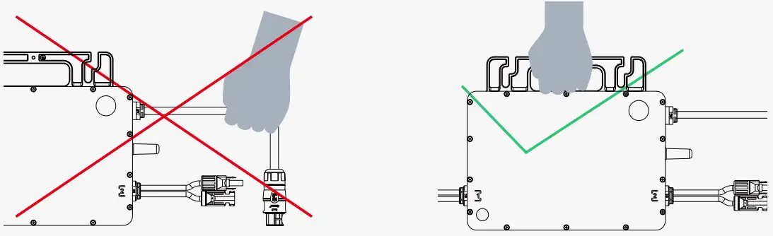
- Do not pull or hold the AC cable with your hand. Hold the handle instead.

Step 2. Plan and Build the AC Trunk Cable
AC Trunk Cable is used to connect the microinverter to the power distribution box.
A) Select the appropriate AC Trunk Cable according to the spacing between microinverters. The connectors of the AC Trunk Cable should be spaced based on the spacing between microinverters to ensure that they can properly matched. (Hoymiles provides AC Trunk Cable with different AC Trunk Connector spacing.)
B) Determine how many microinverters you plan to install on each AC branch and prepare AC Trunk Connectors accordingly.
C) Take out segments of AC Trunk Cable as you need to make AC branch.
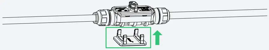
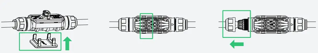
- Disassemble the AC Trunk Connector and remove the cable.
– Unlock the connector’s upper cover with AC Trunk Connector Unlock Tool.
– Loosen the three screws with the screwdriver. Untighten the cap and remove the cable.
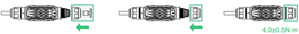
- Install the AC Trunk End Cap at one side of AC Trunk Cable (the end of AC Trunk Cable).
– Insert the AC Trunk End cap and screw the cap back to port, then tighten the cap.
– Plug the upper cover back to the Trunk connector.
- Install AC end cable on the other side of AC Trunk Cable (connected to the distribution box).
– Unlock the port upper cover, loosen the screws with the screwdriver and remove the extra cable. (Skip this step if there is no cable at this side.)
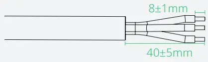
– Prepare a segment of AC cable of suitable length to connect to the distribution box, with stripping requirements fulfilled.
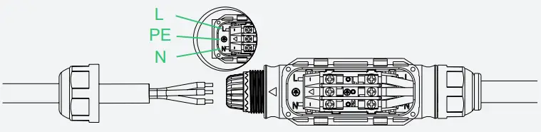
– Insert the cable into the cap in a way that the L, N and PE are in corresponding slots.- Insert the cable into the cap in a way that the L, N and PE are in corresponding slots.
– Tighten the screws, and then tighten the cap back to the port.
– Plug the upper cover back to the Trunk connector.

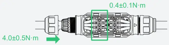
Note:
- Tightening torque of the cap: 4.0±0.5 N·m. Please do not over torque.
- Torque of locking screw: 0.4±0.1 N·m.
- Do not damage the sealing ring in the AC Trunk Connector during disassembly and assembly.
- Wires used in Hoymiles Microinverter:


D ) Repeat the above steps to make all the AC Trunk Cables you need. Then lay out the cable on the rail as appropriate so that the microinverters can be connected to the Trunk connectors.
E ) Attach the AC Trunk Cable to the mounting rail and fix the cable with tie wraps.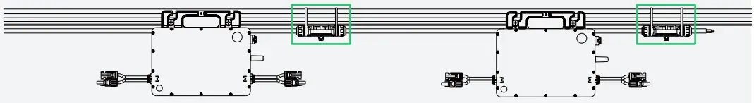
Step 3. Complete the AC Connection
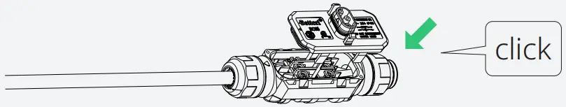
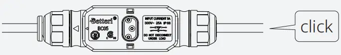
A ) Plug the AC Sub Connector of the microinverter into the AC Trunk click Connector until you hear the click.
B ) Connect the AC end cable to the distribution box, and wire it to the local grid network.
C ) Please plug the AC Trunk Port Cap click in any vacant AC Trunk Port to make it water- and dust-proof.
Note:
- Make sure that the AC Trunk Connectors are kept away from any drainage channels.
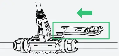
- In case you need to remove the microinverter AC cable from AC Trunk Connector, insert the AC Trunk Port Disconnect Tool into the side of AC Sub Connector to complete the removal.

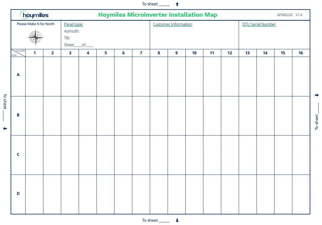
Step 4. Create an Installation Map
A) Peel the removable serial number label from each microinverter.
B) Affix the serial number label to the respective location on the installation map (please refer to the appendix).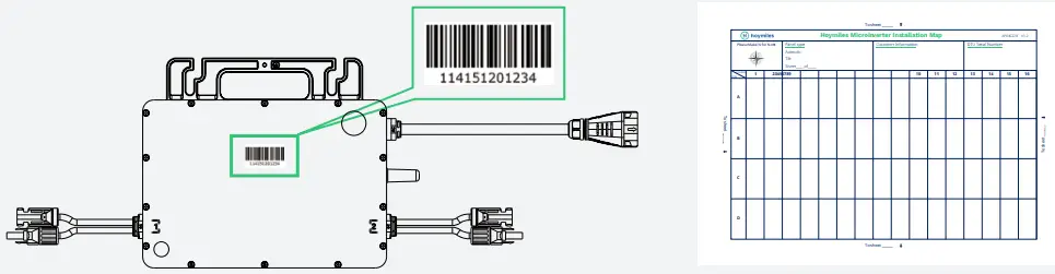
Step 5. Connect PV Modules
A) Mount the PV modules above the microinverter.
B) Connect the PV modules’ DC cables to the DC input side of the microinverter.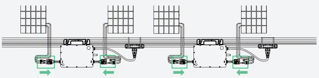
Note:
- Make sure that the AC Trunk Connectors are kept away from any drainage channels.
- In case you need to remove the microinverter AC cable from AC Trunk Connector, insert the AC Trunk Port Disconnect Tool into the side of AC Sub Connector to complete the removal.
Step 6. Energize the System
A) Turn on the AC breaker of the branch circuit.
B) Turn on the main AC breaker of the house. Your system will start to generate power in about two minutes.
Step 7. Set Up Monitoring System
Refer to the “DTU User Manual”, “DTU Quick Installation Guide”, and “Quick Installation Guide for S-Miles Cloud” to install the DTU and set up the monitoring system.
Product information is subject to change without notice. (Please download reference manuals at www.hoymiles.com)
Troubleshooting
Troubleshooting List
| Code | Alarm range | Alarm status | Handling suggestions |
| 121 | Over temperature protection |
| |
| 124 | Shut down by remote control |
| |
| 125 | Grid configuration parameter error |
| |
| 127 | Firmware error |
| |
| 129 | Abnormal bias |
| |
| 130 | Offline |
| |
| 141 | Grid | Grid overvoltage |
|
| 142 | Grid | 10 min value grid overvoltage |
|
| 143 | Grid | Grid undervoltage |
|
| 144 | Grid | Grid overfrequency |
|
| 145 | Grid | Grid underfrequency |
|
| 146 | Grid | Rapid grid frequency change rate |
|
| 147 | Grid | Power grid outage | Please check whether the AC switch, branch breaker and AC wiring is normal. |
| 148 | Grid | Grid disconnection | Please check whether the AC switch, branch breaker and AC wiring is normal. |
| 149 | Grid | Island detected |
|
| 205 | MPPT-A | Input overvoltage |
|
| 206 | MPPT-B | Input overvoltage |
|
| 207 | MPPT-A | Input undervoltage |
|
| 208 | MPPT-B | Input undervoltage |
|
| 209 | PV-1 | No input |
|
| 210 | PV-2 | No input |
|
| 213 | MPPT-A | PV-1 & PV-2 abnormal wiring |
|
| 214 | MPPT-B | PV-3 & PV-4 abnormal wiring |
|
| 215 | PV-1 | Input overvoltage | Check the input voltage of PV-1 port. |
| 216 | PV-1 | Input undervoltage | Check the input voltage of PV-1 port. |
| 217 | PV-2 | Input overvoltage | Check the input voltage of PV-2 port. |
| 218 | PV-2 | Input undervoltage | Check the input voltage of PV-2 port. |
| 301- 314 | Device failure |
|
LED Indicator Status
The LED flashes five times at start-up. All green flashes (1s gap) indicate normal start-up.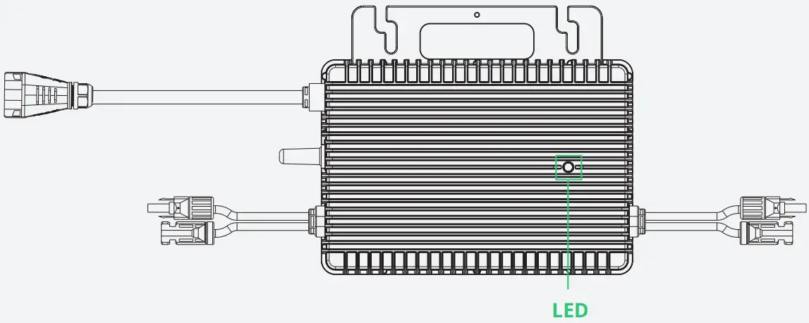
| (1) During Start-up |
|
|
| (2) During Operation |
|
|
|
|
|
| (3) Other Status |
|
*Note:
- The microinverter is powered by DC side. If the LED light is not on, please check the DC side connection. If the connection and input voltage are normal, contact your dealer or hoymiles technical support team.
- All the faults are reported to the DTU. Refer to the local DTU app or Hoymiles Monitoring Platform for more information.
On-site Inspection (For qualified installer only)
Troubleshoot a malfunctioning microinverter according to the following steps.
| 1 | Check if the utility voltage and frequency are within the respective range shown in Technical Data section of this manual. |
| 2 | Check the connection to the utility grid. Disconnect the AC and the DC power. Please note that when the inverter is in operation, disconnect the AC power first to de-energize the inverter, and then disconnect the DC power. Re-connect the PV modules to the microinverter. LED will flash red to indicate normal DC connection. Re-connect the AC power. LED will flash green for five times to indicate normal DC and AC connection. Never disconnect the DC wires while the microinverter is producing power. Re-connect the DC module connectors and wait for five short LED flashes. |
| 3 | Check the interconnection between all the microinverters on the AC branch circuit. Confirm that each inverter is energized by the utility grid as described in the previous step. |
| 4 | Make sure that every AC breaker is functioning properly and is closed. |
| 5 | Check the DC connection between the microinverter and the PV module. |
| 6 | Make sure that PV modules’ DC voltage is within the allowable range shown in the Technical Data section of this manual. |
| 7 | If the problem persists, please call Hoymiles customer support. |
| Do not try to repair the microinverter by yourself. If the troubleshooting fails, please return it to the factory for replacement. |
Routine Maintenance
- Only authorized personnel are allowed to carry out the maintenance operations and are responsible for reporting any anomalies.
- Always use personal protective equipment provided by the employer during maintenance operation.
- During normal operation, check the environmental conditions regularly to make sure that the conditions have not changed over time and that the equipment is not exposed to adverse weather conditions and has not been obstructed.
- DO NOT use the equipment if any problems are detected. Restore its working conditions after the fault is fixed.
- Conduct annual inspections on various components, and clean the equipment with a vacuum cleaner or special brushes.
| Do not attempt to dismantle or repair the microinverter! No user-serviceable parts inside for the safety and insulation reasons! |
| The AC output wiring harness (AC drop cable on the microinverter) cannot be replaced. The equipment should be scrapped if the cord is damaged. |
| Maintenance operations must be carried out with the equipment disconnected from the grid (power switch open) and the PV modules shaded or isolated, unless otherwise indicated. |
| Never clean the equipment with rags made of filamentary or corrosive materials to avoid corrosion and electrostatic charges. |
| Do not attempt to repair the product. All repairs should be done using only eligible spare parts. |
| If all the microinverters are connected to the DTU-Pro-S, the DTU can limit the output power imbalance of all the microinverters between phases to below 3.68 kW if required. Please refer to “Hoymiles Technical Note Limit Phase Balance” for more details. |
| Each branch should have a circuit breaker. Central protection unit is unnecessary. |
Microinverter Replacement
| a. How to remove the microinverter |
|
|
|
|
|
|
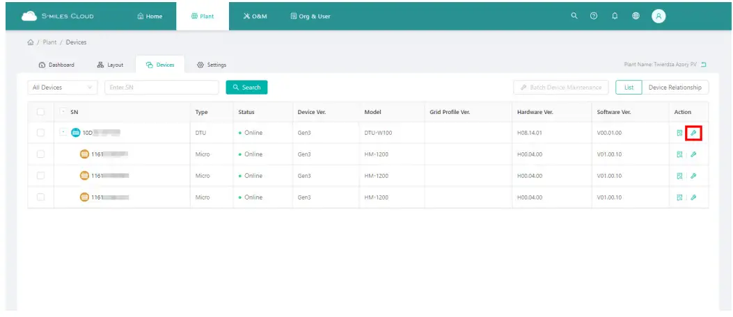
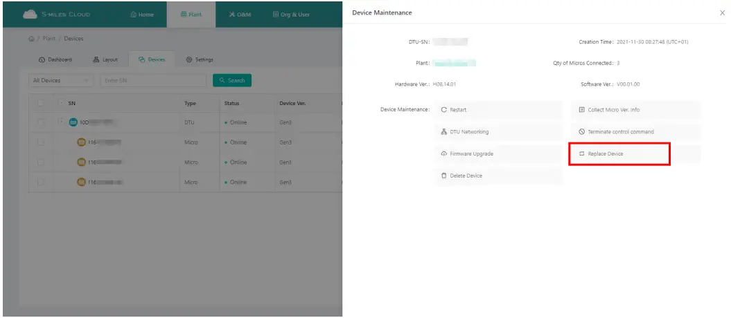
| b. How to replace the microinverter in monitoring platform |
|
|
|
Decommission
Decommission
Disconnect the inverter from DC input and AC output, remove all connection cable from the microinverter, and remove the microinverter from the frame.
Please pack the microinverter in the original packaging. If the original packaging is no longer available, you can use a carton box that can hold 5 kg and can be fully closed.
Storage and Transportation
Hoymiles packages are specially designed to protect components so as to facilitate transportation and subsequent handling. Transportation of the equipment, especially by road, must be done in a way that can protect the components (particularly the electronic components) from violent shocks, humidity, vibration, etc. Please dispose of the packaging elements in appropriate ways to avoid unforeseen injury.
Please examine the conditions of the components to be transported. Upon receiving the microinverter, you should check the container for any external damage and verify the receipt of all items. Please call the carrier immediately if there is any damage or if any parts are missing. In case of any damage caused to the inverter, contact the supplier or authorized distributor to request a repair/return and ask for instructions regarding the process.
The storage temperature range of microinverter is -40 to 85°C.
Disposal
- If the equipment is not used immediately or is stored for a long period of time, make sure that it is properly packed. The equipment must be stored indoors with good ventilation and without any potential damage to the components of the equipment.
- Take a complete inspection when restarting the equipment after it has stopped operation for a long time.
- Please dispose of the microinverters properly in accordance with local regulations after they are scrapped because of potential harms to the environment.
Technical Data
| If all the microinverters are connected to the DTU-Pro-S, the DTU can limit the output power imbalance of all the microinverters between phases to below 3.68 kW if required. Please refer to “Hoymiles Technical Note Limit Phase Balance” for more details. |
- Verify that the voltage and current specifications of the PV module match those of the microinverter. · The maximum open circuit voltage rating of the PV module must be within the operating voltage range of the microinverter. · We recommend that the maximum current rating at MPP should be equal to or less than the maximum input DC current.
- The output DC power of PV module shall not exceed 1.35 times of the output AC power of the microinverter. Refer to “Hoymiles Warranty Terms & Conditions” for more information.
Appendix 1:
Installation Map
Appendix 2:
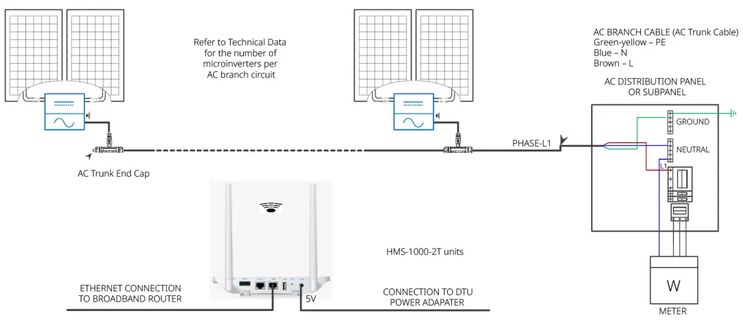
WIRING DIAGRAM – 230VAC SINGLE PHASE:
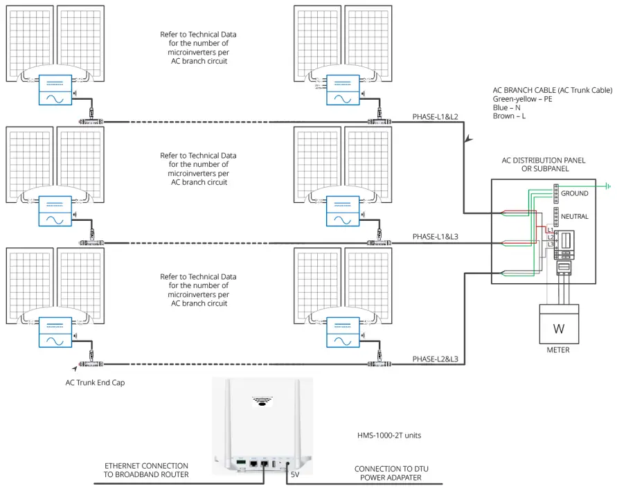
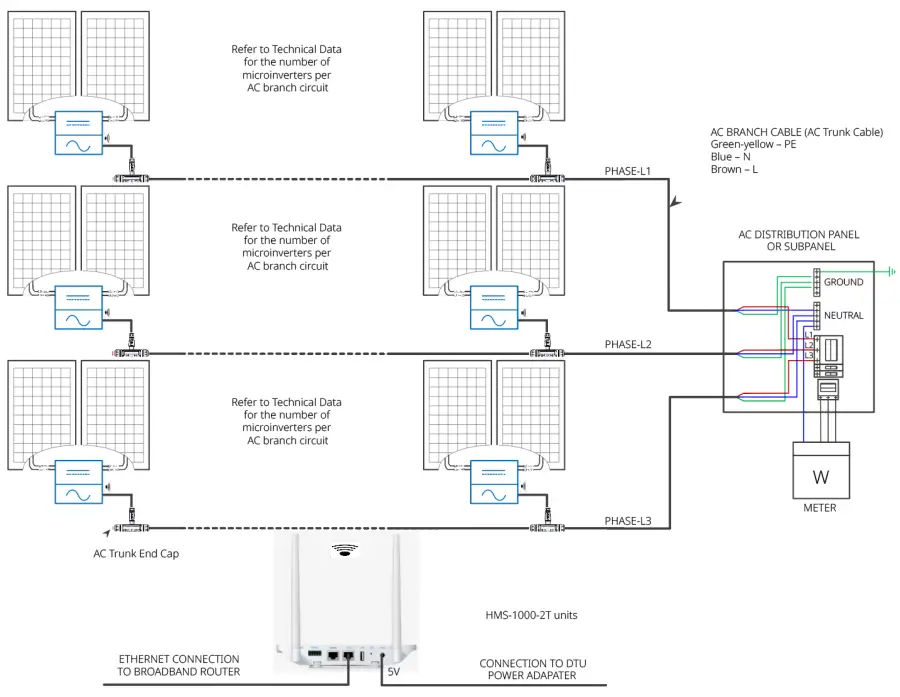
WIRING DIAGRAM – 230VAC / 400VAC THREE PHASE:
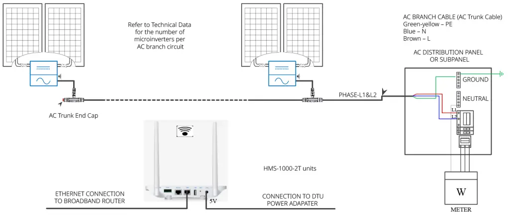
WIRING DIAGRAM –120VAC / 240VAC SPLIT PHASE:
WIRING DIAGRAM – 120VAC / 208VAC THREE PHASE: