![]()
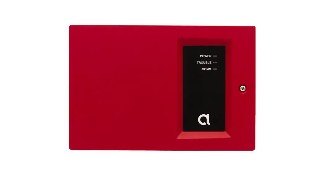
 BAT-Fire™ Communicator
BAT-Fire, AT&T™ (BAT-FIRE-ATT)
BAT-Fire, Verizon™ (BAT-FIRE-VZ)
Scan QR for most up to date manual, features, and compatibility

BAT-Fire is a device that connects to an intrusion or fire alarm control panel (FACP) and provides central station alarm reporting.
Features
- Supports 12V and 24V regulated FACPs
- Alarm capture via phone line interface or standard FACP points
- Supports Contact ID (CID) reporting format
- Dual-Path: Ethernet (primary) with Cellular (backup)
- Sole Path: Ethernet or Cellular
- Platform visibility through AlulaConnect™
- Trouble event detection and reporting
- Four programmable input/output ports
- At-a-glance system status via front-panel LEDs
- UL 864 10th edition commercial fire certification
- ULC-S559 commercial fire certification
- UL 1610 commercial burg certification
- ULC-S304 commercial burg certification (Security Level II installations)
Operation
Phone line capture
BAT-Fire provides two PSTN interfaces for the FACP’s DACT phone line connections. BAT-Fire’s DACT phone interface connection provides phone line voltage, dial tone, ringback tone, and all required CID protocol signaling. The BAT-Fire receives CID events from the FACP’s DACT and then relays the CID events to the central station receiver.
Point capture
The BAT-Fire provides inputs that can be used to monitor an FACP’s alarm, supervision, and trouble points. In this topology, BAT-Fire inputs will be connected to the FACP points. BAT-Fire will continually monitor the state of the FACP points. A state change on a BAT-Fire monitored FACP point will be reported to the central station. (Refer to the Programming section describing how to set up a BAT-Fire input for FACP point capture.)
Note: for UL 864 10th edition, this configuration may only be used for panels with one input zone. 9th edition and earlier permitted this method for multiple protection zones.
Central station communication
The BAT-Fire can be configured to provide dual path connectivity using Ethernet/broadband and cell or single path connectivity using either Ethernet/broadband or cell to Bosch Conettix D6100IPv6 receivers at the central station.
Installation and Wiring
- Set up an account in the AlulaConnect portal.
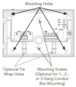
- Mount the BAT-Fire using the guidelines listed below to meet UL 864/UL 1610/NFPA or ULC-S559/ULC-S304. Use the mounting holes on the backplate.
- Install the cellular antenna.
- Power down the FACP.
- Wire the BAT-Fire to the FACP. (See wiring diagrams on the following pages.) All wiring must be performed in accordance with NFPA 70/72 or CSA C 2.1 (Safety Standard for Electrical Installations, Canadian Electrical Code, Part I, Section 32).
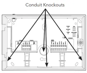
Note: 1/2” conduit should be used. Only one conduit knockout is to be used for wiring. Multi-conductor wire connections should follow best practices using pigtail or crimp connectors. To meet UL 864/UL 827/UL 681/NFPA or ULC-S559/ULC-S524/ULC-S561/ULC-S301/302, ensure the following:
• BAT-Fire must be installed in accordance with UL 864/ NFPA 70/72 or ULC-S559/ULC-S524/ULC-S561.
• BAT-Fire must be mounted in the same room as the FACP.
• All wiring between BAT-Fire and FACP has maxed 20 ft for UL 864 and max 18 m for ULC-S559. These wire length guidelines must be used for both burg and fire installations.
• Run all wiring between BAT-Fire and FACP through a non-rigid metallic conduit (Canada) and non-rigid conduit (US).
• All equipment used for the IP connection (such as the router, hub, modem, etc.) shall be UL/c-UL listed, and be provided with 24-hour standby power. - For dual or sole path Ethernet, plug in the Ethernet cable.
- Power up the system. After 1-2 minutes, verify the Ethernet and Cellular LEDs. For Ethernet installs, the ETHERNET LED should be on. For cellular installs, the CELLULAR LED should be on, or displaying a short blink sequence (dual-path mode). Verify a minimum of two signal bar LEDs are displayed. (See Operation and Indicator Overview section for signal strength.)

- Physical installation is complete.
- Press the Config button on the BAT-Fire for 2 seconds to enable programming. Program the BAT-Fire via AlulaConnect (see Programming section).
- Close the cover. Confirm POWER, TROUBLE, and COMM LEDs are green.
- After installing BAT-Fire, or modifying any FACP programming, verify proper operation and reporting of all event codes using your FACP installation manual. Burglary installs must have cover tamper enabled and must be tested yearly.
 To meet UL 864/UL 827/UL 681/NFPA or ULC-S559/ULC-S524/ULC-S561/ULC-S301/302, ensure the following:
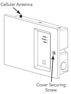
Figure 1. Phone Line Capture Wiring
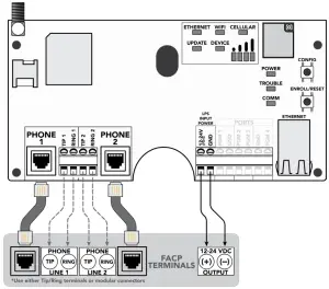
- Both Phone lines 1 and 2 must be connected to the FACP. The FACP may be configured to supervise the phone lines.
- Most FACPs can be supported for event reporting as long as it provides Tip & Ring connection and transmit events in Contact ID format.
- Do not connect telephone company lines to BAT-Fire’s phone line connections.
- It is recommended to use separate wiring for each Tip & Ring connection.
- Failures and Troubles are communicated to FACP via the BAT-Fire dropping voltage to Phone 2. Refer to the Programming section on how to configure Phone 2 trouble triggers.
- Stranded wire gauge range: 24-14AWG.
Figure 2. Point Capture Wiring
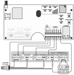
- Refer to the Programming section on how to configure BAT-Fire’s PGM1, PGM2, and PGM3 for FACP point capture.
- Refer to the Programming section on how to configure BAT-Fire’s PGM4 as a trouble trigger. PGM4 is an open-collector output.
- This figure shows one possible configuration between BAT-Fire and the FACP. A relay may not be required. Refer to your FACP installation manual. If a relay is required, use a UL 864 or ULC-S527 listed relay.
- Use 4.7k ohm 1/4 Watt minimum resistors (not included).
- PGM ports are not supervised.
- For UL 864 10th edition, this configuration may only be used for panels with one input zone. 9th edition and earlier permitted this method for multiple protection zones.
Programming
Programming via AlulaConnect
| Table 1: PARAMETERS FOR UL 864 & UL 1610 COMPLIANCE (USA) | ||||||
| NOTICE TO INSTALLERS, AUTHORITIES HAVING JURISDICTION, AND OTHER INVOLVED PARTIES: | ||||||
| This product incorporates field-programmable software. In order to comply with the requirements in the Standard for Control Units and Accessories for Fire Alarm Systems, UL 864, and/or Standard for Safety: Central-Station Burglar Alarm-Units, UL 1610, certain programming features or options must be limited to permitted settings or not used at all as indicated below. | ||||||
| Programmable Parameter | Situation | Possible Settings | Default Settings | UL 864 Permitted Settings | UL 1610 Permitted Settings | Notes |
| Supervision Preference (Comm Trouble Supervision) | IP with Cell Backup | 1 min – 6 hours | 6 hours | 6 hours or shorter | Primary: 200 seconds Backup: 6 hours | If the primary path fails’ system supervises secondary path at the primary interval. |
| Sole Path IP | 1 min – 6 hours | I hour | 1 hour or shorter | 200 seconds | Turn off cellular supervision Turn off the virtual interface supervision for both primary and backup cellular | |
| Sole Path Cell | 1 min – 6 hours | I hour | shorter | 1 hour or 200 seconds | Turn off Ethernet supervision Turn off virtual Turn interface supervision for both primary and backup Ethernet | |
| Remote Programming | On-site or Remote | Enabled or Disabled | Disabled | Disabled | Enabled or Disabled | If Disabled, Installer must press Config button onsite |
| Phone 2 Trouble Trigger | If using Phone Line capture (Figure 1) | Power Fail Cover Tamper Cell Fail Ethernet Fail CS Fail CS Trouble | Cover Tamper CS Fail. er CS Trouble | Cover Tamper CS Fail | Cover Tamper CS Fail | FIVE 1- |
| My Enabled Trouble: BAT-Fire drops Phone 2 line voltage | ||||||
| PGM4 Port Trouble Trigger | If using Point Capture 2) ( Figure 2 | Power Fail Cover Tamper Cell Fail Ethernet Fail CS Fail CS Trouble | CS Fail | Cover Tamper CS Fail | Cover Tamper CS Fail | Figure 2 |
| BAT-Fire PGM4 Output (Any Enabled Trouble) connected to FACP Trouble Input | ||||||
* If Remote Programming is disabled, updates to site-specific parameters and BAT-Fire firmware are only permitted when the Config button on the BAT-Fire is pressed for 2 seconds.
- If Commercial Burg is selected, the more restrictive of the Fire and Burg timings will be used.
- Earlier editions of NFPA require supervision settings of 5 minutes.
- UL 864 10th edition permits the point capture configuration for FACPs protecting only a single zone; the 9th edition permits point capture for multi-zone FACPs.
| Table 2: PARAMETERS FOR ULC-S559 & ULC-S304 COMPLIANCE (CANADA) | ||||||
| NOTICE TO INSTALLERS, AUTHORITIES HAVING JURISDICTION, AND OTHER INVOLVED PARTIES: | ||||||
| This product incorporates field-programmable software. In order to comply with the requirements in the Standard for Equipment for Fire Signal Receiving entries and Systems, ULC-S559-13-R2018 and/or the Standard for Control Units, Accessories and Receiving Equipment for Intrusion Alarm Systems, ULC-S304:2016-REV1, certain programming features or options must be limited to permitted settings or not used at all as indicated below. | ||||||
| Programmable Parameter | Situation | Possible Settings | Default Settings | ULC•S559 Permitted Settings ULC•S304 | Permitted Settings | Notes |
| Supervision Preference (Comm Trouble Supervision) | IP with Cell Backup | 1 min – 6 hours | 6 hours | Primary: 3 minutes or shorter Backup: 6 hours | Primary: 180 seconds Backup: 180 seconds | For ULC-S559, if primary path fails, system supervises secondary path at the primary interval. |
| Sole Path IP | 1 min – 6 hours | 1 hour | 3 minutes or shorter | 180 seconds | Turn off cellular supervision Turn off the virtual interface supervision for both primary and backup cellular | |
| Sole Path Cell | 1 min – 6 hours | 1 hour | shorter | 3 minutes or 180 seconds | Turn off Ethernet supervision Turn off virtual Turn interface supervision for both primary and backup Ethernet | |
| Remote Programming• | On-site or Remote | Enabled or Disabled | DIsabled | Enabled or Disabled | Enabled or Disabled | If Disabled, Installer must press Config button onsite |
| Phone 2 Trouble Trigger | If using Phone Line capture (Figure 1) | Power Fail per Cover Tamper Cell Fail’ Ethernet Fail CS Fail CS Trouble | Cover Tamper CS Fail CS Trouble | Cover Tamper CS Fail | Cover Tamper CS Fail | Figure 1: Any Enabled Trouble: BAT-Fire drops Phone 2 line voltage |
| PGM4 Port Trouble Trigger | If using Point Ca (Figure 2) | Power Fail Cover Tamper Cell Fail Ethernet Fail CS Fail CS Trouble | CS Fail | Cover Tamper CS Fail | Cover Tamper CS Fail | Figure 2: BAT-Fire PGM4 Output (Any Enabled Trouble) connected to FACP Trouble Input |
* If Remote Programming is disabled, updates to site-specific parameters and BAT-Fire firmware are only permitted when the Config button on the BAT-Fire is pressed for 2 seconds.
- If Commercial Burg is selected, the more restrictive of the Fire and Burg timings will be used.
- ULC-S304 requires 128-bit encryption or better. For active communications, encryption shall be enabled at all times.
Programming BAT-Fire Phone 2 trouble triggers
- Select “Edit” to the right of Phone 2
- Check all desired Phone 2 triggers
• Power Fail
• Cover Tamper
• Cell Fail
• Ethernet Fail
• Central Station Fail
• Central Station Trouble - Select “Save”
Programming BAT-Fire PGMx port for FACP point capture
- Select “Edit” on the desired input port
- Select “Configure as Input”
- Enter required configuration input data
• Sensor Type
• Report Code
• Zone Number
• Input Name - Select “Save”
Programming BAT-Fire PGM4 port as trouble trigger
- Select “Edit” on the desired output port
- Select “Configure as Output”
- Name output as desired
- Check all desired trouble triggers
• Power Fail
• Cover Tamper
• Cell Fail
• Ethernet Fail
• Central Station Fail
• Central Station Trouble - Select “Save”
Programming BAT-Fire central station receiver(s)
- Select primary and backup (optional) receivers
- Adjust Supervision Interval based on wiring mode
• 6 hours (default) complies with UL 864 10th edition requirement for dual-path communications
• For specific AHJ guidance, sole path mode, or ULC-S559 compliance, refer to Table 1 for Supervision Interval settings - Select “Save”
Operation and Indicator Overview
Events are reported to the central station receivers and the Alula platform event system. All events use Contact ID reporting codes.
To enter programming press the Config button on the BAT-Fire for 2 seconds.
- With the BAT-Fire cover open, it will remain in programming mode for 1 hour.
- Close the cover. The programming mode will exit in 90 seconds.
Enroll/Reset button
- Hold for 5 seconds to reset the BAT-Fire
- Hold for 30 seconds to factory default the BAT-Fire
* All LEDs flash on then off at 5 seconds and again at 30 seconds when the Enroll/The reset button is held down. This indicates that the button has been pressed for a sufficient amount of time.
LED indicators
| LED | Indication |
| Power | Place when power is present |
| Trouble | Green – system ok Yellow – input voltage < 8,/, or – cell connection has failed, or – Ethernet connection has failed, or cove’s open |
| Comm | Green – central station receiver(s) all ok Yellow – central station receiver(s) trouble Off – all central station received’) have failed |
| Ethernet | Off – interface not used Flashing – attempting connection using this interface On – connected using this interface |
| Wi-Fi | Unused |
| Cellular | Off – cell is not registered Flashing – lest connection test failed On – connected usng this interface Short blink – connected via Ethernet, last cell connection test successful |
| Update | Off – labware update available Mashing- firmware update is in progress On – firmware is up to date |
| Device | Unused |
Cellular signal bar LEDs indicate the quality of the cellular connection. A minimum of two signal bar LEDs is recommended.
| Number of Signal Bar LEDs Lit | Cellular Signal Strength |
| 0 | Bad |
| 1 | Marginal |
| 2 | Acceptable |
| 3 | Good |
| 4 | Best |
BAT-Fire will relay any signal sent from the panel it is connected to. Additionally, the following signals can be generated from the BAT-Fire directly.
Pro Tips
- The BAT-Fire is a commercial life safety communicator and requires a reliable and consistent cellular connection. Always follow best installation practices regarding mounting location and location of the antenna to achieve and maintain the highest possible signal level. The signal bar indicators are engineered to ensure a durable, trouble-free installation.
- Cellular antennas need to be in free air to communicate. Cellular antennas should not be mounted inside a metal enclosure.
- Cellular antenna options for enhanced performance:
Indoor:
o Taoglas™ TG.30.8113
Outdoor:
o Taoglas OMB.6912.03F21
Troubleshooting
| Symptom | Troubleshooting Steps |
| Ethernet LED Off | 1, Confirm cable connected. 2. Ensure the router is powered. 3. Ensure UDP ports 1234 and 1235 are open on router/modem settings. 4. Ensure account 6 is properly configured. |
| Cellular LED Off | 1. Verify sufficient signal strength for cellular (see cellular signal bar table in Operation and Indicator Overview section). 2 Ensure the account is properly configured. |
| Comm LED Yellow | 1 Verify the reporting path and ensure the receiver is properly configured. 2 Contact Mule for further technical support- |
| No Alann CS Reports | 1. Ensure FACP wiring is correct. 2 Ensure the FACP is configured properly. •If telco reporting, ensure FACP is set-up for CID reporting_ •if point capture reporting, ensure FACP is set up to trip appropriate relays. 3 Ensure account 6 is properly configured for event relay. 4 Contact Alula for further technical support- |
| Cellular Signal Strength | 1. Ensure the antenna is securely threaded onto the BAT-Fire antenna connector. 2 Reposition the unit (move or rotate). 3 Move the unit/antenna higher in the building_ 4 Move the unit/antenna away from the metal object: (appliances, duct. stucco walls, Mors). 5 Move the unit/antenna closer to a window. 6 Install one of the higher-performance antenna options (see Pro Tops section). |
| Glossary | |
| Capture | Sensing a status or condition |
| DACT | Digital Alarm Communicator Transmitter that reports on phone lines |
| FACP | Fire Alarm Control Panel |
| I/O Port | A programmable input or output on BAT-Fire named PGM1-PGM4 |
| Line | A phone line, used for reporting alarm data |
| Phone Line Capture | The operation of the BAT-Fire connecting to the FACP phone ports and emulating the central station |
| LPS | Limited Power Source |
| NFPA | National Fire Protection Association |
| Open Collector | An output that. when engaged, shunts current to ground |
| Point | A single FACP output that is either on or off |
| Point Capture | The operation mode of BAT-Fire connected to the FACP output) and sensing a trouble or alarm condition. Additionally, the operation of the FACP connected to a BAT-Fie output and sensing a trouble or communication condition |
| PSTN | Public Switched Telephone Network, aka POTS – Plain Old Telephone Service |
| Relay | An electrically operated switch that isolates the control signal (.e. FACP output) from the switched circuit lo. BAT-Fire input) |
| Trigger | An event that causes a BAT-Fire output to change state |
Specifications
| Physical | |
| Housing Dimensions Weight Mounting Fasteners Pilot Hole for Screw into Wood Pilot Hole for Wall Anchor Cover Securing Screw Antenna Wire Gauge Range | 8.6 x 5.8 x 2.2 inches [21.8 x 14.6 x 5.5 cm] 13.2 ounces [375 g] #6 screws and wall anchors [included] Ø 1/8in [3mm] Ø 3/16in [4.7mm] #6 screw [included] External [included] 24-14AWG |
| Device Specification | |
| Reported Indications Current Draw Compatible Input Voltage Range Programmable Output Current Maximum | Cover Tamper 185mA [Nominal] @ 12VDC, 100mA [Nominal] @ 24VDC 10-28VDC Will shunt up to 75 mA into the ground |
| Environmental | |
| Operating Temperature Maximum Humidity | 32°F to 120°F [0°C to 48.9°C] 93% non-condensing relative humidity |
| Models | |
| BAT-FIRE-ATT BAT-FIRE-VZ | BAT-Fire, AT&T BAT-Fire, Verizon Note: the only difference between the models is the cellular carrier. |
| Certification | |
| Safety Standards Radio Cellular California State Fire Marshal NY Fire Marshal | AT&T, Verizon |
Specifications subject to change without notice
FCC NOTICE
This device complies with Part 15 of the FCC rules. Operation is subject to the following two conditions:
- This device may not cause harmful interference.
- This device must accept any interference that may be received, including interference that may cause undesired operation.
Changes or modifications not expressly approved by Alula could void the user’s authority to operate this equipment.
RF Exposure:
To satisfy FCC RF Exposure requirements for mobile and base station transmission devices, a separation distance of 20 cm or more should be maintained between the antenna of this device and persons during operation. To ensure compliance, operation at closer to this distance is not recommended.
Cellular
FCC ID: XMR2020BG95M1
IC NOTICE
This device complies with Industry Canada license-exempt RSS
standard(s). Operation is subject to the following two conditions:
- This device may not cause interference, and
- This device must accept any interference, including interference that may cause undesired operation of the device.
TRADEMARKS
Alula, BAT-Fire, and AlulaConnect are trademarks owned by Alula Holdings, LLC. AT&T is a trademark of AT&T Intellectual Property II, L.P. Verizon is a trademark of Verizon Trademark Services LLC. Taoglas is a trademark of Taoglas Group Holdings Limited. Unless otherwise specified, all trademarks in this manual are protected under trademark law. You agree not to copy, use or otherwise infringe upon these marks. Alula manuals may also contain other product, service, and/or company names that may be trademarks of their respective owners.
Patents Pending
47-00009 • Rev A • 2021-09-15
Tech Support Line • (888) 88-ALULA • (888) 882-5852
alula.com


