![]() H-1227, H-3637 H-5529
H-1227, H-3637 H-5529
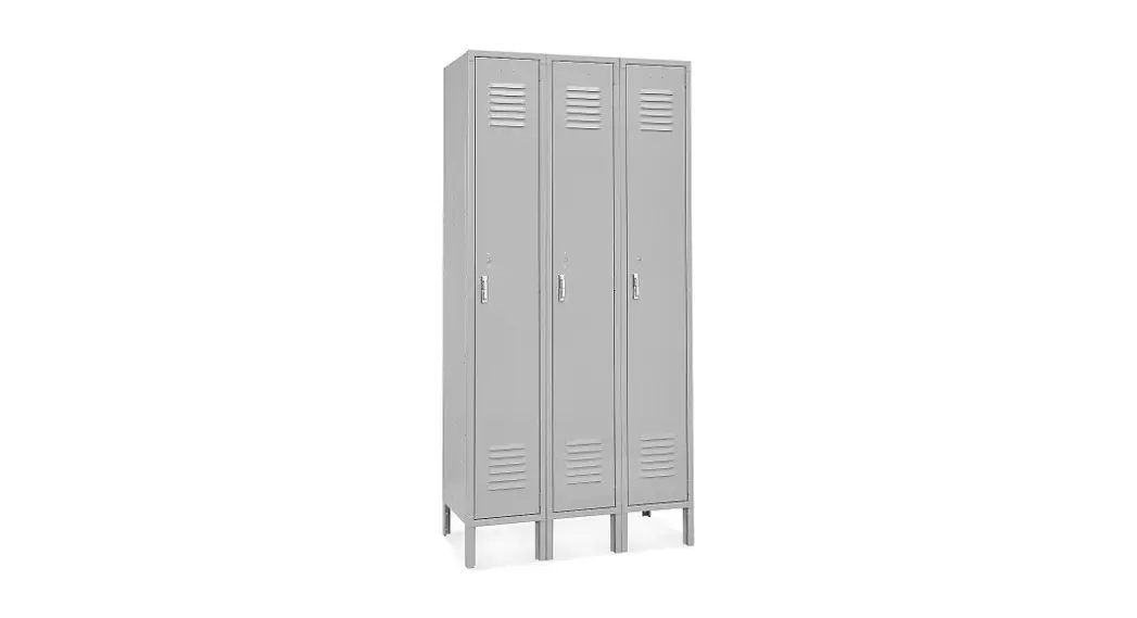
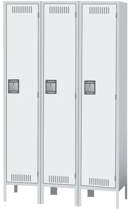
SINGLE TIER LOCKER THREE-WIDE
1-800-295-5510
uline.com
TOOL NEEDED
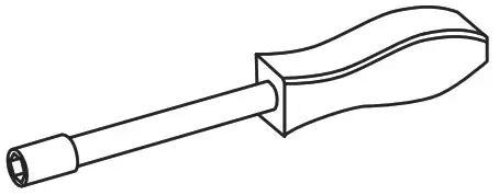
11/32″ Nut Driver (Included)
 WARNING! Some parts may have sharp edges. Care must be taken when handling various pieces to avoid injury. For your safety, wear work gloves when assembling.
0821 IH-1227
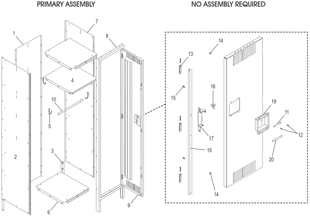
PARTS
| # | DESCRIPTION | QTY. |
| 1 | Back | 3 |
| 2 | Left Side | 2 |
| 3 | Rear Leg | 4 |
| 4 | Shelf | 3 |
| 5 | Coat Hook | 9 |
| 6 | Top/Bottom Shelves | 6 |
| 7 | Right Side | 2 |
| 8 | Door Frame Assembly | 3 |
| 9 | Locker Door | 3 |
| 10 | Coat Rod (For H-1227 and H-5529 only) | 3 |
| # | DESCRIPTION | QTY. |
| 11 | Number Plate | 3 |
| 12 | Plush Plug | 6 |
| 13 | Latch And Spring | 9 |
| 14 | Bumper | 6 |
| 15 | Dart Clip | 6 |
| 16 | Locking Channel | 3 |
| 17 | Lock Receiver | 3 |
| 18 | Reinforcement Tab | 3 |
| 19 | Recessed Handle | 3 |
| 20 | Logo Plate | 3 |
ASSEMBLY
 |  |  |
ASSEMBLING MAIN PANELS![]() NOTE: Do not tighten bolts until unit is completely assembled.
NOTE: Do not tighten bolts until unit is completely assembled.
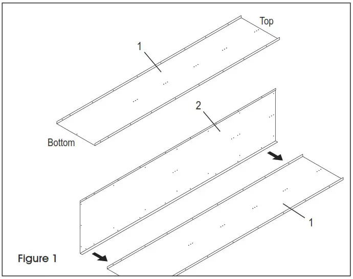
- Locate and separate the left and right sides (2 and 7). Identify the top of each panel. The top of each panel has three holes instead of one.
- Place back (1) on a protected flat surface so that the flanges face upward.
- Bolt left side (2) to the back (1) so that side flange fits around back (use 7 bolts and nuts – nuts to the inside). Do not use the bottom 2 holes; these will be used for attaching legs in step 8. (See Figure 1)
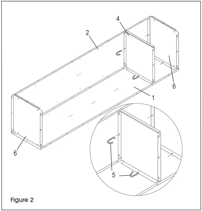
- Attach top and bottom (6) to side (2) and back (1) as shown (See Figure 2). Bolt shelf (4) to back and side.
 NOTE: Save one right side for step 7.
 - Bolt an intermediate side and back panel to the flange of the first locker (use 7 bolts and nuts – as in step 3). Bolt shelf (4) to back and side. Attach top and bottom (6) to the first intermediate side and back panel.NOTE: A left or right side may be used as an intermediate side.
- Next attach the remaining intermediate side and back to the flange of a second back. Then attach the remaining shelf, top, and bottom to the intermediate side.
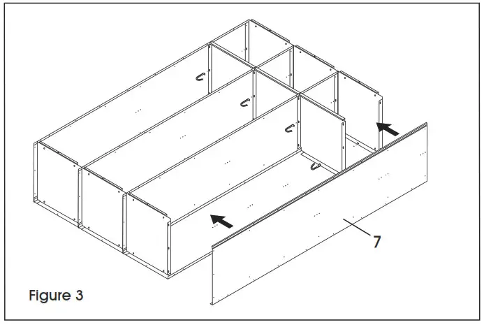
- Bolt right side (7) to the back so that side flange fits around back. Attach side to top, bottom and shelf. (See Figure 3)
- Attach coat hooks (5) to each locker’s left side and back panel:
•Side 3rd & 4th holes below shelf (6th, 7th holes down from top).
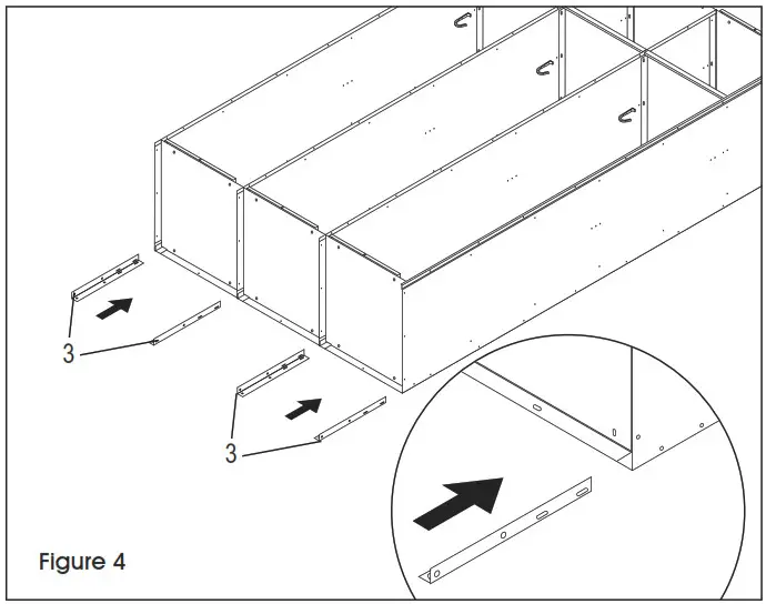
•Back 2nd & 3rd holes below shelf (5th, 6th holes down from top). (See Figure 2) - Insert the legs (3) into corners between the bottom and the side. Bolt the leg to the side using two bolts and nuts per leg. (See Figure 4)
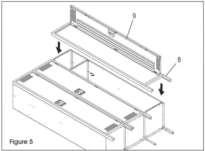
- Place door and frame assembly (8 & 9) over the locker body. Make certain the body sides are inside the frame and not between the frames. Attach top to frame header and bottom to frame sill (one bolt each). Finish by attaching the door and frame assembly to the sides of the locker body (bolts will be shared with the door and frame on either side of them). (See Figure 5) If joining a 3-wide unit beside another unit see JOINING UNITS TOGETHER below.
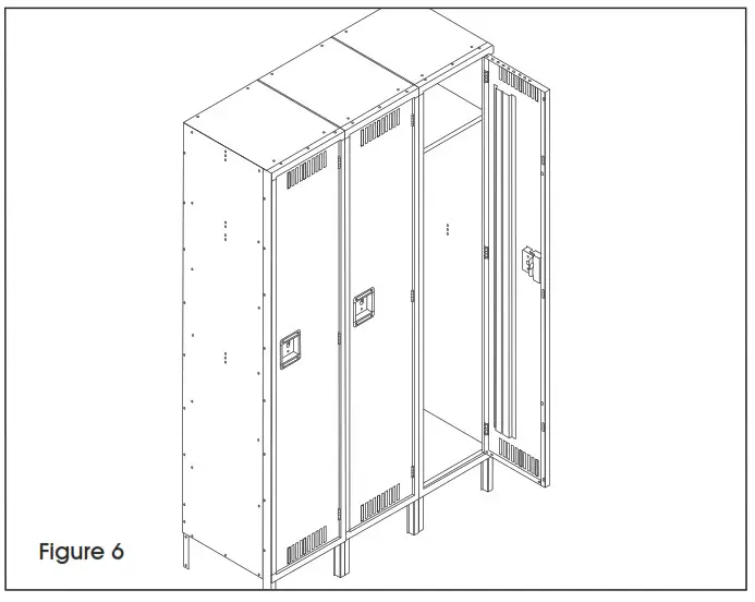
- Stand unit upright, and place in the desired location. If joining units together, remove temporary bolts in frames and bolt adjacent units together through frames. Check and tighten all permanent bolts. (See Figure 6)NOTE: If the temporary bolts are not removed before the frames are joined side by side, the frames will have a 1/8″ gap between them.
- For H-1227 and H-5529: Place non-slotted end of coat rod (10) over projecting tab of top left coat hook. Slide the slotted end of the coat rod over the projecting tab in the right coat hook and turn 90° to secure it.
 |  |  |
JOINING UNITS TOGETHER
1. If joining a 3-wide unit beside another unit, temporarily install a bolt and nut into the third and sixth holes down from the top of the outer frame(s) that will be joined to the adjacent locker frame(s). (See Figure 6) The center locker frame can be bolted completely.
SECURING UNITS
- Anchor units to wall or floor. Units are not intended to stand free and may topple if not secured. (Units standing back to back should be bolted together.)
CAUTION! Care must be taken to assure that lockers are set plumb and true before anchoring. - If units are not pre-numbered, an optional number plate (11) may be attached with two #6 x 5/16 drive screws or push plugs (12).
![]()
1-800-295-5510
uline.com


