TECHNICAL MANUAL
SUPAflo EVO
Condensing Gas Fired Water Heater![]()
Technical Document for SUPAflo Water Heater

![]()
Please read and understand these instructions before commencing installation and leave this manual with the customer for future reference.
Andrews. Built to perform.
Andrews Water Heaters
Reproduction of any information in this publication by any method is not permitted unless prior written approval has been obtained from Andrews Water Heaters.
Andrews SUPAflo EVO has been designed and manufactured to comply with current International standards of safety. In the interests of the health and safety of personnel and the continued safe, reliable operation of the equipment, safe working practices must be employed at all times. The attention of U.K. users is drawn to their responsibilities under the Health and Safety Regulations 1993.
All installation and service on the Andrews SUPAflo EVO must be carried out by properly qualified personnel, and therefore no liability can be accepted for any damage or malfunction caused as a result of intervention by unauthorised personnel.
The Andrews Water Heaters policy is one of continuous product improvement, and therefore the information in this manual, whilst completely up to date at the time of publication, may be subject to revision without prior notice.
Further information and assistance can be obtained from:
Customer support
Monday – Friday
8am – 5pm
Sales: 0345 070 1055
Technical: 0345 070 1057
Email: [email protected]
Website: www.andrewswaterheaters.co.uk
Twitter: @andrewsWH
Copyright Andrews Water Heaters 2022
1 General and Safety Information
1.1 General information
To ensure the continued, trouble-free operation of your heater at maximum efficiency, it is essential that correct installation, commissioning, operation and service procedures are carried out strictly in accordance with the instructions given in this manual. By law, installation and commissioning of the heater must be carried out by properly qualified personnel.
The SUPAflo EVO must be installed in accordance with the following requirements; The current BUILDING REGULATIONS.
The current WATER SUPPLY (WATER FITTINGS) REGULATIONS 1999.
Additionally, installation should be performed in accordance with all relevant requirements of the Local Authority and recommendations of the British Standards and Codes of Practice detailed below.
1.2 British standards and codes of practice
BS 5440 Part 1 1990 Specification for installations of flues
BS 6644 Installation of gas – flues hot water boilers of rated inputs between 60kW – 2MW
IM/11 Flues for commercial and industrial gas installations
IM/22 Installation guide for high efficiency condensing boilers
Clean Air Act 1993 Clean Air Act Memorandum
1.3 Health and safety regulations 1993
It is the duty of manufacturers and suppliers of products for use at work to ensure, so far as is practicable, that such products are safe and without risk to health when properly used and to make available to users, adequate information about their safe and proper operation.
Andrews Water Heaters should only be used in the manner and purpose for which they were intended and in accordance with the instructions in this manual. Although the heaters have been manufactured with paramount consideration to safety, certain basic precautions specified in this manual must be taken by the user.
It is imperative that all users of the heater must be provided with all the information and instruction necessary to ensure correct and safe operation.
2 Technical Data
2.1 Technical data
SF61 EVO | SF62 EVO | SF63 EVO | ||
| Nominal heat output at 80/60ºC max/min | kW | 142,3/31,3 | 190,4/42,0 | 237,6/47,0 |
| Nominal heat output at 40/30ºC max/min | kW | 151,2/35,4 | 202,3/47,4 | 252,3/53,4 |
| Nominal heat input Hi max/min | kW | 145,0/32,2 | 194,0/43,1 | 242,0/48,4 |
| Efficiency at 80/60ºC | % | 98,2 | 98,2 | 98,2 |
| Efficiency at 40/30ºC | % | 104,3 | 104,3 | 104,2 |
| RAL 40/30 average | % | 110,4 | 110,4 | 110,4 |
| Max. condensate flow | l/h | 9,2 | 12,4 | 15,4 |
| Gas consumption G20 max/min (10,9 kWh/m3) | m3/h | 13,3/3,0 | 17,8/4,0 | 22,2/4,4 |
| Gas consumption G25 max/min (8,34 kWh/m3) | m3/h | 17,4/3,9 | 23,3/5,2 | 29,0/5,8 |
| Gas consumption G31 max/min (12,8 kWh/kg) | kg/h | 11,3/2,5 | 15,2/3,4 | 18,9/3,8 |
| Gas pressure G20 | mbar | 20 | ||
| Gas pressure G25 | mbar | 25 | ||
| Gas pressure G31 | mbar | 30/50 | ||
| Maximum gas pressure | mbar | 50 | ||
| Max. temperature flue gas (high limit) | °C | 90 | ||
| Flue gas temperature at 80/60ºC max/min | °C | 75/58 | 75/58 | 75/58 |
| Flue gas temperature at 40/30ºC max/min | °C | 54/30 | 54/30 | 55/30 |
| Flue gas quantity max/min | m3/h | 188/43 | 251/57 | 313/64 |
| CO2 level G20-G25 max/min | % | 10,2/9,4 ± 0,2 (Limitation type 570 delta max/min ≥0,8) | ||
| CO2 level G31 max/min | % | 11,9/10,0 ± 0,2 | ||
| NOx level at 80/60 °C max/min | mg/kWh | 38/19 | 38/19 | 36/18 |
| CO level at 80/60 °C max/min | mg/kWh | 14/3 | 14/3 | 14/5 |
| Max. permissible flue resistance max/min | Pa | 200/10 | 200/10 | 200/10 |
| Water volume | l | 26 | 31 | 33 |
| Water pressure max/min | bar | 8/1 | ||
| Max. water temperature (High limit thermostat) | ºC | 100 | ||
| Maximum temperature setpoint | ºC | 90 | ||
| Nominal water flow at dT=20K | m3/h | 6,1 | 8,1 | 10,1 |
| Hydraulic resistance at nominal flow rate | kPa | 11,2 | 26,8 | 31,2 |
| Electrical connection | V | 230/400 | ||
| Frequency | Hz | 50 | ||
| Mains connection fuse | A | 16 | ||
| IP class | – | IP20 | ||
| Electrical consumption boiler max/min (without pump) | W | 176/56 | 267/56 | 286/69 |
| Electrical consumption speed controlled pump | W | 190/9 | 190/9 | 310/12 |
| Weight (empty) | kg | 290 | 332 | 366 |
| Sound Power Level (LWA) | dB | 70,3 | 70,3 | 70,3 |
| Ionisation current max/min | μA | 10,6/4,4 | ||
| PH value condensate | – | 3,2 | ||
| CE certification code | – | CE – 0063CQ3970 | ||
| Water connections | – | R2″ | R2″ | R2″ |
| Gas connection | – | R1.1/2″ | R1.1/2″ | R1.1/2″ |
| Flue gas connection (DN) | mm | 150 | 150 | 200 |
| Air intake connect. (room sealed use) (DN) | mm | 130 | 130 | 130 |
| Condensate connection | mm | 32 | 32 | 32 |
SF64 EVO | SF65 EVO | SF66 EVO | SF67 EVO | ||
| Nominal heat output at 80/60ºC max/min | kW | 285,7/56,5 | 381,3/75,2 | 476,7/94,6 | 540,2/120,0 |
| Nominal heat output at 40/30ºC max/min | kW | 303,3/64,2 | 404,3/85,6 | 505,2/106,9 | 572,8/135,1 |
| Nominal heat input Hi max/min | kW | 291,0/58,2 | 388,0/77,6 | 485,0/97,0 | 550,0/122,2 |
| Efficiency at 80/60ºC | % | 98,2 | 98,3 | 98,3 | 98,2 |
| Efficiency at 40/30ºC | % | 104,2 | 104,2 | 104,2 | 104,2 |
| RAL 40/30 average | % | 110,4 | 110,4 | 110,4 | 110,3 |
| Max. condensate flow | l/h | 18,5 | 24,7 | 30,7 | 34,8 |
| Gas consumption G20 max/min (10,9 kWh/m3) | m3/h | 26,7/5,3 | 35,6/7,1 | 44,5/8,9 | 50,5/11,2 |
| Gas consumption G25 max/min (8,34 kWh/m3) | m3/h | 34,9/7,0 | 46,5/9,3 | 58,2/11,6 | 65,9/14,7 |
| Gas consumption G31 max/min (12,8 kWh/kg) | kg/h | 22,7/4,5 | 30,3/6,1 | 37,9/7,6 | 43,0/9,5 |
| Gas pressure G20 | mbar | 20 | |||
| Gas pressure G25 | mbar | 25 | |||
| Gas pressure G31 | mbar | 30/50 | |||
| Maximum gas pressure | mbar | 50 | |||
| Max. temperature flue gas (high limit) | °C | 90 | |||
| Flue gas temperature at 80/60ºC max/min | °C | 75/58 | 75/59 | 75/59 | 76/58 |
| Flue gas temperature at 40/30ºC max/min | °C | 55/30 | 56/30 | 56/30 | 56/30 |
| Flue gas quantity max/min | m3/h | 377/77 | 502/102 | 628/128 | 712/161 |
| CO2 level G20-G25 max/min | % | 10,2/9,4 ± 0,2 (Limitation type 570 delta max/min ≥0,8) | |||
| CO2 level G31 max/min | % | 11,9/10,0 ± 0,2 | |||
| NOx level at 80/60 °C max/min | mg/kWh | 36/18 | 34/17 | 37/18 | 40/19 |
| CO level at 80/60 °C max/min | mg/kWh | 14/5 | 14/8 | 16/5 | 18/1 |
| Max. permissible flue resistance max/min | Pa | 160/10 | 400/10 | 300/10 | 400/10 |
| Water volume | l | 60 | 63 | 71 | 77 |
| Water pressure max/min | bar | 8/1 | |||
| Max. water temperature (High limit thermostat) | ºC | 100 | |||
| Maximum temperature setpoint | ºC | 90 | |||
| Nominal water flow at dT=20K | m3/h | 12,2 | 16,3 | 20,3 | 23,1 |
| Hydraulic resistance at nominal flow rate | kPa | 11,9 | 32,3 | 34,3 | 57,1 |
| Electrical connection | V | 230/400 | |||
| Frequency | Hz | 50 | |||
| Mains connection fuse | A | 16 | |||
| IP class | – | IP20 | |||
| Electrical consumption boiler max/min (without pump) | W | 230/69 | 486/69 | 620/64 | 676/61 |
| Electrical consumption speed controlled pump | W | 310/12 | 470/25 | 590/25 | 800/38 |
| Weight (empty) | kg | 434 | 496 | 540 | 595 |
| Sound Power Level (LWA) | dB | 70,3 | 77,3 | 77,3 | 77,3 |
| Ionisation current max/min | μA | 10,6/4,4 | |||
| PH value condensate | – | 3,2 | |||
| CE certification code | – | CE – 0063CQ3970 | |||
| Water connections | – | DN65 PN16 | DN65 PN16 | DN65 PN16 | DN65 PN16 |
| Gas connection | – | R1.1/2″ | R1.1/2″ | R2″ | R2″ |
| Flue gas connection (DN) | mm | 200 | 250 | 250 | 250 |
| Air intake connect. (room sealed use) (DN) | mm | 130 | 130 | 150 | 150 |
| Condensate connection | mm | 32 | 32 | 32 | 32 |
2.2 Dimensions
Fig. 1 SF61 – SF62 – SF63 EVO
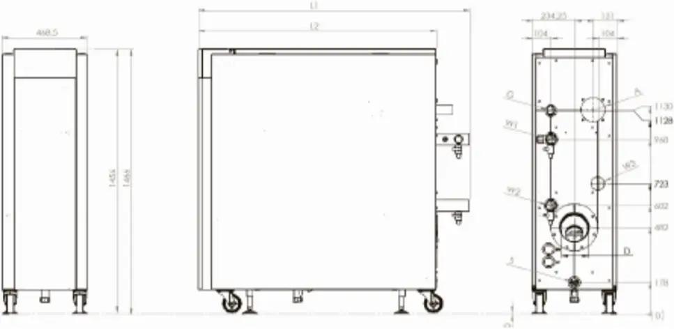
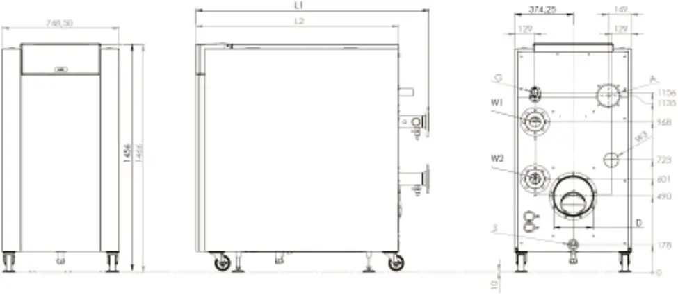
| SF61 EVO | SF62 EVO | SF63 EVO | SF64 EVO | SF65 EVO | SF66 EVO | SF67 EVO | ||
| L1 | mm | 1349 | 1499 | 1649 | 1348 | 1496 | 1646 | 1769 |
L2 | mm | 1165 | 1315 | 1465 | 1152 | 1302 | 1452 | 1602 |
| A | mm | Ø 130 | Ø 150 | |||||
G | mm | 1.1/2” | 2” | |||||
| D | mm | 150 | 200 | 250 | ||||
S | mm | 32 | ||||||
| W1-W2-W3 | mm | R2” | DN65 PN16 | |||||
Fig. 2 SF64 – SF65 – SF66 – SF67 EVO
3 Product Description
3.1 General
This document is meant to be used in addition to the SUPAflo EVO central heating boiler documentation, in case of having an (industrial) water heater. This document only contains the differences in construction and application to the central heating boiler version. General information on the boiler (transport, commissioning, maintenance, etc.) can be found in the central heating boiler documentation.
3.2 Technical description
Fig. 3
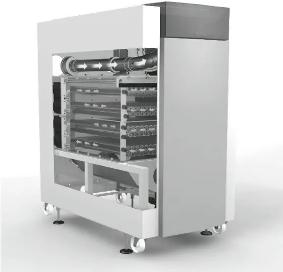
The (industrial) water heater is applicable for direct heating of sanitary hot water without using hydraulic separation (f.e. plate heat exchanger) in the system. All metallic materials in contact with water are made of stainless steel 1.4404. For the water heater, all components in contact with water are WRAS compliant.
3.3 Water quality
3.3.1 (Industrial) Water heater
As there is always fresh water flowing through the water heater, there are restrictions to the maximum flow temperature related to the hardness of the water. The following table indicates the maximum flow temperatures for different water hardness values. Not respecting these values can lead to damage of the heat exchanger.
For standard sanitary hot water systems the following applies:
Water hardness | Water hardness [°f] | Water hardness [ppm CaCO3] | Max temp setpoint [°C] |
| 2,8 – 8,4 | 5 – 15 | 50 – 150 | 75 |
8,4 – 11,2 | 15 – 20 | 150 – 200 | 65 |
| > 11,2 | > 20 | > 200 | water treatment |
pH-value should be between 7,0 – 9,5. Chloride level should not exceed 50mg/l.
For industrial hot water systems (higher flow temperatures) the following applies:
Water hardness | Water hardness [°f] | Water hardness [ppm CaCO3] | Max temp setpoint [°C] |
| 0 – 0,56 | 0 – 1 | 0 – 10 | 90 |
0,56 – 2,8 | 1 – 5 | 10 – 50 | 80 |
| > 2,8 | > 5 | > 50 | water treatment |
pH-value should be between 7,0 – 9,5. Chloride level should not exceed 50mg/l.
3.4 Hot water production (water heater only)
The following table shows the tapping volumes which can be achieved with a water heater, based on a cold water inlet temperature of 10ºC.
| Boiler type | Output at | flow 50°C | flow 60°C | flow 65°C | flow 70°C | flow 80°C | flow 90°C |
[kW] | [l/min] | [l/min] | [l/min] | [l/min] | [l/min] | [l/min] | |
| SF61 EVO | 142 | 51,1 | 40,8 | 37,1 | 34,0 | 29,2 | 25,5 |
| SF62 EVO | 190 | 68,3 | 54,7 | 49,7 | 45,5 | 39,0 | 34,2 |
| SF63 EVO | 238 | 85,6 | 68,5 | 62,2 | 57,1 | 48,9 | 42,8 |
| SF64 EVO | 286 | 102,8 | 82,3 | 74,8 | 68,6 | 58,8 | 51,4 |
| SF65 EVO | 381 | 137,0 | 109,6 | 99,6 | 91,3 | 78,3 | 68,5 |
| SF66 EVO | 477 | 171,5 | 137,2 | 124,7 | 114,3 | 98,0 | 85,8 |
| SF67 EVO | 540 | 194,2 | 155,3 | 141,2 | 129,4 | 111,0 | 97,1 |
3.5 Hydraulic connection
3.5.1 (Industrial) Water heater
The SUPAflo EVO (industrial) water heater must be installed in such a way, that a minimum water flow rate of 30% of the nominal flow rate can be assured at all times when the burner is switched on. The water heater can increase the water temperature by maximum 17K in a single cycle. This means that the water has to cycle through the water heater several times when f.e. cold water of 10ºC has to be heated up to 60ºC (3 times).
This is normally done by installing the water heater in combination with a buffer tank. The flow rate from the tank to the water heater and back can then be secured by the (primary) water heater pump.
The table below shows the nominal water flow data at a T of 17K, plus the pump data of the (optional) pump kit for each type of water heater.
| Boiler type | dT | Nominal flow | Boiler resistance | Pump type | Pump curve | Pump head | Available head |
[K] | [m3/h] | [kPa] | [-] | [-] | [kPa] | [kPa] | |
| SF61 EVO | 17 | 7,2 | 15 | UPS 32-80B | 3 | 37 | 22 |
| SF62 EVO | 9,5 | 37 | UPS 32-120FB | 3 | 62 | 25 | |
| SF63 EVO | 12,0 | 43 | UPS 40-120FB | 3 | 66 | 23 | |
| SF64 EVO | 14,4 | 16 | UPS 40-120FB | 3 | 34 | 18 | |
| SF65 EVO | 19,2 | 44 | UPS 50-120FB | 3 | 66 | 22 | |
| SF66 EVO | 24,0 | 47 | UPS 65-120FB | 3 | 61 | 14 | |
| SF67 EVO | 27,2 | 79 | UPS 65-180FB | 3 | 106 | 27 |
4 System Examples
4.1 System Example: Water heater with a SS300/500/800/1000-10-2.5″ single buffer vessel
The SUPAflo EVO connected to an Andrews SS300/500/800/1000-10-2.5” single buffer vessel with a separate cold feed and secondary return / drain ports directly into the buffer vessel. The buffer vessel also has individual flow and return ports for the water heater. The location and size of these ports will prevent cycling of the water heater and allow the heater to operate efficiently. The primary pump will constantly circulate water through the water heater and buffer vessel to allow the water heater to respond swiftly to any demand and provide a stable water temperature within the vessel and system. We recommend not to reduce the diameter of the pipe-work between the buffer vessel and water heater as this may reduce the design flow rate across the water heater. The Andrews SS300/500/800/1000-10-2.5” single buffer vessel has has an individual port in the vessel to fit a temperature and pressure relief valve direct in the top rear side of the vessel.
Fig. 5
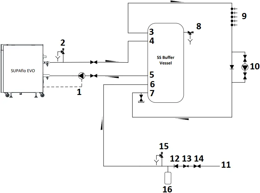
- Andrews Supplied Bronze Primary Pump
- Pressure Relief Valve 6 bar
- Hot Water Outlet
- Water Heater Flow
- Water Heater Return
- System cold Feed
- Drain & Secondary Return Port
- Temperature & Pressure Relief Valve 7 bar/95°C
- Hot Water Outlets
- Secondary Return Pump
- Mains Cold Water Supply
- Non-Return Valve
- Pressure Reducing Valve 3.5 bar
- Isolation Valve
- Pressure Relief Valve 6 bar
- Expansion Vessel 100L
4.2 System Example: Water heater with a SS300/500/800/1000-10-2.5″ single buffer vessel
MODEL | ||||
BUFFER-SS300-2.5” | BUFFER-SS500-2.5” | BUFFER-SS800-2.5” | BUFFER-SS1000-2.5” | |
| Height (mm) | 1685 | 1690 | 1840 | 2250 |
| Height to temperature and pressure relief valve port (mm) | 1400 | 1356 | 1457 | 1867 |
| Height to clean out and inspection hatch | 323 | 370 | 347 | 347 |
| Height to drain and secondary return connection (mm) | 70 | 70 | 100 | 100 |
| Height to water heater return connection (mm) | 473 | 520 | 497 | 497 |
| Height to cold feed connection (mm) | 323 | 370 | 347 | 347 |
| Height to water heater flow connection (mm) | 1250 | 1206 | 1307 | 1717 |
| Outside diameter (mm) | 620 | 770 | 950 | 950 |
| Cylinder diameter (mm) | 500 | 650 | 790 | 790 |
| Height to hot water flow connection (mm) | 1400 | 1356 | 1457 | 1867 |
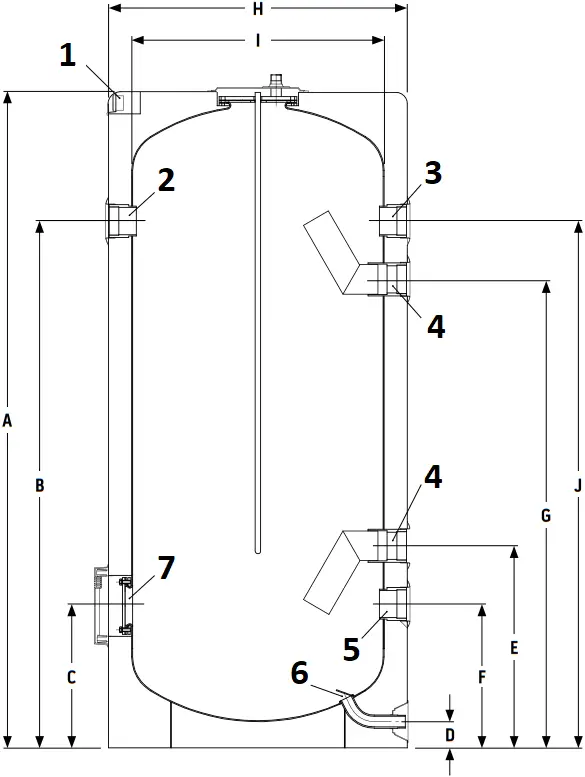
SECTION THROUGH VESSEL
- Temperature gauge
- Temperature and pressure relief valve port
- Hot water flow connection
- Water heater flow connection
- Cold feed connection
- Drain and secondary return connection
- Clean out and inspection hatch
Unvented Systems Kit
7820334: Unvented kit for SUPAflo EVO SF61 to SF63
Suitable for SF61 to SF63
- Pressure limiting valve 1 ½” 3.5 bar
- Non-return valve 1 ½”
- Expansion relief valve 6 bar 1¼” x 1½” DN32
- Expansion vessel 100L
- Temperature and pressure relief valve 2” DN40
- Straight tundish 1 ½” x 2”
- Straight tundish 2” x 2 ½”
7820335: Unvented kit for SUPAflo EVO SF64 to SF67
Suitable for SF64 to SF67
- Pressure limiting valve 2” 3.5 bar
- Non-return valve 2”
- Expansion relief valve 6 bar 1½” x 2” DN40
- Expansion Vessel 100L
- Temperature and pressure relief valve 2½” DN50
- Straight tundish 2” x 2 ½”
- Straight tundish 2 ½” x 3”
Draft D 10/10/22
SUPAflo EVO | TECHNICAL DATA SHEET

![]()


Register now to activate your warranty www.andrewswaterheaters.co.uk/register-a-warranty.
Please make sure you attach proof of purchase for your warranty to be monitored.
All descriptions and illustrations provided in this document have been carefully prepared but we reserve the right to make changes and improvements in our products which may affect the accuracy of the information contained in this leaflet. All goods are sold subjects to our standard Conditions of Sale which are available on request.
© Copyright
All technical and technological information contained in these technical instructions, as well as any drawings and technical descriptions supplied, remain our property and shall not be multiplied without our prior consent in writing. Subject to alterations.
Sales 0345 070 1055
Technical 0345 070 1057
Web andrewswaterheaters.co.uk
![]() linkedin.com/company/andrews-water-heaters
linkedin.com/company/andrews-water-heaters![]() @AndrewsWH
@AndrewsWH
Registered office address: Baxi Heating UK, Brooks House, Coventry Road, Warwick CV34 4LL
October 2022
Andrews. Built to perform.
 Complete heating and hot water solutions for your commercial projects.
![]()
![]()
![]()
![]()
![]()


