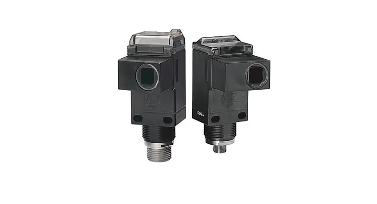
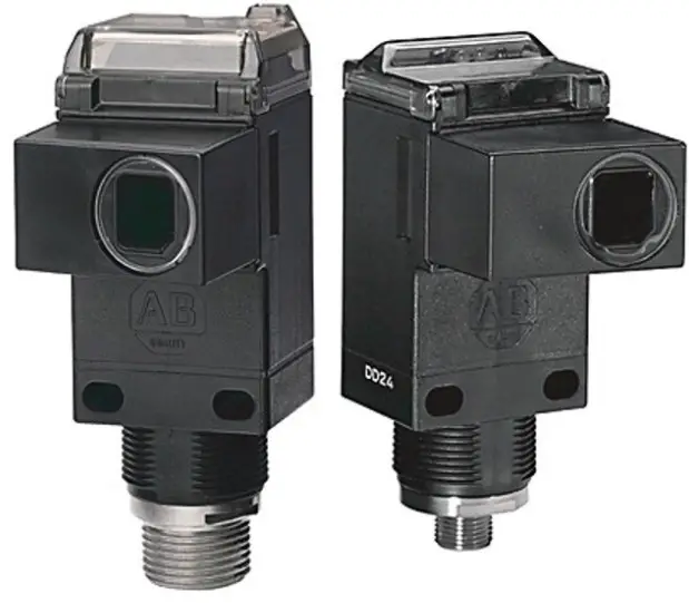
 Allen-Bradley PHOTOSWITCH Series 9000 On-Off and Timing Photoelectric Sensors
Specifications
Table 1 – All Photoelectric Sensors
| Specification | Retroreflective | Polarized Retroreflective | ClearSight | Standard Diffuse | Long Range Diffuse | Extended Range Diffuse | Transmitted Beam | Fiber-optic | |||
| Source (1) | Receiver | Plastic Visible Red | Glass Infrared | ||||||||
| Sensing distance | 9.1 m (30 ft) (2) | 4.9 m (16 ft) (2) | 1.2 m (4 ft) | 1.5 m (5 ft) | 3.0 m (10 ft) | 4.2 m (14 ft) | 61 m (200 ft) | 152 m (500 ft) | Depends on light source selected | Depends on fiber-optic selected | |
| 3.6 m (12 ft) (3) | 2 m (6.5 ft) (3) | ||||||||||
| 3 m (10 ft) (4) | 1 m (3 ft) (4) | ||||||||||
| Transmitting status indicator | Visible Red 660 nm | Visible Red 660 nm | Visible Red 660 nm | Infrared 880mn | Infrared 880mn | Infrared 880mn | Infrared 880mn | Infrared 880mn | — | Visible Red 660 nm | Infrared 880mn |
| Indicators | Yellow: Power Green: Output Red: Margin/SCP (5) | Yellow: Power Green: Output Red: Margin/SCP (5) | Yellow: Power Green: Output Red: Margin/SCP (5) | Yellow: Power Green: Output Red: Margin/SCP (5) | Yellow: Power Green: Output Red: Margin/SCP (5) | Yellow: Power Green: Output Red: Margin/SCP (5) | Yellow: Power Green: Output Red: Margin/SCP | Yellow: Power Green: Output Red: Margin/SCP | |||
| Field of view | 1.5° | 1.5° | 1.5° | 3.5° | 6.5° | 3.5° | 1.5° | 1.5° | 1.5° | Depends on fiber-optic selected | |
| Sensitivity adjustment | Single-turn Potentiometer | Single-turn Potentiometer | Single-turn Potentiometer | Single-turn Potentiometer | PSingle-turn r otentiomete | PSingle-turn r otentiomete | Single-turn Potentiometer | Single-turn Potentiometer | P Single-turn r otentiomete | Single-turn Potentiometer | Single-turn Potentiometer |
| Operating | -34…+70 °C | -34…+70 °C | -34…+70 °C | -34…+70 °C | -34…+70 °C | -34…+70 °C | -34…+70 °C | -34…+70 °C | -34…+70 °C | -34…+70 °C | -34…+70 °C |
| temperature | (-29…+158 °F)(6) | (-29…+158 °F)(6) | (-29…+158 °F)(6) | (-29…+158 °F)(6) | (-29…+158 °F)(6) | (-29…+158 °F) | (-29…+158 °F) | (-29…+158 °F) | (-29…+158 °F) | (-29…+158 °F) | (-29…+158 °F) |
| Relative humidity | 5…95% | 5…95% | 5…95% | 5…95% | 5…95% | 5…95% | 5…95% | 5…95% | 5…95% | 5…95% | 5…95% |
| Housing/lens material | Valox/acrylic | Valox/acrylic | Valox/acrylic | Valox/acrylic | Valox/acrylic | Valox/acrylic | Valox/acrylic | Valox/acrylic | Valox/acrylic | Valox/acrylic | Valox/acrylic |
| Operating | NEMA 3, 4X, 6P, | NEMA 3, 4X, 6P, | NEMA 3, 4X, 6P, 12, | NEMA 3, 4X, 6P, 12, | NEMA 3, 4X, 6P, 12, | NEMA 3, 4X, 6P, | NEMA 3, 4X, 6P, | NEMA 3, 4X, 6P, | NEMA 3, 4X, 6P, | NEMA 3, 4X, 6P, | NEMA 3, 4X, 6P, |
| environment | 12, 13, IP67 | 12, 13, IP67 | 13, IP67 | 13, IP67 | 13, IP67 | 12, 13, IP67 | 12, 13, IP67 | 12, 13, IP67 | 12, 13, IP67 | 12, 13, IP67 | 12, 13, IP67 |
| UL Listed | UL Listed | UL Listed C CSA certified ll E marked for a applicable directives | UL Listed | UL Listed | UL Listed | UL Listed CE marked CSA certified e directives for all applicabl | UL Listed CE ma CSA certified le rked for all applicab directives | ||||
| Approvals | CSA certified CE marked for all applicable | CSA certified CE marked for all applicable | CSA certified CE marked for all applicable | CSA certified CE marked for all applicable | CSA certified CE marked for all applicable | ||||||
| directives | directives | directives | directives | directives | |||||||
|
Protections | All Versions: False Pulse | All Versions: False Pulse | All Versions: False Pulse | All Versions: False Pulse | All Versions: False Pulse | All Versions: False Pulse | All Versions: False Pulse | All Versions: False Pulse | |||
| ouSolid-state : Shtput versions ort circuit and overload | Solid-state output versions: Short circuit and overload | Solid-state output versions: Short circuit and overload | ouSolid-state s: Shtput version ort circuit and overload | ouSolid-state : Shtput versions ort circuit and overload | ouSolid-state : Shtput versions ort circuit and overload | Solid-state output versions: Short circuit and overload | Solid-state output versions: Short circuit and overload | ||||
| DC versions: Reverse polarity | DC versions: Reverse polarity | DC versions: Reverse polarity | DC versions: Reverse polarity | DC versions: Reverse polarity | DC versions: Reverse polarity | DC versions: Reverse polarity | DC versions: Reverse polarity | ||||
| Vibration | 1 10…55 Hz .) mm (0.04 in M amplitude ds eets or excee IEC 947-5-2 | 1 10…55 Hz .) mm (0.04 in amplitude Meets or exceeds IEC 947-5-2 | 1 10…55 Hz .) mm (0.04 in M amplitude s eets or exceed IEC 947-5-2 | 1 10…55 Hz .) mm (0.04 in M amplitude eets or exceeds IEC 947-5-2 | 1 10…55 Hz .) mm (0.04 in M amplitude ds eets or excee IEC 947-5-2 | 1 10…55 Hz ) mm (0.04 in. M amplitude eets or exceeds IEC 947-5-2 | 1 mm 10…55 Hz Meets o(0.04 in.) amplitude-2 r exceeds IEC 947-5 | 1 mm (010…55 Hz litude Meets or .04 in.) amp947-5-2 exceeds IEC | |||
| Shock | 30G with 1 ms pulse duration Meets or exceeds IEC 947-5-2 | 30G with 1 ms pulse duration Meets or exceeds IEC 947-5-2 | 30G with 1 ms pulse duration Meets or exceeds IEC 947-5-2 | 30G with 1 ms pulse duration Meets or exceeds IEC 947-5-2 | 30G with 1 ms pulse duration Meets or exceeds IEC 947-5-2 | 30G with 1 ms pulse duration Meets or exceeds IEC 947-5-2 | 30G with 1 ms pulse duration Meets or exceeds IEC 947-5-2 | 30G with 1 ms pulse duration Meets or exceeds IEC 947-5-2 | |||
- Transmitted beam source rated 10…264V AC/DC.
- 78 mm (3 in.) reflector
- 32 mm (1.25 in.) reflector
- 16 mm (0.625 in.) reflector
- Red: Illuminates when margin ≤0.5x (no target) and ≥2.5x (target).
- Except models with solid-state and relay output (see page 8).
Table 2 – 10…30V DC Photoelectric Sensors — NPN and PNP
| Specification | Retroreflective | Polarized Retroreflective | ClearSight | Standard Diffuse | Long Range Diffuse | Extended Range Diffuse | Transmitted Beam | Fiber-optic | |||
| Source (1) | Receiver | Plastic Visible Red | Glass Infrared | ||||||||
| 2 Cat. No. 3m (9.84 ft) 00V cable | 42GxU-9000 (2) | 42GxU-9200 | 42GxC-9200 (2) | 42GxP-9000 (3) | 42GRP-9040 | 42GRP-9070 | 42GRL-9000 | 42GRL-9040 | 42GxR-9000 (2) | 42GxF-9100 (2) | 42GxF-9000 (2) |
| 4- Cat. No.cro pin DC mi QD | 42GxU-9000-QD | 42GxU-9200-QD | 42GxC-9200-QD | 42GxP-9000-QD | 42GRP-9040-QD | 42GRP-9070-QD | 42GRL-9000-QD | 42GRL-9040-QD | 42GxR-9000-QD | 42GxF-9100-QD | 42GxF-9000-QD |
| 4- Cat. No. QD pin micro | 42GxU-9000-QD1 | 42GxU-9200-QD1 | 42GxC-9200-QD1 | 42GxP-9000-QD1 | 42GRP-9040-QD1 | 42GRP-9070-QD1 | 42GRL-9002-QD | 42GRL-9042-QD | 42GxR-9000-QD1 | 42GxF-9100-QD1 | 42GxF-9000-QD1 |
| Supply current | 30 mA | 30 mA | 30 mA | 30 mA | 30 mA | 50 mA | 15 mA | 15 mA | 25 mA | 30 mA | 30 mA |
| Specification | Retroreflective | Polarized Retroreflective | ClearSight | Standard Diffuse | Long Range Diffuse | Extended Range Diffuse | Transmitted Beam | Fiber-optic | |||
| Source (1) | Receiver | Plastic Visible Red | Glass Infrared | ||||||||
| Output energized | Light/dark selectable | Light/dark selectable | Light/dark selectable | Light/dark selectable | Light/dark selectable | Light/dark selectable | — | — | Light/dark selectable | Light/dark selectable | Light/dark selectable |
| Load current | 250 mA (4) | 250 mA (4) | 250 mA (4) | 250 mA (4) | 250 mA (4) | 250 mA | — | — | 250 mA | 250 mA | 250 mA |
| Leakage current | 10 µA | 10 µA | 10 µA | 10 µA | 10 µA | 10 µA | — | — | 10 µA | 10 µA | 10 µA |
| Power consumption | 4VA max | 4VA max | 4VA max | 4VA max | 4VA max | 4VA max | 4VA max | 4VA max | 4VA max | 4VA max | 4VA max |
| Response time | 2 ms (5) | 2 ms (5) | 2 ms (5) | 2 ms (5) | 2 ms | 2 ms | — | — | 5 ms | 2 ms | |
- Transmitted beam source rated 10…264V AC/DC.
- x = R: On/Off, or T: timer version.
- x = L: Linear sense potentiometer, S: Teachable version, R: Nonlinear sense potentiometer, or T: Timer version.
- 100 mA for 42GSP, 9000, and 42GLP-9000 models.
- 5 ms for timer versions
Table 3 – 10…55V DC/20…40V AC Photoelectric Sensors — SPDT EM Relay
| Specification | Retroreflective | Polarized Retroreflective | ClearSight | Standard Diffuse | Long Range Diffuse | Extended Range Diffuse | Transmitted Beam | Fiber-optic | ||
| Source (1) | Receiver | Plastic Visible Red | Glass Infrared | |||||||
| 2 Cat. No. 3m (9.84 ft) 00V cable | 42GxU-9001 (2) | 42GxU-9201 (2) | — | 42GxP-9001 (2) | 42GRP-9041 | — | — | 42GRR-9001 | 42GxF-9101 (2) | 42GxF-9001 (2) |
| 5-pCat. No. QD in micro | 42GxU-9001-QD | 42GxU-9201-QD | — | 42GxP-9001-QD | 42GRP-9041-QD | — | — | 42GRR-9001-QD | 42GxF-9101-QD | 42GxF-9001-QD |
| Supply current | 40 mA | 40 mA | — | 40 mA | 40 mA | — | — | 35 mA | 40 mA | |
| Output energized | Light/dark selectable | Light/dark selectable | — | Light/dark selectable | Light/dark selectable | — | — | Light/dark selectable | Light/dark selectable | |
| Load current | 2A/132V AC 1A/264V AC 1A/150V DC | 2A/132V AC 1A/264V AC 1A/150V DC | — | 2A/132V AC 1A/264V AC 1A/150V DC | 2A/132V AC 1A/264V AC 1A/150V DC | — | — | 2A/132V AC 1A/264V AC 1A/150V DC | 2A/132V AC 1A/264V AC 1A/150V DC | |
| Leakage current | — | — | — | — | — | — | — | — | ||
| Power consumption | 2.2 watts/ 1.6VA max | 2.2 watts/ 1.6VA max | — | 2.2 watts/ 1.6VA max | 2.2 watts/ 1.6VA max | — | — | 3VA max | ||
| Response time | 15 ms (3) | 15 ms (3) | — | 15 ms (3) | 15 ms | — | — | 23 ms | 15 ms | |
- Transmitted beam source rated 10…264V AC/DC
- x = R: On/Off, or T: timer version.
- 18 ms for timer versions.
Table 4 – 70…264V DC/60…264V AC Photoelectric Sensors — SPDT EM Relay
| Specification | Retroreflective | Polarized Retroreflective | ClearSight | Standard Diffuse | Long Range Diffuse | Extended Range Diffuse | Transmitted Beam | Fiber-optic | ||
| Source (1) | Receiver | Plastic Visible Red | Glass Infrared | |||||||
| 2 Cat. No. 3m (9.84 ft) 00V cable | 42GxU-9002 (2) | 42GxU-9202 (2) | 42GxC-9202 (2) | 42GxP-9002 (2) | 42GRP-9042 | 42GRP-9072 | — | 42GxR-9002 (2) | 42GxF-9102 (2) | 42GxF-9002 (2) |
| 5-pCat. No. QD in micro | 42GxU-9002-QD | 42GxU-9202-QD | 42GxC-9202-QD | 42GxP-9002-QD | 42GRP-9042-QD | 42GRP-9072-QD | — | 42GxR-9002-QD | 42GxF-9102-QD | 42GxF-9002-QD |
| Supply current | 15 mA | 15 mA | 15 mA | 15 mA | 15 mA | 15 mA | — | 10 mA | 15 mA | |
| Output energized | Light/dark selectable | Light/dark selectable | Light/dark selectable | Light/dark selectable | Light/dark selectable | Light/dark selectable | — | Light/dark selectable | Light/dark selectable | |
| Load current | 2A/132V AC 1A/264V AC 1A/150V DC | 2A/132V AC 1A/264V AC 1A/150V DC | — | 2A/132V AC 1A/264V AC 1A/150V DC | 2A/132V AC 1A/264V AC 1A/150V DC | — | — | 2A/132V AC 1A/264V AC 1A/150V DC | 2A/132V AC 1A/264V AC 1A/150V DC | |
| Leakage current | — | — | — | — | — | — | — | — | ||
| Power consumption | 4 watts/ 4VA max | 4 watts/ 4VA max | 4 watts/ 4VA max | 4 watts/ 4VA max | 4 watts/ 4VA max | 4VA max | — | 4VA max | 4VA max | |
| Response time | 15 ms (3) | 15 ms (3) | 15 ms (3) | 15 ms (3) | 15 ms | 15 ms | — | 23 ms | 15 ms | |
- Transmitted beam source rated 10…264V AC/DC.
- x = R: On/Off, or T: timer version
- 18 ms for timer versions.
Table 5 – 70…264V AC/DC Photoelectric Sensors — Solid-state Isolated N.O.
| Specification | Retroreflective | Polarized Retroreflective | ClearSight | Standard Diffuse | Long Range Diffuse | Extended Range Diffuse | Transmitted Beam | Fiber-optic | |||
| Source (1) | Receiver | Plastic Visible Red | Glass Infrared | ||||||||
| 2 Cat. No. 3m (9.84 ft) 00V cable | 42GxU-9003 (2) | 42GxU-9203 (2) | 42GxC-9203 (2) | 42GxP-9003 (2) | 42GRP-9043 | — | — | 42GRR-9003 | 42GxF-9103 (2) | 42GxF-9003 (2) | |
| 4- Cat. No. QD pin micro | 42GxU-9003-QD | 42GxU-9203-QD | 42GxC-9203-QD | 42GxP-9003-QD | 42GRP-9043-QD | — | — | 42GRR-9003-QD | 42GxF-9103-QD | 42GxF-9003-QD | |
| 4- Cat. No.cro pin AC mi QD | 42GxU-9003-QD1 | 42GxU-9203-QD1 | 42GxC-9203-QD1 | 42GxP-9003-QD1 | 42GRP-9043-QD1 | — | — | 42GRL-9043-QD1 | 42GRR-9003-QD1 | 42GxF-9103-QD1 | 42GxF-9003-QD1 |
| Supply current | 15 mA | 15 mA | 15 mA | 15 mA | 15 mA | — | — | 15 mA | 15 mA | 15 mA | |
| Specification | Retroreflective | Polarized Retroreflective | ClearSight | Standard Diffuse | Long Range Diffuse | Extended Range Diffuse | Transmitted Beam | Fiber-optic | |||
| Source (1) | Receiver | Plastic Visible Red | Glass Infrared | ||||||||
| Output energized | Light/dark selectable | Light/dark selectable | Light/dark selectable | Light/dark selectable | Light/dark selectable | — | — | Light/dark selectable | Light/dark selectable | ||
| Load current | 300 mA | 300 mA | 300 mA | 300 mA | 300 mA | — | — | 300 mA | 300 mA | ||
| Leakage current | 1 mA at 264V AC/DC | 1 mA at 264V AC/DC | 1 mA at 264V AC/DC | 1 mA at 264V AC/DC | 1 mA at 264V AC/DC | — | — | 1 mA at 264V AC/DC | 1 mA at 264V AC/DC | ||
| Power consumption | 4 watts/ 4VA max | 4 watts/ 4VA max | 4 watts/ 4VA max | 4 watts/ 4VA max | 4 watts/ 4VA max | — | — | 4VA max | 4VA max | 4VA max | |
| Response time | 2 ms (3) | 2 ms (3) | 2 ms (3) | 2 ms (3) | 2 ms | — | — | 15 ms | 2 ms | ||
- Transmitted beam source rated 10…264V AC/DC.
- x = R: On/Off, or T: timer version.
- 5 ms for timer versions.
| Conductor Size (AWG) | Max Current/Min Voltage of Overcurrent Protection |
| 20 | 5 A/300V |
| 22 | 3 A/300V |
| 24 | 2 A/300V |
| 26 | 1 A/300V |
| 28 | 0.8 A/300V |
| 30 | 0.5 A/300V |
Wiring Diagrams
Shows all models except transmitted beam source.
Figure 1 – Cable Model: 9xx0
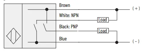
Figure 2 – 4-pin DC Micro QD Model: 9xx0-QD
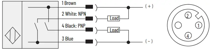
Figure 3 – 4-pin DC Mini QD Model: 9xx0-QD1
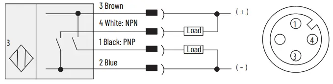
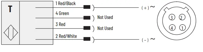
Figure 4 – Cable Model: 9xx3
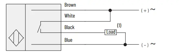
- Load can be placed on either black or white wire to create sourcing or sinking respectively.
Figure 5 – AC/DC Mini QD Model: 9xx3-QD
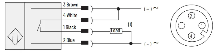
- Load can be placed on either black or white wire to create sourcing or sinking respectively
Figure 6 – AC/DC Micro QD Model: 9xx3-QD11
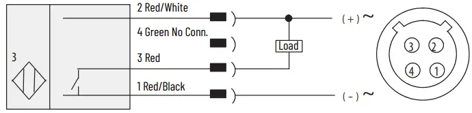
Figure 7 – Cable Model: 9xx1, 9xx2
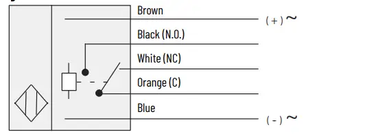
Figure 8 – 5-pin AC/DC Mini QD Model: 9xx1-QD, 9xx2-QD
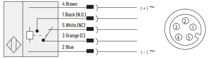
Figure 9 – Transmitted Beam Source Cable Model: 42GRL-90x
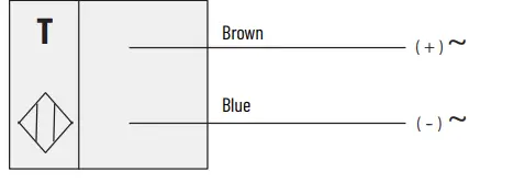
Figure 10 – AC/DC Mini QD Model: 42GRL-90×2-QD
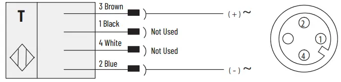
Figure 11 – DC Micro QD Model: 42GRL-90×0-QD
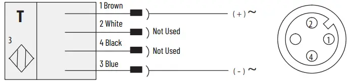
Figure 12 – 4-pin DC Micro QD Model: 42GRL-90×3-QD1
Typical Response Curves
Figure 13 – Retroreflective [mm (in.)]
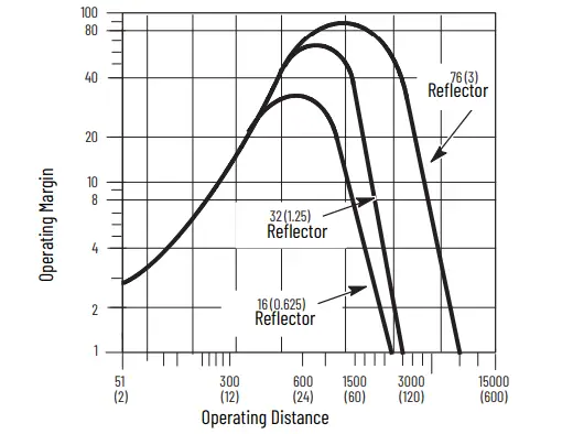
Figure 14 – Polarized Retroreflective [mm (in.)]
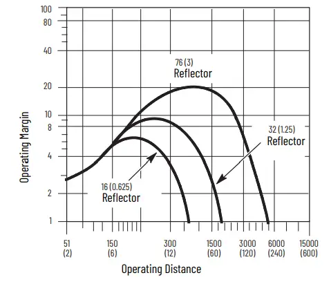
Figure 15 – ClearSight Clear Object Detector [mm (in.)]
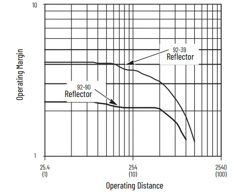
Figure 16 – Standard Diffuse [mm (in.)]
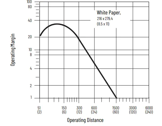
Figure 17 – Long Range Diffuse
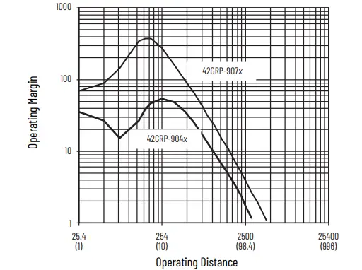
Figure 18 – Transmitted Beam, 61 m (200 ft), 152 m (500 ft) Light Source [mm (in.)]
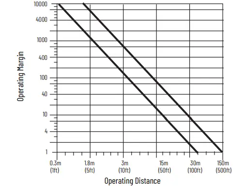
Figure 19 – Visible Red Fiber-optic Standard Diffuse
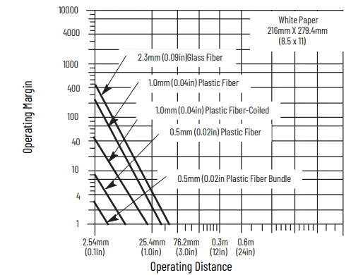
Figure 20 – Visible Red Fiber-optic Transmitted Beam
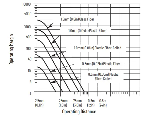
Figure 21 – Visible Red Fiber-optic Retroreflective
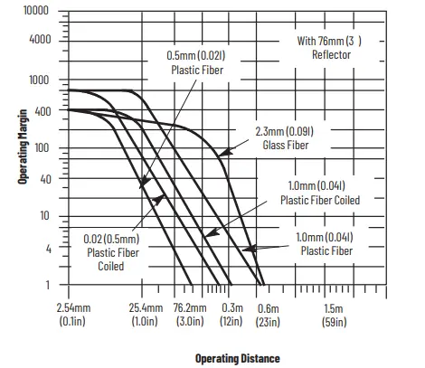
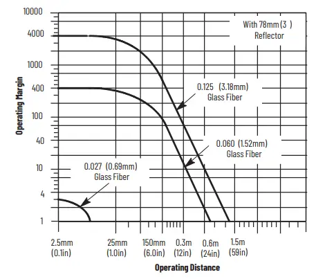
Figure 22 – Infrared Fiber-optic Standard Diffuse
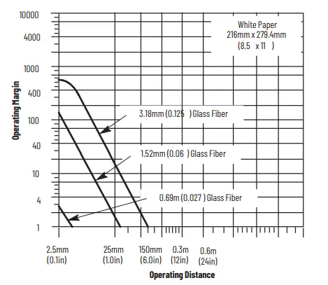
Figure 23 – Infrared Fiber-optic Transmitted Beam
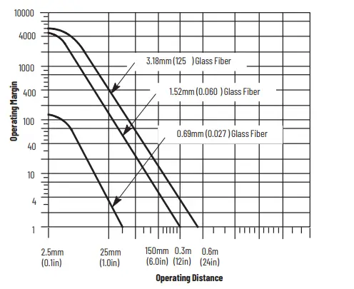
Figure 24 – Infrared Fiber-optic Retroreflective
Approximate Dimensions
Figure 25 – All Cable Versions Except Fiber-optic [mm (in.)]
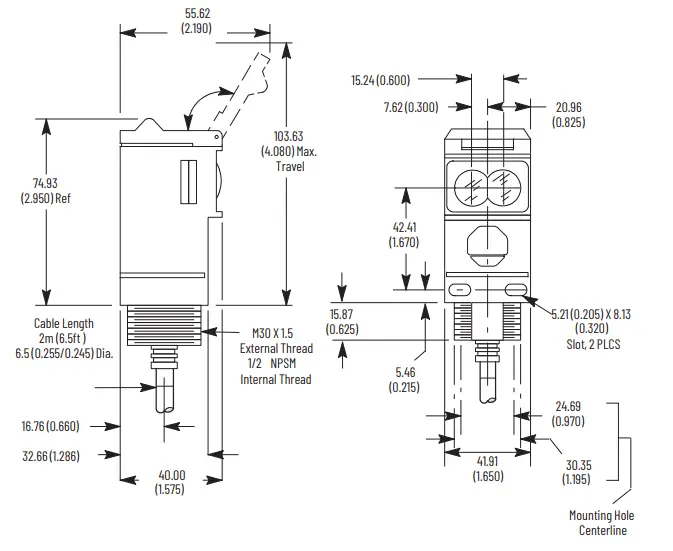
Figure 26 – Fiber-optic [mm (in.)]
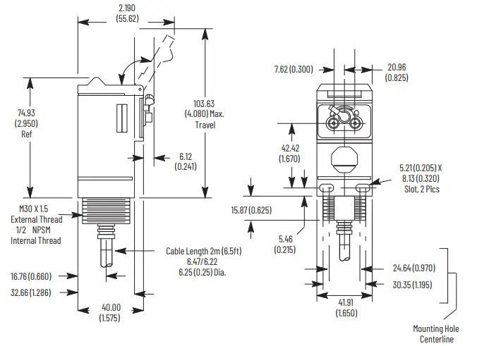
Figure 27 – ClearSight 9000 Versions [mm (in.)]
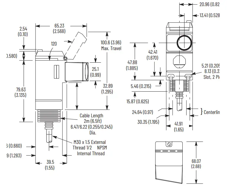
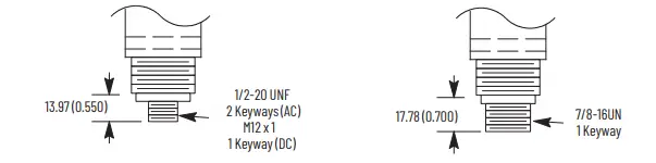
Figure 28 – Connector Version [mm (in.)]
Accessories
Figure 29 – Swivel/tilt Mounting Assembly #60-2439 [mm (in.)]
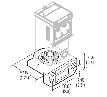
Figure 30 – Swivel/tilt Mounting Assembly #60-2681 for ClearSight 9000 [mm (in.)]
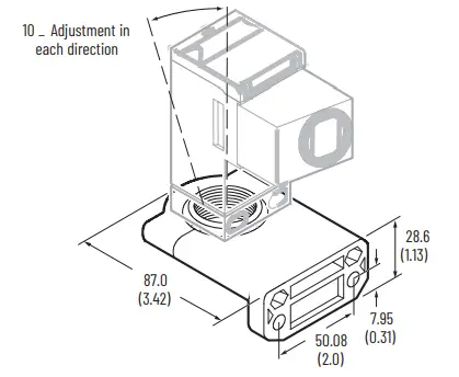
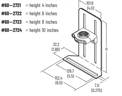
Figure 31 – Vertical Height Adjustment Brackets [mm (in.)]
Operational Notes
Figure 32 – Ambient Temperature Ratings
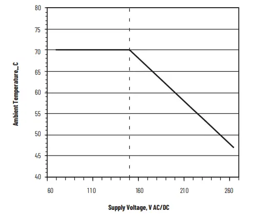
All models of the Series 9000 photoelectric sensor, except for models with the solid-state output (catalog number 42Gxx-9xx3) and the EM-relay output (catalog number 42Gxx-9xx2), have a maximum operating temperature of 70 °C (158 °F). The maximum operating temperature of models 42Gxx-9xx3 and 42Gxx-9xx2 can be determined from Figure 32. The temperature is based on the supply voltage that is fed to the photoelectric sensor. For example, if the operating voltage is 120V AC, the maximum operating temperature would be 70 °C (158 °F). An operating voltage of 220V AC would limit the ambient operating temperature to 55 °C (131 °F). Operation of the photoelectric sensor at ambient temperatures that exceed these limits could result in sensor failure.
Mounting and Wiring
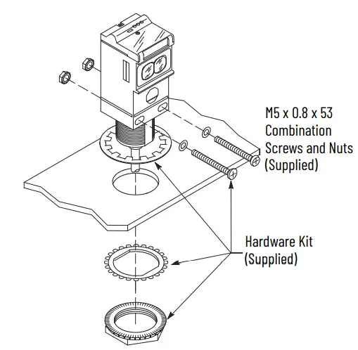
Securely mount the photoelectric sensor on a firm, stable surface or support. A mount that is subject to excessive vibration or shifts can cause intermittent operation. Rockwell Automation offers a wide variety of fixed and adjustable mounting brackets and reflectors and quick disconnect cables. The photoelectric sensor is supplied with the hardware kit #129-130, which contains a plastic mounting nut, lock washer, and two M5 x 0.8 x 53 screws and nuts. Once securely mounted, the photoelectric sensor can be wired as indicated in the wiring diagrams
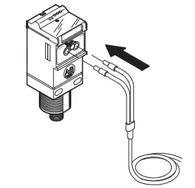
Install Fiber-Optic Cables (42GxF-9xxx models only)
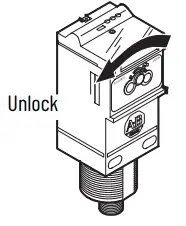
- Confirm that the fiber-optic cable locking lever on the photoelectric sensor is in the unlocked position.

- Insert the fiber-optic cable until the internal clip mechanism is engaged

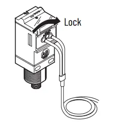
- Rotate the locking lever to the lock position.
- Mount the fiber-optic cable sensing tip end as appropriate.
Wiring the Photoelectric Sensor
The Series 9000 photoelectric sensor is available in one of three different connection types as identified in Specifications on page 1. We recommend the use of the 889 Series of cordsets and patchcords on the quick disconnect models. All external wiring must conform to the National Electrical Code and all applicable local codes.
Align and Configure the Photoelectric Sensor
All Models Except 42GSP-9000
User Interface
To gain access to the user interface panel, use a screwdriver to open the top cover of the photoelectric sensor. This panel contains a single-turn sensitivity adjustment knob, a two-position mode selector switch, and three status indicators.Use the screwdriver to increase (clockwise) or decrease (counterclockwise) the sensitivity to meet the application requirements. The factory default setting for all versions is maximum sensitivity.
IMPORTANT Damage to the single-turn sensitivity adjustment knob occurs if it is turned beyond the in/max steps. After initial photoelectric sensor configuration, confirm that the user interface cover is closed tightly to maintain specified environmental ratings.
Figure 33 – 42GRx Top View Detail
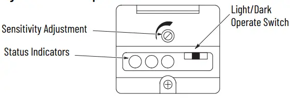
The Series 9000 photoelectric sensor also contains a two-position selector switch. This switch is used to select either Light- or Dark-operate mode of the photoelectric sensor. In Light-operate mode, the photoelectric sensor output turns on when light is being reflected back to it (reflector for retroreflective, source for transmitted beam, or target for diffuse). In Dark-operate mode, the photoelectric sensor output turns off when no light is being reflected back to it. See Table 6.
Photoelectric Sensor Alignment
The red status indicator is an alignment aid, which indicates that a margin of 2.5X, is reached. At this margin, the photoelectric sensor is receiving at least 2.5 times the signal strength back from the target that triggers an output signal. A higher margin is recommended to help overcome any deteriorating environmental conditions, such as dust buildup on the lens of the photoelectric sensor. When aligning the photoelectric sensor, the best performance is obtained if the margin indicator illuminates with the target in place. We recommend leaving the sensitivity at the default maximum setting and change the setting only when necessary.
Table 6 – Status Indicators
Transmitted Beam Versions
- Visually align the emitter and receiver units (fibers) until the green output status indicator turns on (with Light-operate mode) or turns off (with Darkoperate mode).
- To be certain that the beam is centered, sweep the emitter or receiver in the horizontal and vertical plane and determine at what position the output indicator turns on and then turns off. Set the sensor (or fiber-optics) midway between both positions. The red margin status indicator is on when the beam is unbroken.
Retroreflective and Polarized Retroreflective Versions
- Visually align the sensor (or fiber-optic cable) on the reflector until the green output status indicator turns on (with Light-operate mode) or turns off (with Dark-operate mode). Also verify that the red margin status indicator is on.
- To be certain that the beam is centered, sweep the sensor in the horizontal and vertical plane and determine at what position the output indicator goes turns and then turns off. Set the sensor (or fiber-optics) midway between both positions.
- Break the beam with the object to be detected and check if the output status indicator turns on (Dark-operate mode). If necessary, turn down the sensitivity adjustment until the output status indicator turns on. Remove the object to restore the light beam and check if the output status indicator turns off again and that the red margin status indicator turns on. If the status indicates do not change, increase the size of the reflector or decrease the distance between the reflector and the photoelectric sensor.
Diffuse Mode
- Visually align the sensor (or fiber-optic cable) on the object until the green output status indicator turns on (with Light-operate mode) or turns off(Dark-operate mode).
- To be certain that the beam is centered, sweep the sensor in the horizontal and vertical plane and determine at what position the output indicator goes on and then goes off. Set the sensor (or fiber-optics)midway between both positions.
- Remove the object in front of the sensor and eliminate any existing background signals by turning down the sensitivity adjustment. Replace the object and verify that the output status indicator turns on and that the margin status indicator is on. If the sensor continues to pick up background reflections, you must either eliminate those reflections (paint with a nonreflective color), or replace the photoelectric sensor with a background suppression, a sharp cutoff diffuse, or a Retroreflective Sensing mode version.
42GSP- 9000 Models
User Interface
Use a screwdriver to open the top cover of the photoelectric sensor to gain access
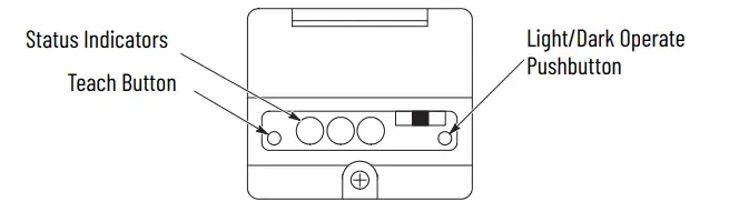
to the user interface panel. This panel contains two push buttons and three status indicators. The left push button puts the photoelectric sensor into Teach mode while the right-hand button is for light/dark operate selection.
Teach Mode
The Teach mode of the 42GSP-9000 photoelectric sensor enables the it to learn both the light and dark conditions that are presented to it and to automatically adjust sensitivity to the optimal level for the application. This mode replaces the sensitivity adjustment knob of a conventional photoelectric sensor. With the photoelectric sensor pointed at the light condition (target), momentarily press the Teach button until the red status indicator turns on. After 3 seconds, this status indicator flashes, which indicates that it is ready to receive the dark condition (background). The red status indicator momentarily remains steady, then turns off, which indicates that the teach operation was successful. The 42GSP-9000 photoelectric sensor also contains a two-position push button. This button selects either Light- or Dark-operate mode of the photoelectric sensor. In Light-operate mode, the photoelectric sensor output turns on when light is reflected back to it (indicated by the output status indicator being on). In Dark-operate mode, the photoelectric sensor output turns on when no light is reflected back to it. Table 34 describes the function of the three status indicators.
Figure 34 – Status Indicators
Figure 35 – 42GSP Top View Detail
42GTx Models
Some versions of the Series 9000 photoelectric sensor also contain a four-bank
DIP switch (S1…S4) and two rotary knobs (R2 and R3). These devices are used to
configure internal on, off, and one-shot time delays making it possible to provide some degree of local control in an application.
Figure 36 – Timing Photoelectric Sensors Top View Detail
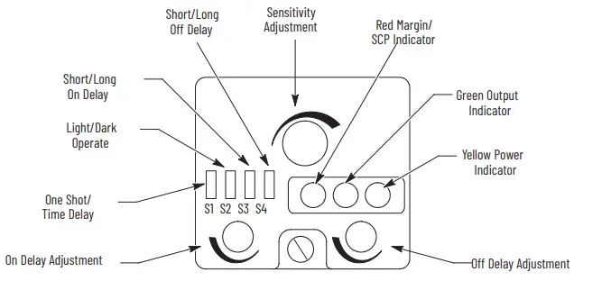
The timers are nonretriggerable. The timing can be set for short (0…1.5 s) or long (0…15 s) duration using the DIP switches and adjusted via the two 15-turn rotary knobs. See Figure 37 and Figure 38 to configure these timers.
IMPORTANT After initial photoelectric sensor configuration, confirm that the user interface cover is closed tightly to maintain specified environmental ratings.
42GRL Models
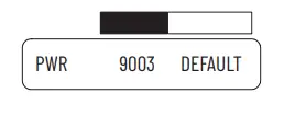
For the 9003 model photoelectric sensors, the switch must be pushed to the left, towards 9003. For all other models, the switch must be pushed to the right, towards default.
Figure 37 – Typical ON/OFF Timing Diffuse (Light-operate) Nonretriggerable
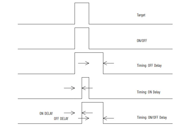
Figure 38 – Typical One-Shot Timing Diffuse (Light-operate) Nonretriggerable
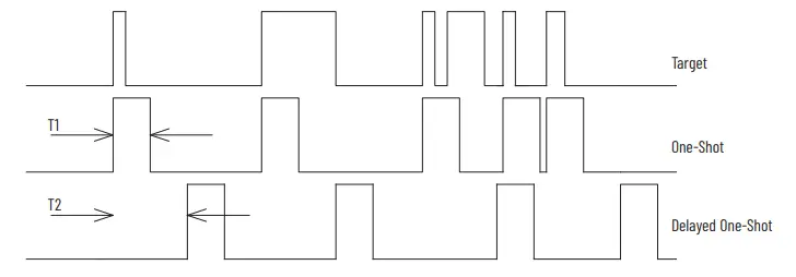
- T1 is adjusted via the off delay potentiometer with either a long (0…15 s) or short (0…1.5 s) DIP switch setting.
- T2 is adjusted via the on delay potentiometer with either a long (0…15 s) or short (0…1.5 s) DIP switch setting
Application Example
Product travels down a conveyor. If the product is a white box, a kicker located 3 seconds down the conveyor activates to push the box down another conveyor. The kicker must extend and retract for 1 second. The sensor is a 42GTP-9000 photoelectric sensor. In this application, an on and off delay are required. Set the first DIP switch (S1) to TD position. Switch (S2) is set to LT position. Switch (S3) isset to L position for a 3 second delay. Switch (S4) is set to the S position. The delay is adjusted by turning the on delay pot clockwise until the proper delay time is set. The off delay pot is turned clockwise so to set the 1 second off delay.
Waste Electrical and Electronic Equipment (WEEE)
At the end of life, this equipment should be collected separately from any unsorted municipal waste. Rockwell Automation maintains current product environmental compliance information on its website at rok.auto/pec. Your comments help us serve your documentation needs better. If you have any suggestions on how to improve our content, complete the form at rok.auto/docfeedback. For technical support, visit rok.auto/support. Allen-Bradley, expanding human possibility, PHOTOSWITCH, and Rockwell Automation are trademarks of Rockwell Automation, Inc. Trademarks not belonging to Rockwell Automation are property of their respective companies. Publication 42G-IN003B-EN-P – October 2021 | Supersedes Publication 42G-IN003A-EN-P – August 2014 Copyright © 2021 Rockwell Automation, Inc. All rights reserved. Printed in the U.S.A.


