Rvs-127 Blind Spot Sensor System Instruction Manual

Rvs-127 Blind Spot Sensor System Instruction Manual

RVS_127_logo

RVS-127 Blind Spot Sensor System

RVS-127-Blind-Spot-Sensor-System-Product-image 

ASSEMBLY INSTRUCTIONS

RVS-127-Blind-Spot-Sensor-System-01

RVS-127-Blind-Spot-Sensor-System-02

RVS-127-Blind-Spot-Sensor-System-03

RVS-127-Blind-Spot-Sensor-System-04

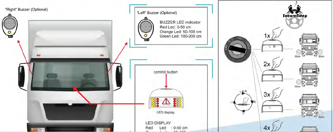
  • AUX2: 500 mA gnu output will be activated when system gives buzzer alert during ignition on. It can be used to trigger camera
    system monitor.
  • Brake wire is for models without gaps
  • AUX1: 500 mend output will be activated when Secure Sleep system detect movement around the vehicle. it should be connected to the vehicle parking lights with relay’.

RVS-127-Blind-Spot-Sensor-System-05

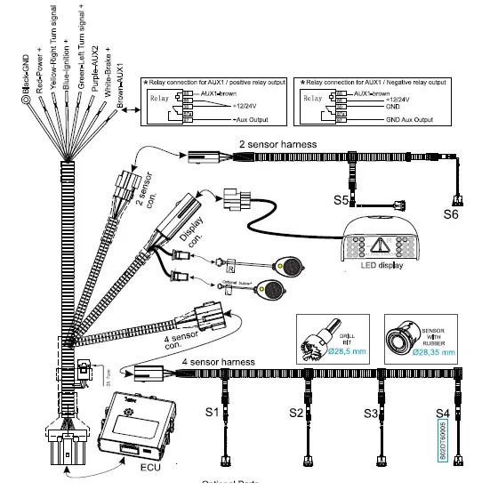
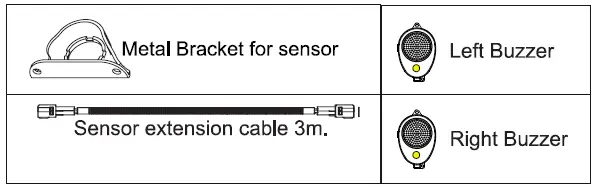
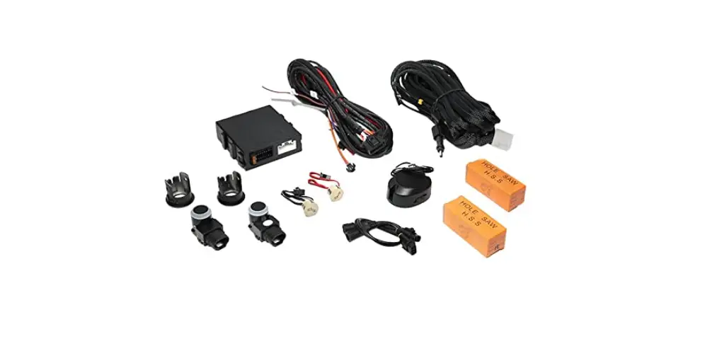
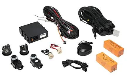
Standard set includes

  • 4/6 pcs sensor with rubber
  • 1 pc ECU
  • 2/3 sets wiring harness
  • 1 pc LED display + GPS
  • 1 pc 24V relay
  • 1 pc Drill Bit 028,5

RVS-127-Blind-Spot-Sensor-System-06

RVS-127-Blind-Spot-Sensor-System-07

Documents / Resouces

Download manual
Here you can download full pdf version of manual, it may contain additional safety instructions, warranty information, FCC rules, etc.


Related Manuals