
Rydeen BSS-ONE Single Sensor Blind Spot Detector
Product Information
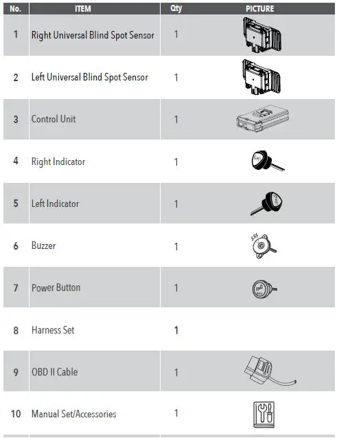
The Blind Spot Detection System is designed for passenger vehicles and includes a control unit, two universal blind spot sensors (one for the left and one for the right), a right indicator, a left indicator, a buzzer, a power button, a harness set, an OBD II cable, and a manual set with accessories.
System Specifications
- Operating Temperature: N/A
- Storage Temperature: N/A
- Environmental Protection Level: Level I
- Input Voltage Range: N/A
- Current Consumption: 500mA @ 12V ; 6.0W
- Alarm Level: Level I (LED On – Constant) Level II (LED Flash + Buzzer On)
- Accuracy of Alarm: Vehicle >99%
- Specifications: ISO 17387/IS0 16750
- Radiation Regulations: FCC / NCC / VSCC
- Buzzer: 75dB
- Warning Indicator: 5V Drive, A-Pillar
System Layout
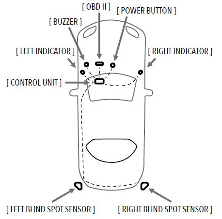
The system layout includes an OBD II port, a power button, a buzzer, left and right indicators, a control unit, and left and right blind spot sensors.
Product Usage Instructions
WARNING
- Wear proper protective gear
- Deburr edges and use grommets
- Use appropriate torque to fasten (lb-ft)
- Do not pull the connectors or harness with excessive force
- Fasten all connectors and terminals securely
- Stress relieve harnesses and secure them properly
Installation
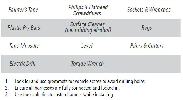
Tools Required
- Painter’s Tape
- Plastic Pry Bars
- Philips & Flathead Screwdrivers
- Surface Cleaner (i.e. rubbing alcohol)
- Tape Measure
- Level
- Sockets & Wrenches
- Rags
- Pliers & Cutters
- Electric Drill
- Torque Wrench
Installation Steps
- Look for and use grommets for vehicle access to avoid drilling holes.
- Ensure all harnesses are fully connected and locked in.
- Use the cable ties to fasten the harness while installing.
Note: The Blind Spot Detection System installation requires professional expertise. It is recommended that you seek assistance from a certified mechanic or technician for proper installation.
WARNING
- THE UNIVERSAL BLIND SPOT DETECTION SYSTEM DOES NOT REPLACE ANY FUNCTIONS DRIVERS SHALL ORDINARILY PERFORM IN DRIVING A MOTOR VEHICLE, NOR DOES IT DECREASE THE NEED FOR DRIVERS TO STAY VIGILANT AND ALERT IN ALL DRIVING CONDITIONS, TO OBEY ALL THE SAFE DRIVING STANDARDS,
PRACTICES, TRAFFIC RULES AND REGULATIONS. CUB DOES NOT GUARANTEE 100% ACCURACY IN THE DETECTION OF VEHICLES OR PEDESTRIANS AND THEREFORE DOES NOT GUARANTEE THE PERFORMANCE OF ANY RELATED AUDIO OR VISUAL WARNING SIGNALS. FURTHERMORE, ROAD, WEATHER AND OTHER CONDITIONS MAY ADVERSELY AFFECT THE VEHICLE’S BLIND SPOT DETECTION SYSTEM RECOGNITION AND RESPONSE CAPABILITIES. - CAREFULLY READ THIS INSTALLATION GUIDE AND ITS IMPORTANT SAFETY INSTRUCTIONS AND WARNINGS PRIOR TO INSTALLING OR USING THE BSD SYSTEM.
- IT IS RECOMMENDED THAT THE INSTALLATION BE CARRIED OUT BY QUALIFIED PERSONNEL.
- Wear proper protective gear

- Deburr edges and use grommets
- Use appropriate torque to fasten
 Do not pull the connectors with excessive force.
- Do not pull the harness with excessive force.

- Fasten all connectors and terminals securely.
- Stress relieve harnesses and secure properly.
 Do not pull the connectors with excessive force.
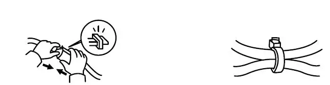
SYSTEM CONTENTS
SYSTEM SPECIFICATIONS
| No. | ITEM | SPECIFICATIONS |
| 1 | Operating Temperature | -40ºC~ +85ºC |
| 2 | Storage Temperature | -40ºC ~ +90ºC |
| 3 | Environmental Protection Level | Radar:IP67 |
| 4 | Input Voltage Range | 12V (9V – 16V) |
| 5 | Current Consumption | 500mA@12V ; 6. 0W |
| 6 | Alarm Level | Level I :LED On (Constant) Level II:LED Flash+Buzzer On |
| 7 | Accuracy of Alarm | Vehicle: >99% |
| 8 Specifications | ISO 17387/IS0 16750 | |
| 9 | Radiation Regulations | FCC / NCC / VSCC |
| 10 | Buzzer | 75dB |
| 11 | Warning Indicator | 5V Drive, A Pillar |
| 4. SYSTEM LAYOUT | ||
SYSTEM LAYOUT
INSTTALLATTIION
TOOLS REQUIRED
SYSTEM BLOCK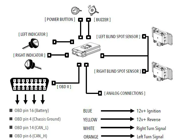
INSTALLATION
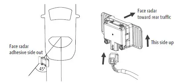
- Measure the rear bumper locating a point suitable for installation which aims the sensor 45 degrees from the centerline of the vehicle. Along that axis, locate a position 19.5 to 28 inches from the ground what is parallel to the ground for the sensor to be installed inside the bumper. Mark this location with painter’s tape on the outside of the bumper cover.

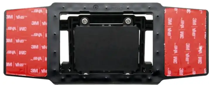
- Remove the bumper cover and clean the inside of the cover where the sensor is to be placed. The area should be cleaned so that the adhesive pad on the sensor assembly may be securely attached. Affix the sensor to the bumper cover taking note of the direction, orientation, and designated location.
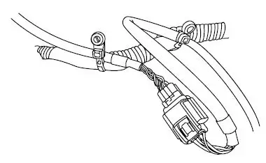
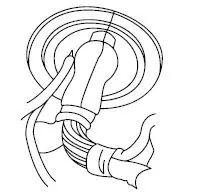
- Connect the left and right radar sensors to the harness. Route the harness assembly from the rear exterior of the vehicle into the cabin utilizing a grommet. Secure the harness away from the heat sources and moving parts. Affix it to the vehicle using cable ties.

- Pass the harness through the grommet ensuring the harness and connector do not become damaged. Route the harness to the desired location where the Control Unit will be installed.

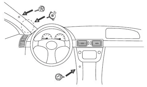
- Instructions for A. indicator, B. buzzer & C. BSD power button.
- Select locations for the right & left indicators to be installed, check for clearance behind the panel. Mark the locations to be drilled with the provided tool. Drill holes. Snap into place.
- Locate a suitable location for the buzzer around the A pillar for maximum effect and ease of installation. Affix the buzzer using the adhesive patch or wire ties.
- Locate a suitable location for the BSD power button which is accessible to the driver, inspect the area behind the panel for clearance. Drill a hole for the button and insert the button into the hole.

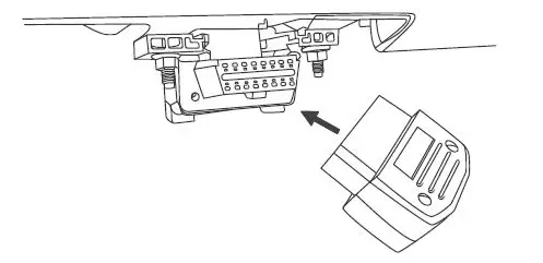
- Locate the OBD-II connector and connect the adapter to the socket. Route the harness to the desired location for the Control Unit to be installed.

- Connect IGN lead to a switched power source (i.e. cigarette lighter, radio accessory power, ignition switch). Connect REVERSE lead to the 12v+ reverse source (i.e. reverse light circuit, integration module output). Connect DIRECTION R and DIRECTION L leads to their corresponding turn signal sources (i.e. tail lamp, side marker, front turn signal). The turn signal leads also accept PWM signal sources in most cases.
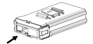
- Connect all the connections then route the harness to the Control Unit and affix the unit in a safe location in the vehicle (i.e. under the dashboard, under the seat, inside the console). Connect the harness connector to the Control Unit.

ERROR DIAGNOSTICS
It is possible that the Blind Spot Detection System will trigger an alert even though there is no vehicle in the blind spot zone. The Blind Spot Detection System can detect objects such as: construction barrels, guard rails, lamp posts, etc. Occasional false alerts are normal.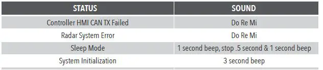
TROUBLESHOOTING
| ISSUE | SYMPTOM | POSSIBLE CAUSE | POSSIBLE SOLUTION |
|
Power On Self-test | The system does not respond after starting the engine | Incorrect connection or control unit failure | Confirm that the IGN, wiring, fuse, and controller are connected. |
| The indicator does not light up | Damaged indicator | Contact your dealer | |
| Disconnected indicator | Verify connection | ||
| The buzzer makes no sound | Damaged buzzer | Contact your dealer | |
| Disconnected buzzer | Verify connection | ||
| The power switch does not work | Damaged power switch | Contact your dealer | |
| Disconnected power switch | Verify connection, press and hold the switch for 2 seconds. | ||
| System Operation | [ Do Re Mi ] alarm | Radar disconnection or no OBD connection | Abnormal power supply, wiring, or radar, please contact your dealer. |
| Did not enter sleep mode after 5 minutes of IGN off | IGN lead connected to constant power | Change the IGN to a switched power source connection location | |
|
Functions |
No Level 1 BSD alert | Vehicle speed is less than 12 mph | Normal operation |
|
Bad connection from OBDII | The vehicle is not compatible. Please contact the dealer. | ||
| Press the RESET button on the control unit after starting the engine. Check the system again after the reboot is completed. | |||
| No Level 2 BSD alert | Turn signal leads not connected | Confirm turn signal leads are connected | |
| No RCTA alert | Reverse lead not connected | Confirm that the reverse lead is connected |
BLIND SPOT DETECTION SYSTEM: For Passenger Vehicles
- 250 Benton Ct, City of Industry, CA
- 714.784.6687
- www.buyblindspot.com.
- [email protected].


