![]()
![]()
![]() Replacement Radio Fits
Replacement Radio Fits
Owner’s Manual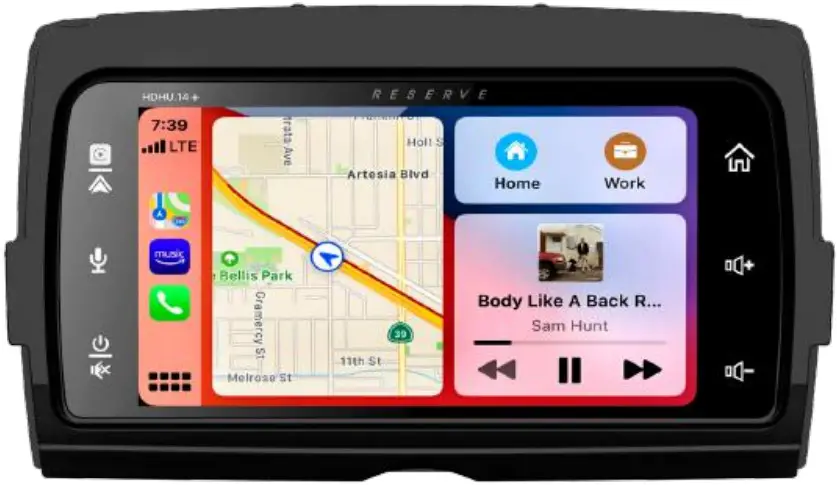
![]()
Safety First
Safety Definitions
Statements in this manual preceded by the following words are of particular significance:![]() WARNING
WARNING
WARNING indicates a potentially hazardous situation that could result in death or severe injury if not avoided.![]() WARNING
WARNING
Set volume levels and other controls on audio and electronic devices before riding. Distractions can lead to loss of control, resulting in death or serious injury.![]() WARNING
WARNING
Do not select a volume level that blocks out traffic noise or interrupts the concentration necessary for the safe operation of the Motorcycle. Distractions or a volume level that blocks our traffic noise could cause loss of control resulting in death or severe injury.
Note
Pay attention while riding, keeping your eyes and clear mind on the road. Some features are locked out to prevent distraction, limited in capability while the Motorcycle is in motion. Even if a part is available, do not allow it to distract you from operating your Motorcycle safely.
For safety, program the system when stopped. Perform system setup and get familiar with the controls and features of the infotainment system before operating the Motorcycle on the road.
This system cannot warn about the safety of an area, bad road conditions, and availability of emergency services.
Use this radio only in locations where it is safe to do.
Before You Ride
Checklist
Configure the system with your personal preferences before riding to use features and minimize distractions while on the road entirely.
- Set brightness, and background.
- Configure presets.
- Adjust audio settings like EQ, volume, fade, balance, etc. before ridding.
- Pair, connect, and set up phone features through Bluetooth.
- Connect USB devices for Apple CarPlay ® or Android Auto ® .
- Select station or media.
CARE AND CLEANING
Use only HDHU.14+ recommended products and methods to keep the radio, speakers, and other audio system components clean and in good condition.
Do not use any abrasives, polishes, or rubbing compounds to clean the screen or other components. Do not use any ammonia-based cleaners on the net. The use of other products or methods may cause damage to components.
Screen:
Do not use any chemical cleaners or chemical-containing wipes or cloths. These can cause damage to the screen surface.
Gently clean the display glass surface with a clean, dry microfiber cloth. Before cleaning, it is suggested to remove any visible dust, dirt, or sand particles with a gentle compressed air stream.
Appearance
Accessories and Installation
Installation
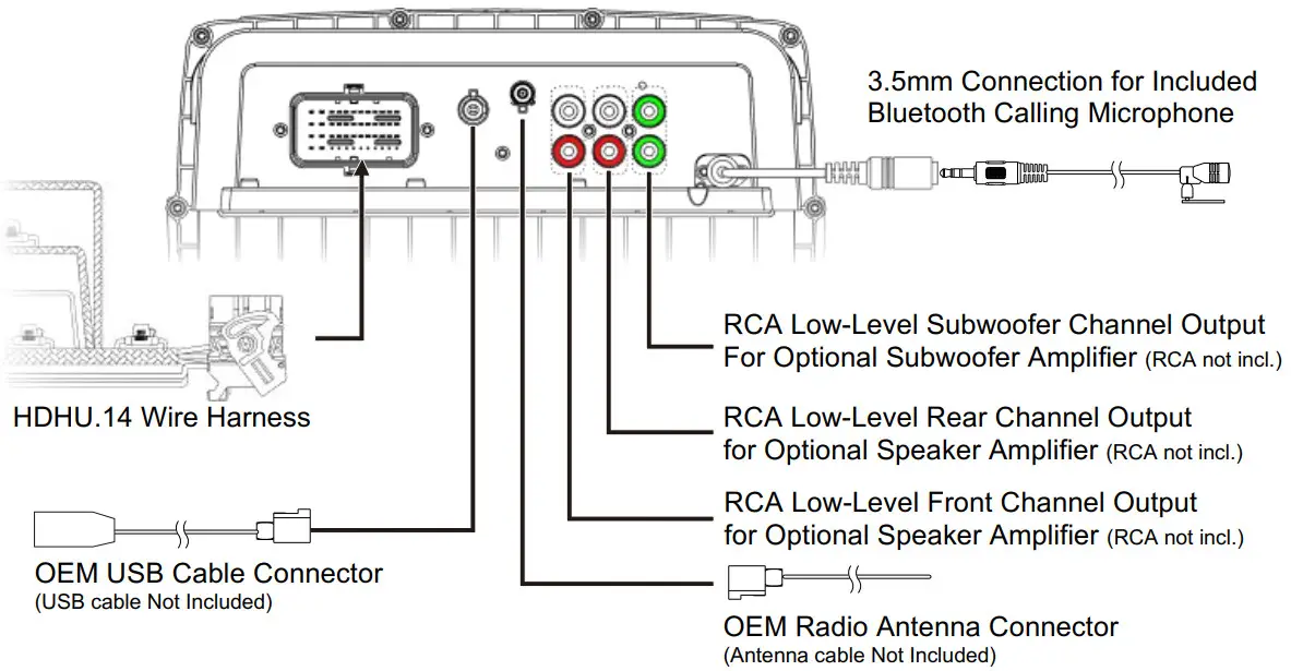
- USB Fakra Connector
Connect the OEM USB cable to the USB connector for playback of Android smartphones, iPhone - AM/FM Radio
Connector Connect the Radio Antenna from HD Motorcycle. - External Microphone Connector
Connect the External Microphone. (Used for Voice Command Function)
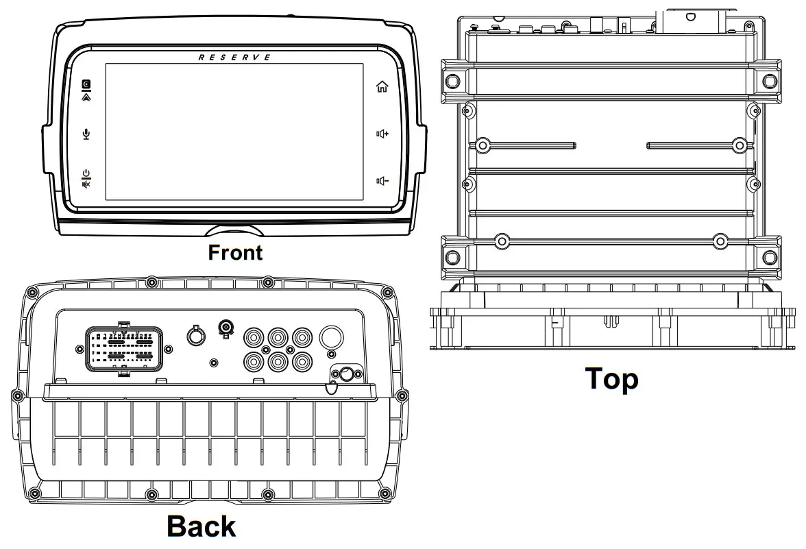
Panel Description
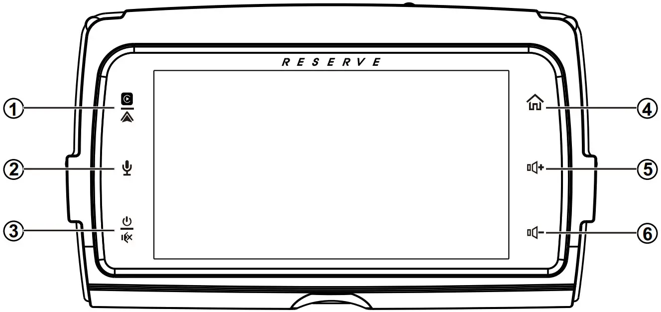
- Apple CarPlay®/ Android Auto®
Press to enter CarPlay® / Android Auto® directly(When the iPhone/Android phone is connected). - SIRI Button Voice Recognition
Press to enter CarPlay® / Android Auto® directly
(When the iPhone/Android phone is connected). - Power / Mute
• When the power is off, press to power on.
• When the unit is working, short pressing for Mute, press again for unmute.
• Pressing and holding to turn the source unit power off.  Home button
• Press to toggle between the home screen and active media.
• Available selections: Radio, Apple CarPlay®/ Android Auto@, BT Music, BT Phone, USB, Settings. (Volume +)
• Press to increase the volume value. ( Volume -)
• Press to decrease the volume value.
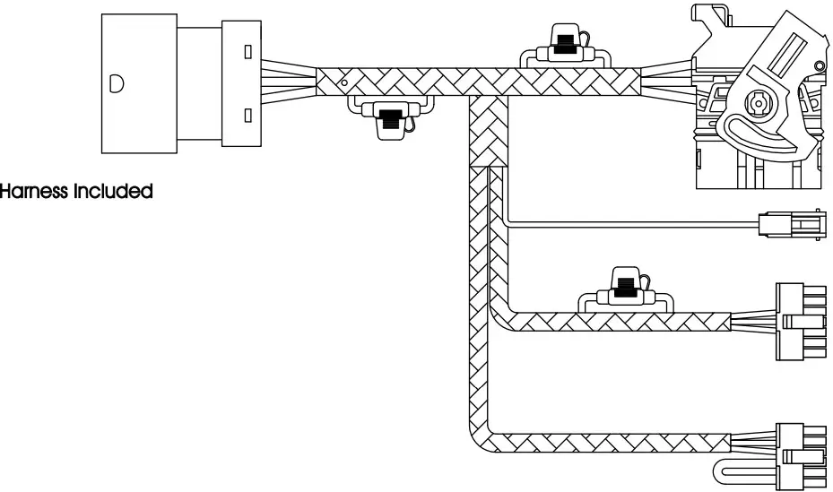
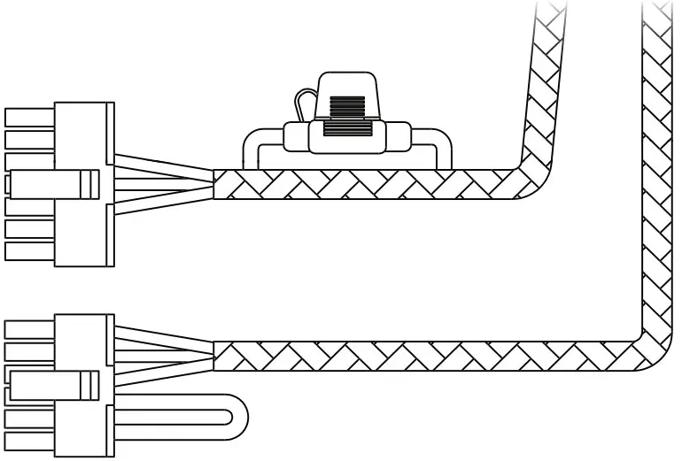
Wiring
Included Harness
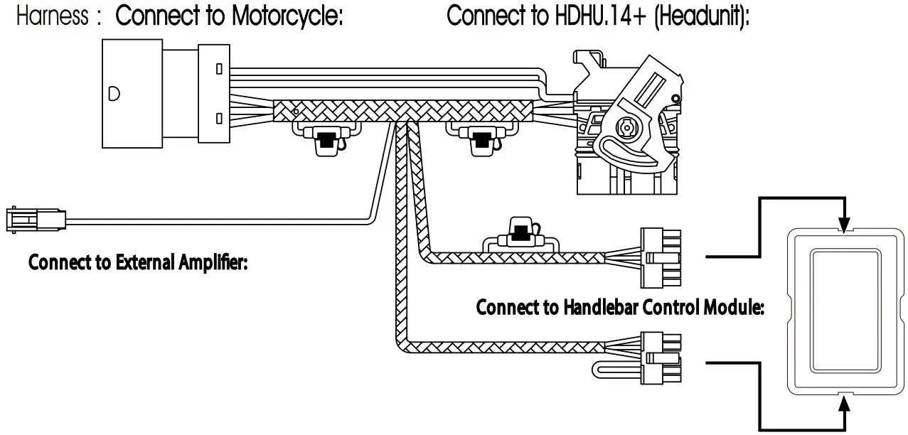 Note: The Handlebar Control Module is Not Included
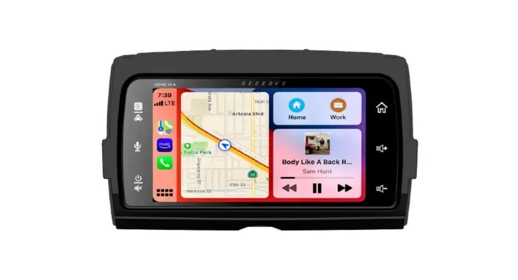
HDHU.14+ is a head unit for Motorcycle with the following functions:
Apple CarPlay ®, Android Auto ®, Radio, USB, BT Music, Phone.
Touch the corresponding Mode icon to enter playing mode. The Mode icon in gray means the corresponding function is not ready, or the proper device has not been connected.
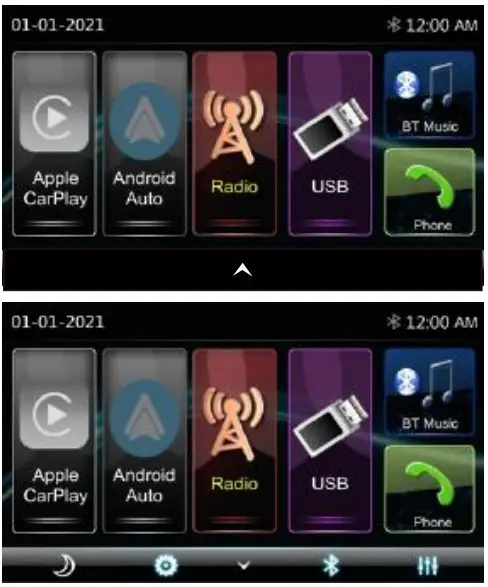
Hidden soft button bar:
A hidden pop-up soft button bar is located at the bottom. Touch the icon ![]() to show the soft button bar. Touch the
to show the soft button bar. Touch the ![]() to hidden.
to hidden.![]() Dimming, to change Daylight or Night (If illumination detection is OFF in Display Setting)
Dimming, to change Daylight or Night (If illumination detection is OFF in Display Setting)![]() Setup to enter the Settings Menu.
Setup to enter the Settings Menu.![]() Bluetooth pairing.
Bluetooth pairing.![]() EQ, to enter the Equalizer setting menu.
EQ, to enter the Equalizer setting menu.
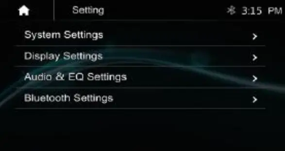
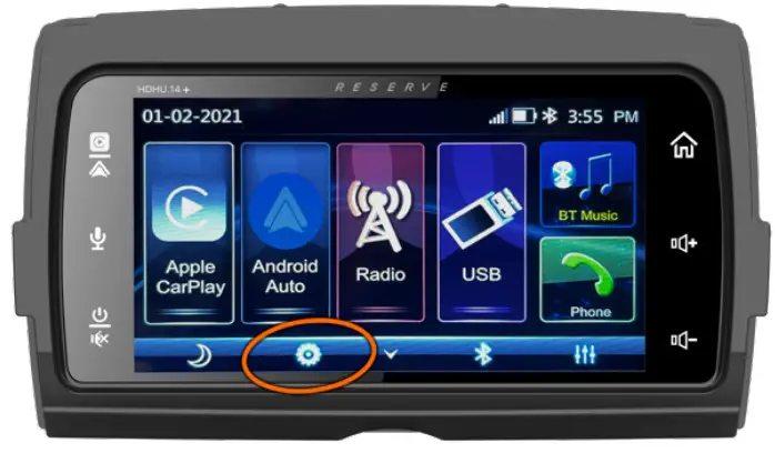
Settings
Touch the ![]() icon to enter the Setup menu.
icon to enter the Setup menu.
The Setup menu is included System Settings, Display Settings, Audio & EQ Settings, and Bluetooth Settings!”
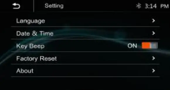
System Settings
The System Settings allow the user to set up the Language, Date & Time, Key Beep, Factory Reset, and About
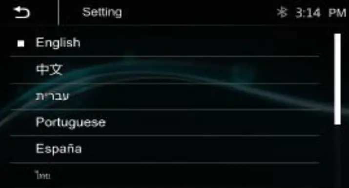
Language
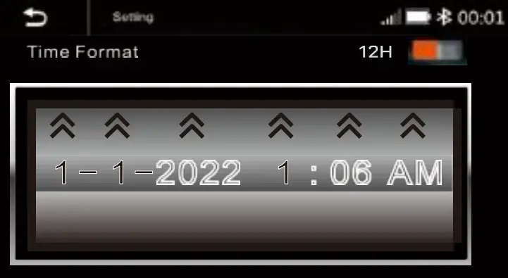
Date & Time:
To setting the Time display format (12H or 24H), setting the date and time
Beep Tone: On / Off
To set the touch button beep tone is On or Off.
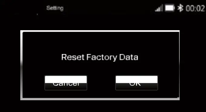
Factory Setting:
To default the default factory settings:
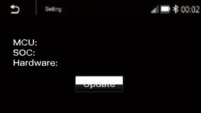
About:
To display the HDHU.14+ hardware and firmware version.
Display setting:
Below is the Display setting menu; users can select Lighting Detect, Daylight Dimming Level, Night Dimming Level, Illumination, and Wallpaper.
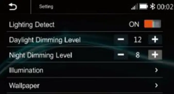
Lighting Detect: On/Off
Daylight Dimming Level: 8 – 15
Night Dimming Level: 0 – 8
Illumination
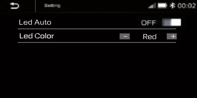
Led Auto: On/Off.
ON: The Led color will change automatically.
OFF: You press the button![]() or
or![]() select desired color.
select desired color.
Color: White / Red / Yellow /Blue / Green /Purple / Light Green
Wallpaper:
Users can select the preset wallpaper or select preferred pictures in the USB driver as the wallpaper.
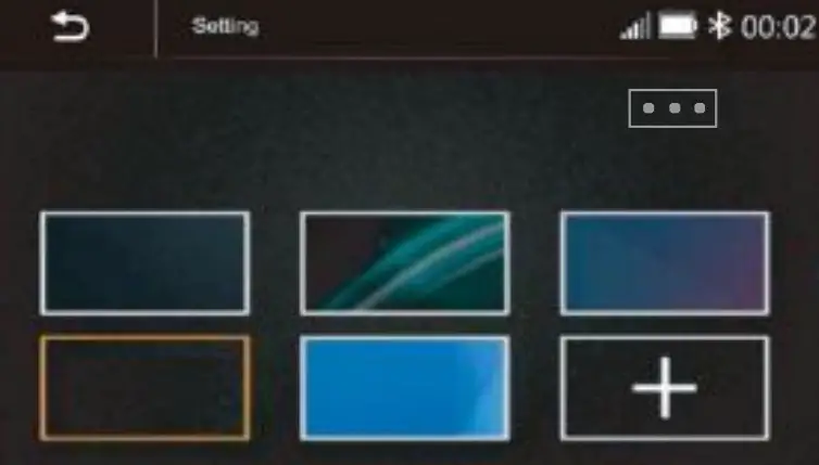
Touch the corresponding picture to select the preferred background.
Touch “+, “the head unit will search the USB photo file for wallpaper.
Select a picture and touch OK to add the wallpaper.![]() Select another picture for replacing the current wallpaper.
Select another picture for replacing the current wallpaper.
Audio & EQ Setting
Below shown is the Audio settings menu.
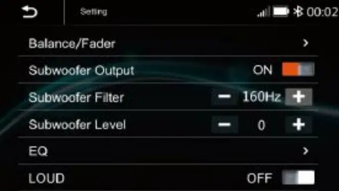
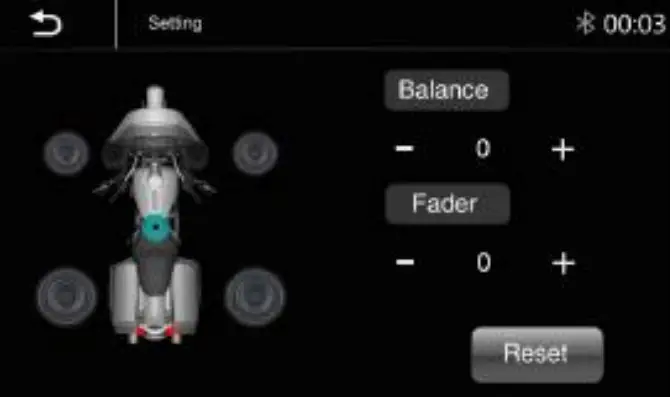
Balance/Fader:
Touch the + or – of Balance/Fade to tune for the driver and passenger preference.
The value of Balance (Left 12 – Right 12) and
Fade (Front 12 – Rear 12)
Touch Reset to set both Balance and Fade to zero
Subwoofer Output: On/Off
Subwoofer Filter: 50Hz, 80Hz,120Hz,160Hz
Subwoofer Level: -10 ~ +10
10- Band Equalizer:
10 – a band of EQ tuning, slide the EQ bar to tune each band frequency level according to user preference.
Touch the Reset button to sell all Bands to zero.
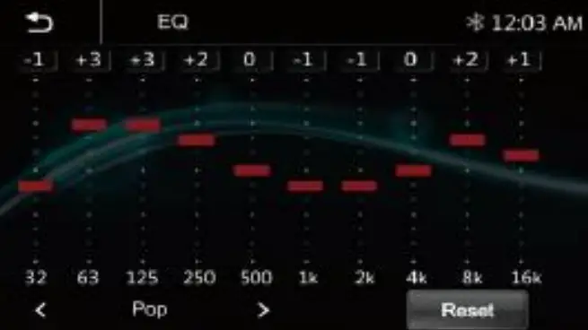
Or user can touch “<” or “>” at the bottom to select the following preset EQ:
Off, Soft Rock, Pop, Electric, Jazz, EQ Custom.
Bluetooth Settings
Touch the Bluetooth Settings from the setting the menu will be shown below:
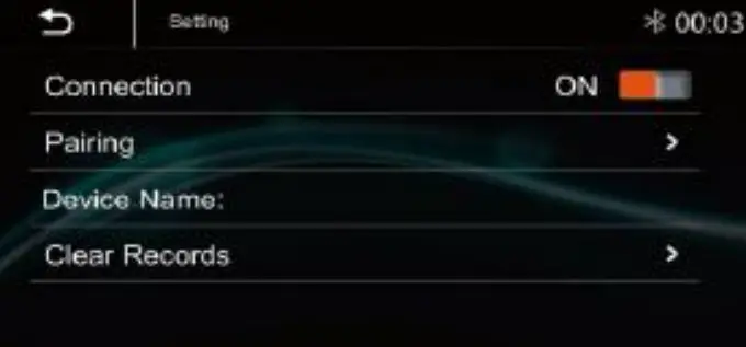
Connection: On/Off (Select Bluetooth connection is On or Off).
Pairing: To start the paring.
Device Name: Shown the connected Phone or device name.
Clear Records: To clear the device list records.
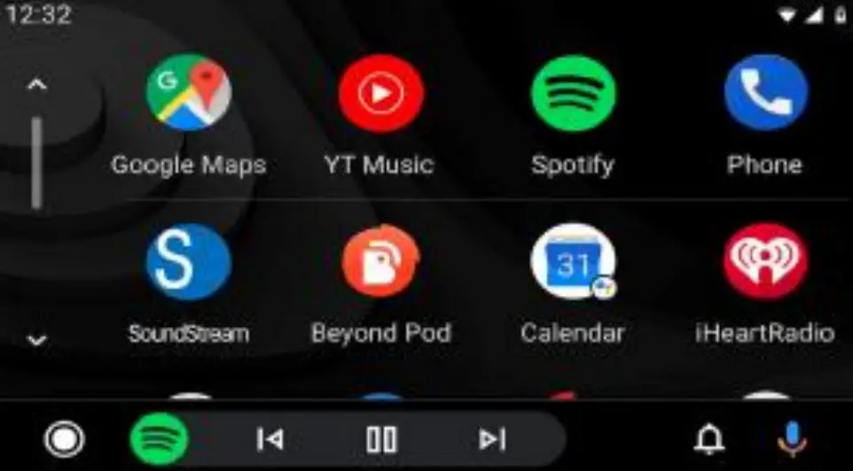
Apple CarPlay ® & Android Auto ®
Apple CarPlay®:
Plug the iPhone (iPhone 5 or later models, and IOS 7.1 or above) through the lightning cable to the USB port of the source unit. The iPhone will be shown the “CarPlay.” The source unit will enter the CarPlay interface, and the APP that supports the CarPlay feature will be displayed on the source unit. Touch the corresponding APP can operate.

Siri:
In CarPlay mode, the user can talk to SIRI to Control the CarPlay ® functions. Press ![]() to start the SIRI function, touch the button for 2 seconds, or the iPhone’s
to start the SIRI function, touch the button for 2 seconds, or the iPhone’s ![]() HOME button. Now you can talk to Siri about playing music; I am going…
HOME button. Now you can talk to Siri about playing music; I am going…
Note: For the SIRI function in the source unit, the microphone must be connected.
In CarPlay ® mode, touch the” Home” button or ![]() Icon to go back to the main menu of the source unit.
Icon to go back to the main menu of the source unit.
Android Auto ®:
Android Auto ® enables you to use functions of your Android device convenient for driving. You can easily access route guidance, make calls, listen to music, etc. For details about Android Auto ®, visit https://www.android.com/auto or https://support.google.com/androidauto
Compatible Android devices
You can use Android Auto with Android devices of Android version 5.0 or later.
Note: Android Auto may not be available on all devices and is unavailable in all countries or regions.
Operation:
- Connect an Android device via a USB terminal. To use the hands-free function, connect the Android device via Bluetooth. When an Android device compatible with Android Auto is connected to a USB terminal, the device is connected via Bluetooth automatically, and the Bluetooth smartphone currently connected is disconnected.
- Unlock your Android device
- To enter Android Auto mode, touch the Android Auto icon on the head unit screen. You can perform the operations of the Apps of the connected Android device.
- In the Android Auto model, touch “Home” on the head unit main menu.

Radio
Touch “Radio” in the main menu to enter the radio interface.
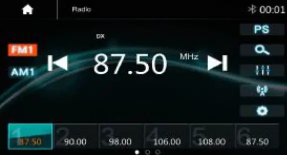
| Touch “FM” can change between FM1>FM2>FM3. | |
| Touch “AM” can change between AM1> and AM2. | |
| Touch for pre-scan search; each scan station will be played for 3sec, and touch again to stop. | |
| Touch to auto-scan searching. | |
| Touch to enter EQ settings. | |
| Touch to switch Local or DX. | |
| Touch to enter Radio settings. | |
| Short touch to seek down, long touch to tune down. | |
| Short touch to seek up, long touch to tune-up. |
Preset channel, six preset buttons store, and recall stations for each band. Touch and slide the preset channel can switch to the next band, FM1/FM2/FM3 or AM1/AM2.
Store a Station
- Tune the radio to the desired station.
- Touch and hold one of the preset stations for more than 3 seconds, then the reset button will be highlighted on the screen, and the preset station will be stored.
Radio setting:
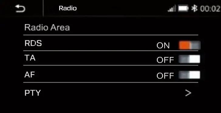
Radio Area: Select the region, American/Europe /Eastern Europe /Japan /Southeast Asia /Latin American/ Asia / Australia.
RDS: Switch ON or OFF.
TA: Switch ON or OFF.
AF: Switch ON or OFF.
PTY: Switch ON or OFF.
Note: AF is only for the European region.
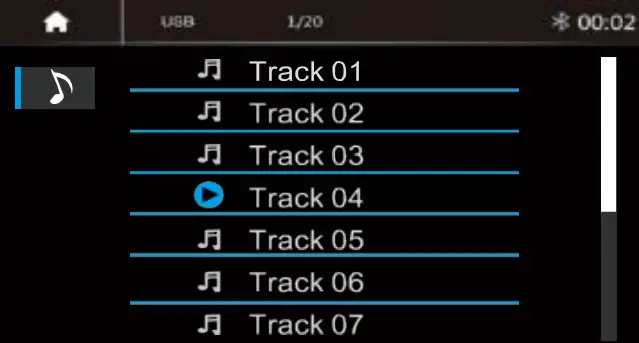
USB
Plug the USB; the USB icon will be colorful. Touch the USB icon to enter the USB playback mode. The source unit will playback the audio in the USB device.

| Press to go to the following folder. | |
| Press to search Audio files. Press | |
| to go to the previous folder. |
USB
| Short press to skip a previous track. Long press to fast reverse. | |
| Play or Pause button. | |
| Short press to skip the next track. Long press to fast forward. | |
| Press to select Repeat All> Repeat 1> Repeat Folder. | |
| Press to switch Random is On or Off. | |
| Press to select an Audio setting or set the preferred EQ of each band in custom mode. |
File List Browsing
Touch ![]() to browse the folder and file list of the USB device.
to browse the folder and file list of the USB device.
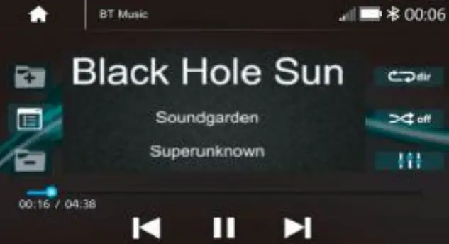
Bluetooth Music:
Touch the BT Music icon to enter Bluetooth Music playing mode. If the Bluetooth is connected, the music will be playing as below shown:
Bluetooth
| Press to search Audio files. | |
| Short press to skip a previous track. Long press to fast reverse. | |
| Play or Pause button. | |
| Short press to skip the next track. Long press to fast forward. Press to select | |
| Repeat All> Repeat 1> Repeat Folder. | |
| Press to switch Random is On or Off. | |
| Press to select an Audio setting or set the preferred EQ of each band in custom mode. |
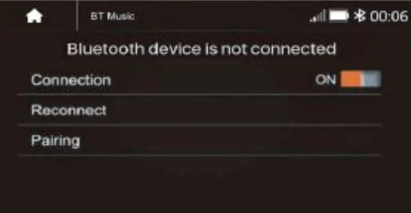
Bluetooth Connect:
If the Bluetooth is not connected, press Reconnect the paired Phone or paring to pair the new device.
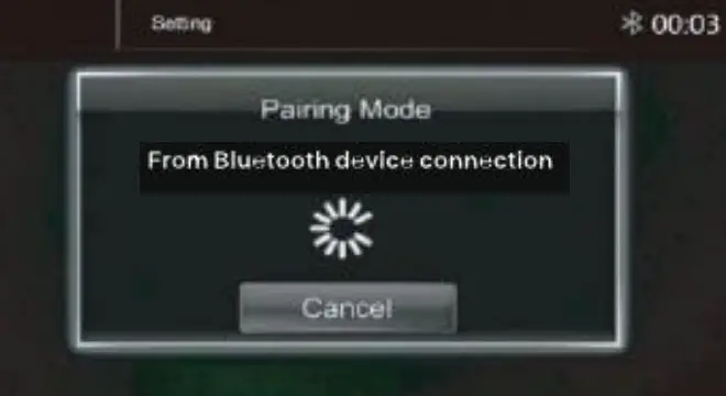
Bluetooth Pairing:
The pairing screen will be shown as below:
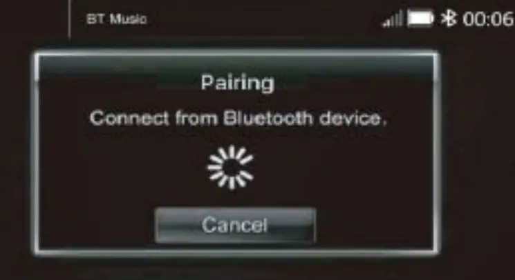
Turn on the Bluetooth of the Mobile phone/ Bluetooth device; you can see the “SOUNDSTREAM HD.”
Select the “SOUNDSTREAM HD” for paring and connection.
Bluetooth Phone
Bluetooth Phone:
After the mobile phone is connected to the source unit via Bluetooth (HFP), the user can go through the source unit
Make a phone call. Touch the Phone icon in Main Menu to go to BT Phone mode. Please note it needs to connect the microphone for phone calls.
| Keypad. Tap it to enter call mode. | |
| History. Tap it to show the call record, missed, received, and dialed calls. | |
| Contact. Tap it to show the phonebook of the connected device. | |
| BT Setup. Tap it to set Auto answer and Microphone gain. | |
| Make a call or accept the incoming call. | |
| Backspace, tap it to clear the incorrect dial digit. |
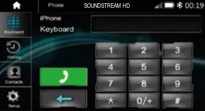
Make a Call:
- Touch the
 icon to enter the dial screen.
 - Touch 0-9, *, #, #, use the keypad, and enter the desired number to dial. If you input an incorrect number, touch the
 icon on the keypad to delete the wrong number.
 - Once the correct number appears on the screen, touch the
 icon to go to the dialing interface.
 - To end the call, touch the icon
 on the screen.
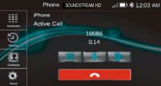
Receive an incoming call:
If the phone is connected to the source unit via Bluetooth, when an incoming call, the below screen will be shown:
Press ![]() to answer the incoming call.
to answer the incoming call.
Press ![]() to reject the incoming call.
to reject the incoming call.
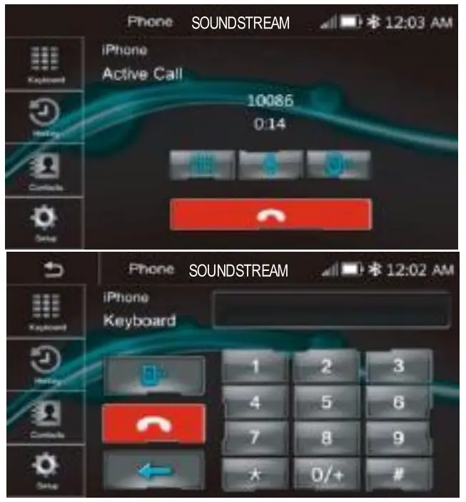
| The interchange between phone and source unit. | |
| Toggle On / Off the Microphone function. | |
| Display the Keypad. |
Call List:
Touch the![]() icon to display the call combined list.
icon to display the call combined list.
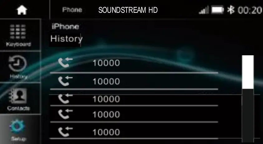
Slide the bar on the right up and down to display call logs.
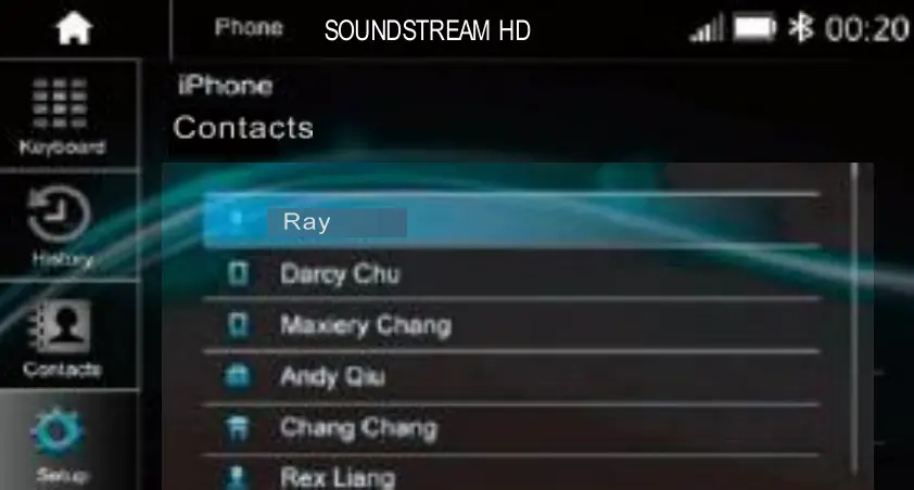
Contacts:
Touch the ![]() icon to access the phone book of the connected mobile phone.
icon to access the phone book of the connected mobile phone.
To make a call from the phonebook, simply touch the contact’s name.
BT Setup:
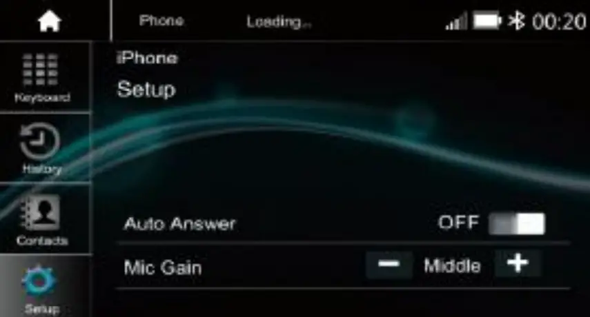
Auto Answer: On/Off, incoming call auto answer.
MIC Gain: Low /Middle /High
HDHU.14+ Specifications
| GENERAL | |
| Power Requirement: | DC 10 – 16Volts, |
| Power Requirement: | Negative ground |
| Current Drain: | 15A (Max.) |
| Maximum Power Output: | 50Watts x 4 |
| RMS Power Output: | 25Watts x 4 |
| Speaker Impedance: | 2- or 4-Ohm Load |
| Frequency Response | 20Hz ~20KHz |
| Operating temperature: | -20~60 ℃ |
| Dimensions: | 230mm(W) x 210mm(D)x 140mm(H) |
| TFT Display | |
| TFT Screen size: | 7 – Inch TFT/LCD |
| Resolution | 1024 x 600 pixels |
| FM RADIO SECTION | |
| Frequency Range | 87.5 – 107.9 MHz (America) 87.5 – 108 MHz (Europe) |
| Usable Sensitivity (S/N=30dB) | ≤15dB |
| S/N Ratio: | ≥55dB |
| Stereo Separation | ≥30dB |
| AM RADIO SECTION | |
| Frequency Range | (America) 522 – 1620 kHz (Europe) 530 – 1710 kHz |
| Usable Sensitivity (S/N=20dB) | ≤40dB |
| S/N Ratio: | ≥45dB |
| Line-out / Subwoofer Output | |
| Maximum Output Leve (10K ohms load): | ≥4V RMS |
| Subwoofer Time Align | 0~18ms |
Trouble Shooting
| Problem | Cause | Correct action |
| No Power, Dead. | Check Fuse | Replace Fuse |
| Incorrect Wiring | Consult your Local Specialist. www.MotorcycleAudio.com/Specialist-Locator | |
| No sound output when operating the unit with amplifiers or power antenna attached. | Power antenna lead is shorted to ground excessive current is required or remote on the amplifiers or power antenna | 1. Turn off the unit. 2. Remove all wires attached to the power antenna lead. Check each wire for a possible short to the ground using an ohm meter. 3. Turn on the unit. 4. Reconnect each amplifier remote wire to the power antenna lead one by one. If the amplifiers turn off before all wires are attached, use an external replay to provide remote-on voltage (excessive current required). |
| Poor performance of radio station | Weak signal | Move the Motorcycle to another place, then try again |
| No Sound or Audio | Volume is at minimum The wiring is not properly connected. | Adjust volume to the desired level. Check to wire connection |
FCC Notes
WARNING! NOTE: This equipment has been tested and found to comply with the limits for a Class B digital device, pursuant to Part 15 of the FCC Rules. These limits are designed to protect reasonably against harmful interference in a residential installation. Changes or modifications to this unit not expressly approved by the party responsible for compliance could void the user’s authority to operate the equipment.
This equipment generates, uses, and can radiate radio frequency energy and, if not installed and used in accordance with the instructions, may cause harmful interference to radio communications.
Suppose this equipment does cause harmful interference to radio or television reception, which can be determined by turning the equipment off and on. However, there is no guarantee that interference will not occur in a particular installation. In that case, the user is encouraged to try to correct the interference by one or more of the following measures:
- Reorient or relocate the receiving antenna.
- Increase the separation between the equipment and receiver.
- Connect the equipment into an outlet on a circuit different from that the receiver is connected to.
www.MotorcycleAudio.com
Follow Us on Social Media![]()
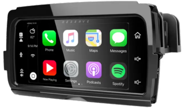
RESERVE by SOUNDSTREAM®
UPGRADE HEAD UNIT FOR 2014+ HARLEY DAVIDSON® MOTORCYCLES
INSTALLATION GUIDE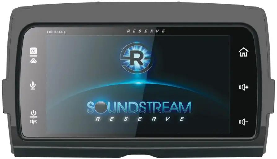
![]()
To print the complete owner manual, visit us online at motorcycleaudio.com/hdhu.14
– or –
Scan this QR code with your phone’s camera to download the complete owner’s manual to your phone.
 https://motorcycleaudio.com/manuals/HDHU-14_Owners_Manual.pdf
REMOVAL OF ORIGINAL HEAD UNIT
STREET GLIDE
To prevent accidental vehicle start-up, which could cause death or serious injury, remove the main fuse/battery cables before proceeding.
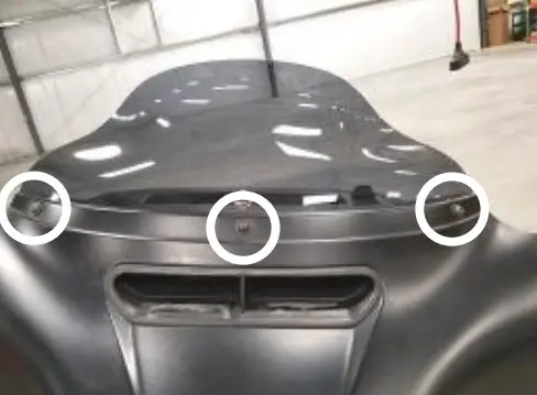
- Remove three outer fairing bolts using a T27 Torx screwdriver. The three outer fairing bolts are located below the windshield. Remove the windshield, store it and the screws removed in a safe place for re-installation later.

TIP: Reinstalling the center screw after removing the windshield will prevent the outer fairing from falling during the next step. A few turns by hand will be sufficient. - Remove four inner fairing bolts using a T27 Torx screwdriver. The four inner fairing bolts are located adjacent to each turn indicator mounting bracket and below/adjacent to each speaker. Store these screws in a safe place for re-installation later.

- While straddling the front wheel fender, grasp the outer fairing, remove the center outer fairing bolt from the previous step, then gently pull the fairing apart from the bike. With the fairing slightly pulled away from the bike, disconnect the wire harness for the headlamp and any other accessories. Lay the fairing on a protected flat surface to prevent damage.
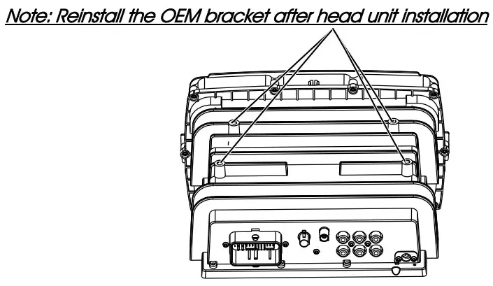
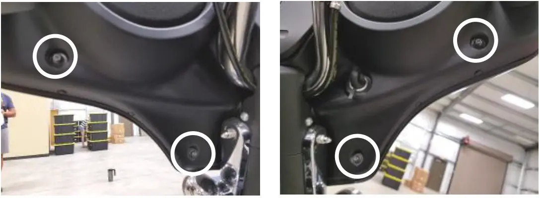
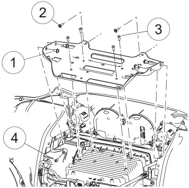
- Remove upper support bracket. Removal of The upper support bracket requires removing 11 screws:
4.1) remove two screws attaching the bracket to each speaker enclosure (1)
4.2) remove two screws attaching the bracket to the inner fairing adjacent to the gauge cluster (2)
4.3) remove four screws attaching the bracket to the head unit chassis (3)
4.4) Remove one screw attaching the bracket to the media compartment (6)
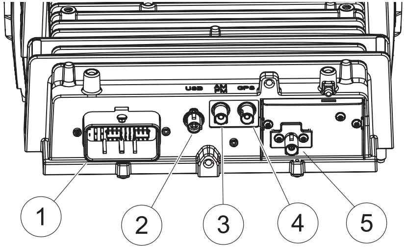
- Disconnect electrical connections to the head unit.
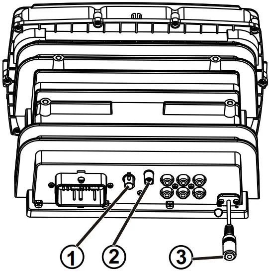
5.1) Remove the main wire harness connector (1). To remove the main wire harness, depress the latch lock with a small flathead screwdriver and swivel the latch aside. Pull the wire harness connector to remove it from the socket.
5.2) Remove the USB cable connector (2). To remove the USB cable connector, depress the locking tab with a small flathead screwdriver. While depressing the locking tab, pull the USB cable to release it from the socket.
5.3) Remove the radio antenna cable connector (3). To remove the radio antenna cable connector, depress the locking tab with a small flathead screwdriver. While depressing the locking tab, pull the antenna cable to release it from the socket.
5.4) Remove the GPS antenna cable connector (4). To remove the GPS antenna cable connector, depress the locking tab with a small flathead screwdriver. While depressing the locking tab, pull the GPS antenna cable to release it from the socket.
5.5) Remove SiriusXM antenna cable connector, if equipped (5). To remove the Sirius XM antenna cable connector, depress the locking tab with a small flathead screwdriver. While depressing the locking tab, pull the Sirius XM antenna cable to release it from the socket.
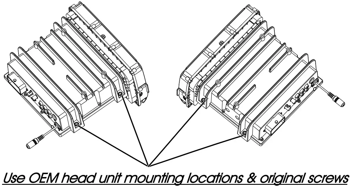
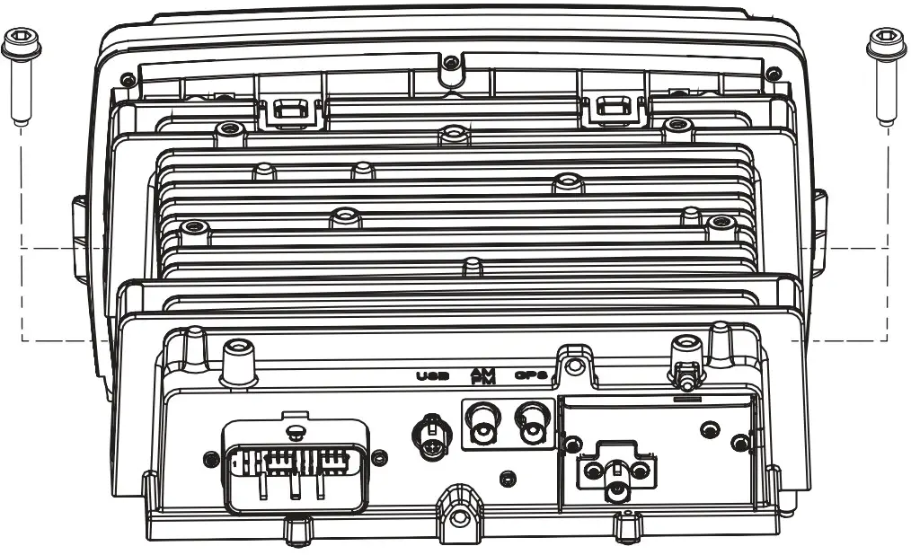
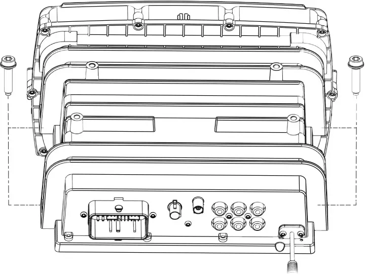
- Remove four head unit mounting screws using a 3/16” hex driver. Two screws are located at each side of the head unit chassis. Store these screws in a safe place for re-installation later. Pull the head unit assembly up and forward to remove.

REMOVAL OF ORIGINAL HEAD UNIT
ROAD GLIDE
To prevent accidental vehicle start-up, which could cause death or serious injury, remove the main fuse/battery cables before proceeding.
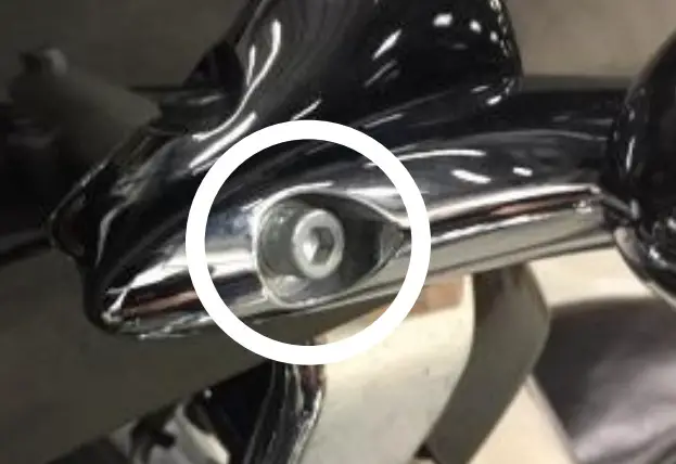
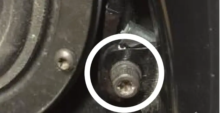
- Detach each turn signal/indicator light by removing the adjacent Allen socket screw, using a 3/16” Allen head driver. Store these screws in a safe place for re-installation later.

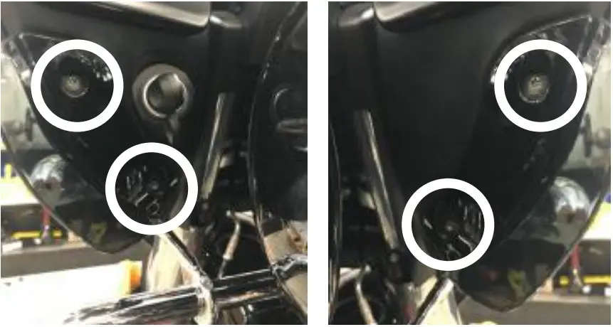
- Remove four inner fairing bolts using a T25 Torx driver. Two inner fairing bolts are located below each glove box, adjacent to each wind deflector. Store these screws in a safe place for installation later.

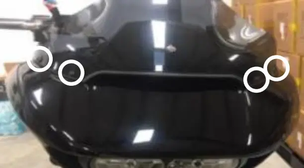
- Remove four windshield bolts using a 1/8” fallen driver or Phillips screwdriver and remove the windshield. Also, remove the factory vent by pulling it straight up on the vent. The vent comes snapped in place. Store the screws in a safe place for installation later.

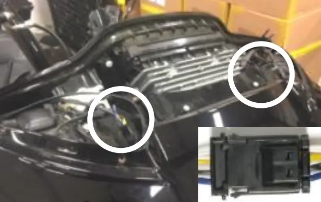
- After removing the vent, locate and unplug the 3-pin wire harness for the left and right side turn signal indicator. These harnesses’ are adjacent to each side of the head unit.

- Remove an additional inner fairing bolt with a T27 Torx or 5/32” Allen driver, one behind each speaker grill. Remove the speaker grill by wedging a plastic/nylon pry tool between the inner fairing and grill edge, popping it outward. Once these bolts are removed, the outer fairing will be detached from the inner fairing. Store these screws in a safe place for installation later.

- While straddling the front wheel fender, grasp the outer fairing. Gently pull the fairing apart from the bike. With the fairing slightly pulled away from the bike, disconnect the wire harness for the headlamp or any other accessories. Lay the fairing on a protected flat surface to prevent damage.

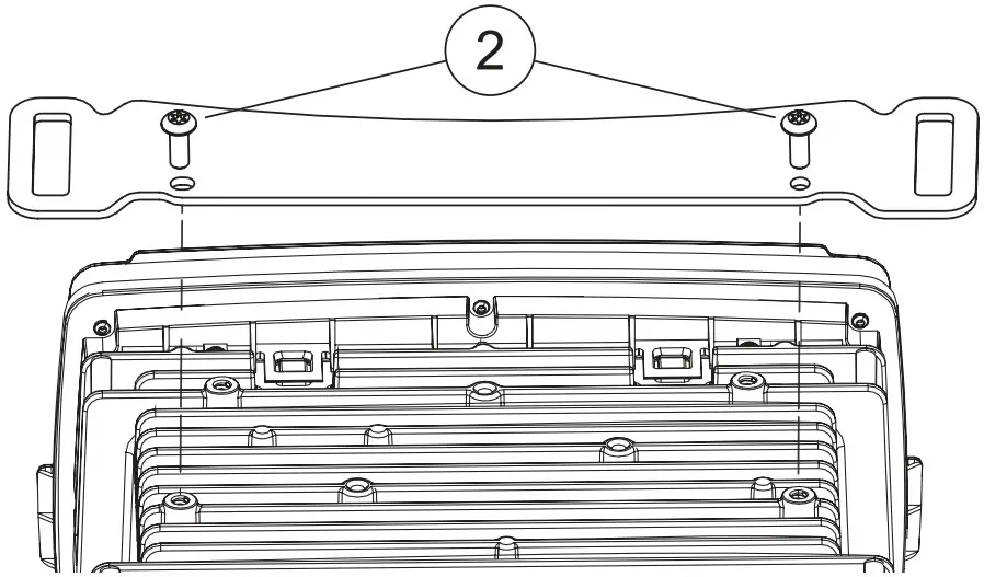
- Remove two upper support bracket screws using a 3/16” Allen driver. Store the bracket and screws in a safe place for re-installation later.
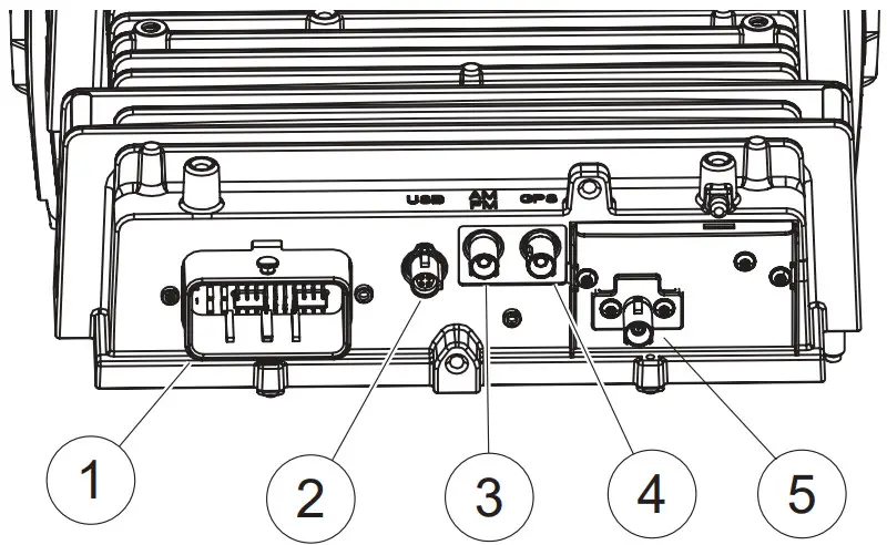
- Disconnect electrical connections to the head unit.
8.1) Remove the main wire harness connector (1). To remove the main wire harness, depress the latch lock with a small flathead screwdriver and swivel the latch aside. Pull the wire harness connector to remove it from the socket.
8.2) Remove the USB cable connector (2). To remove the USB cable connector, depress the locking tab with a small flathead screwdriver. While depressing the locking tab, pull the USB cable to release it from the socket.
8.3) Remove the radio antenna cable connector (3). To remove the radio antenna cable connector, depress the locking tab with a small flathead screwdriver. While depressing the locking tab, pull the antenna cable to release it from the socket.
8.4) Remove the GPS antenna cable connector (4). To remove the GPS antenna cable connector, depress the locking tab with a small flathead screwdriver. While depressing the locking tab, pull the GPS antenna cable to release it from the socket.
8.5) Remove SiriusXM antenna cable connector, if equipped (5). To remove the Sirius XM antenna cable connector, depress the locking tab with a small flathead screwdriver. While depressing the locking tab, pull the Sirius XM antenna cable to release it from the socket.
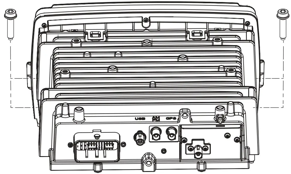
- Remove four-head unit mounting screws using a 3/16” hex driver. Two screws are located at each side of the head unit chassis. Store these screws in a safe place for re-installation later. Pull the head unit assembly up and forward to remove.

INSTALLATION OF HDHU.14 HEAD UNIT
To prevent accidental vehicle start-up, which could cause death or serious injury, remove the main fuse/battery cables before proceeding.
- Install HDHU.14 into the location of the OEM head unit. Secure the chassis to the OEM mounting location with the four bolts removed during the last step of the REMOVAL OF the ORIGINAL HEAD UNIT section using a 3/16” Allen driver.

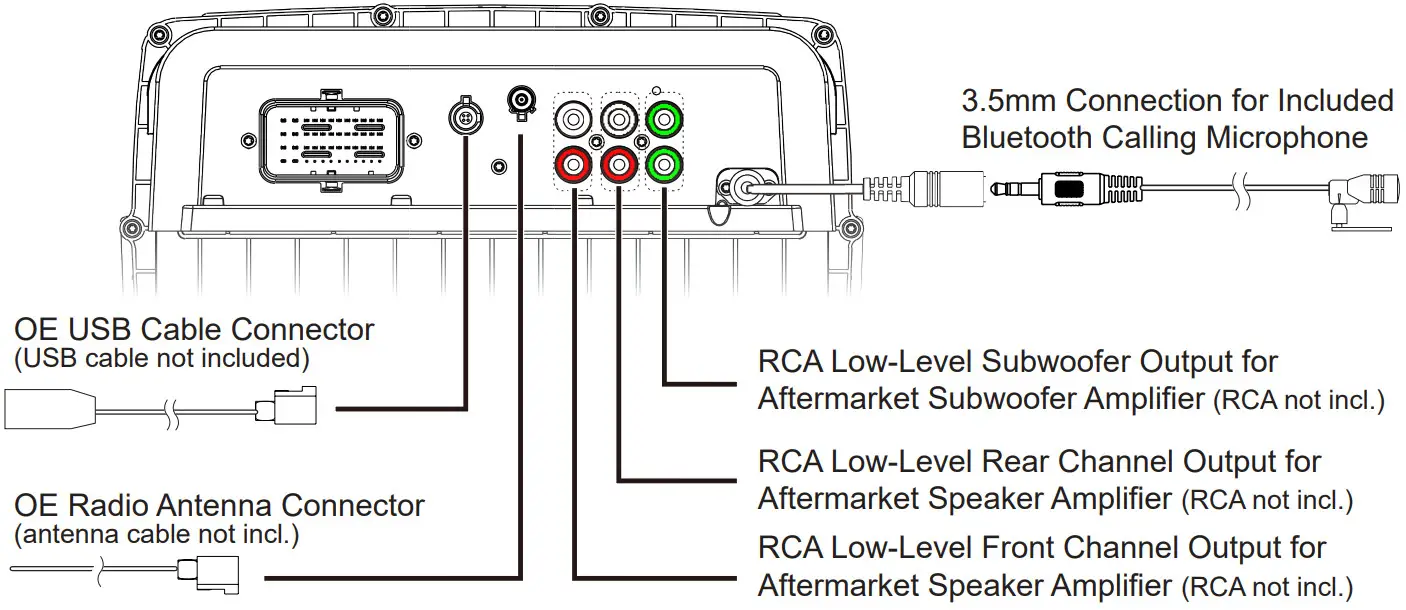
- Connect the OEM USB and radio antenna cables disconnected during removal of the OEM head unit to the matching sockets on the back of HDHU.14. If either is difficult to connect, verify the orientation of the connector(s) is correct. If any aftermarket audio amplifiers will be used in the audio system, take a moment to connect the RCA cables to the corresponding audio outputs. Although not required, if the Bluetooth calling microphone will be used, secure it to the desired installation location, then route its cable to the corresponding input on the back of HDHU.14.

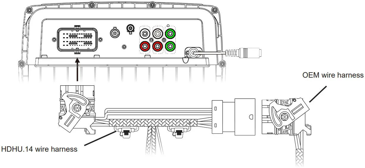
- Insert and lock the male OEM head unit wire harness connector to the female socket of the included wire harness for HDHU.14. Then, insert and lock the male connector of the HDHU.14 wire harness into the corresponding female socket on the back of HDHU.14.

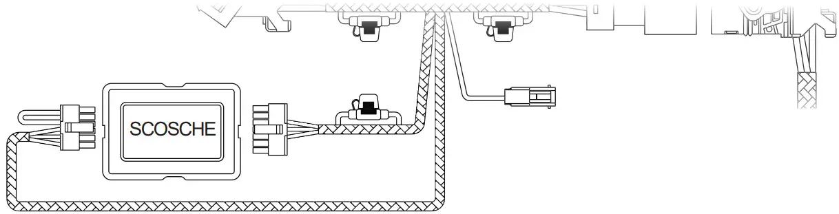
- If an alternative handlebar integration module other than Scosche is available, skip this step and proceed to step 5. If included, connect the Scosche handlebar integration module to the corresponding 12-pin and 14-pin connectors on the wire harness of HDHU.14.

- If an alternative handlebar integration module is available, cut the wires leading to the 12-pin and 14-pin connectors and discard them. Follow the color-coded call-out below to connect the wires of HDHU.14 wire harness to the corresponding inputs and outputs of the alternate handlebar control module.
 14-Pin Connector
Red……………………..ACC turn-on
Orange………………..Illumination
Violet/White………….CAN Green/White…………CAN+
Black…………………..Ground
Yellow………………….12V
12-Pin Connector
Black/White…………..Key/SWC Ground
Green/White………….Key/SWC 1
Grey/White……………Key/SWC 2 - Double check all connections are complete and secure. Reassemble the fairing support bracket using the original screws to the corresponding screw holes on top of HDHU.14. Then, reassemble the fairing by reversing the model-specific instructions covered in REMOVAL OF ORIGINAL HEAD UNIT.

 14-Pin Connector
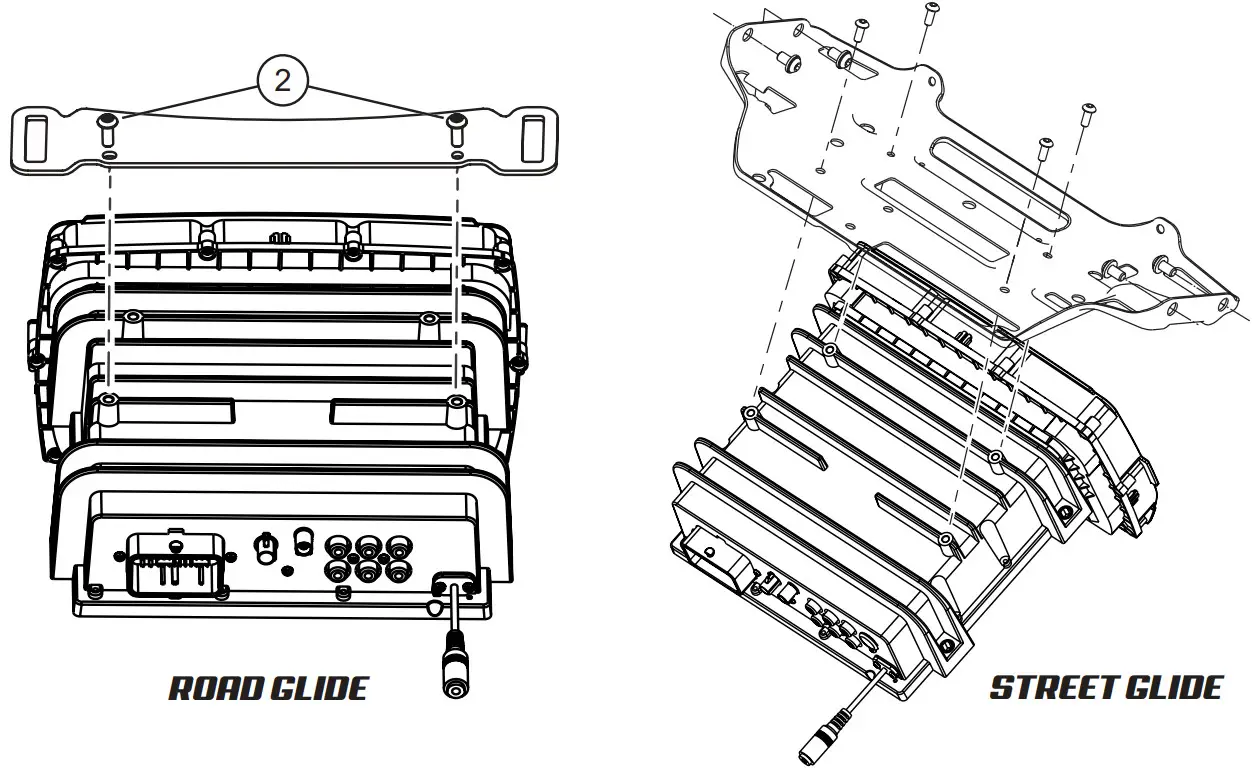
LIMITED 90-DAY CONSUMER WARRANTY
LIMITED ONE-YEAR CONSUMER WARRANTY WITH PURCHASE AND INSTALLATION BY A SOUNDSTREAM TECHNOLOGIES AUTHORIZED DEALER
Soundstream Technologies promises to the original purchaser to repair or replace this product with a new or refurbished unit (at Soundstream Technologies’ sole and absolute discretion) should it prove to be defective in workmanship or material under regular use, for a period of *ONE year from the date of purchase from the Soundstream Technologies authorized dealer, PROVIDED the product was purchased and installed by a Soundstream Technologies authorized dealer. During this *two-year period, there will be no charge for product repair or replacement, PROVIDED the unit is returned to Soundstream Technologies, return shipping pre-paid, along with the required proof of installation, the bill of sale or other dated proof of purchase, and the consumer’s contact information.
If the unit is installed by anyone other than a Soundstream Technologies authorized dealer, the warranty period will be 90-days from the date of purchase. This warranty is non-transferable and does not apply to any unit modified or used in a manner contrary to its intended purpose. It does not cover damage to the unit caused by installation or removal of the unit. During these 90 days, there will be no charge for the repair or replacement PROVIDED the unit is returned to Soundstream Technologies, return shipping prepaid, along with the bill of sale or other dated proof of purchase and the consumer’s contact information.
This warranty is void if the product has been damaged by an accident or unreasonable use, neglect, improper service, or other causes not arising from defects in materials or construction. This warranty does not cover the elimination of externally generated static or noise, the correction of antenna problems or weak reception, damage to speakers, accessories, electrical systems, cosmetic damage or damage due to negligence, misuse, failure to follow operating instructions, accidental spills or customer applied cleaners, wear due to environmental causes such as floods, airborne fallout, chemicals, salt, hail, lightning or extreme temperatures, damage due to accidents, road hazards, fire, theft, loss or vandalism, damage due to improper connection to equipment of another manufacturer, modification of existing equipment, or Product which has been opened or tampered for any reason. Units that are damaged by abuse resulting in thermally damaged voice coils are not covered by this warranty but may be replaced at the absolute and sole discretion of Soundstream Technologies. The unit must be returned to Soundstream Technologies, postage pre-paid, with a bill of sale or other dated proof of purchase bearing the following information: consumer’s name, telephone number, address, authorized dealer’s name, address, and product description. Please contact the Soundstream Technologies warranty office at 800.832.4647 or [email protected] to obtain a Return Authorization number before shipping the product.
Note: This warranty does not cover labor costs for the removal and re-installation of the unit. FOR THE TWO-YEAR WARRANTY TO BE VALID, YOUR UNIT MUST BE SHIPPED WITH PROOF OF INSTALLATION BY A SOUNDSTREAM TECHNOLOGIES AUTHORIZED DEALER. ALL UNITS RECEIVED BY SOUNDSTREAM TECHNOLOGIES FOR WARRANTY REPAIR WITHOUT PROOF OF SOUNDSTREAM TECHNOLOGIES AUTHORIZED DEALER INSTALLATION AND PURCHASE WILL BE COVERED BY THE LIMITED 1-YEAR WARRANTY.
BY PURCHASING THIS PRODUCT, ALL WARRANTIES INCLUDING BUT NOT LIMITED TO EXPRESS WARRANTY, IMPLIED WARRANTY, WARRANTY OF MERCHANTABILITY, FITNESS FOR PARTICULAR PURPOSE, AND WARRANTY OF NON-INFRINGEMENT OF INTELLECTUAL PROPERTY ARE EXPRESSLY EXCLUDED TO THE MAXIMUM EXTENT ALLOWED BY LAW, AND SOUNDSTREAM TECHNOLOGIES NEITHER ASSUMES NOR AUTHORIZES ANY PERSON TO ASSUME FOR IT ANY LIABILITY IN CONNECTION WITH THE SALE OF THE PRODUCT. SOUNDSTREAM TECHNOLOGIES HAS ABSOLUTELY NO LIABILITY FOR ANY AND ALL ACTS OF THIRD PARTIES, INCLUDING ITS AUTHORIZED DEALERS OR INSTALLERS. BY PURCHASING THIS PRODUCT, THE CONSUMER AGREES AND CONSENTS THAT ALL DISPUTES BETWEEN THE CONSUMER AND SOUNDSTREAM TECHNOLOGIES SHALL BE RESOLVED IN ACCORDANCE WITH CALIFORNIA LAWS IN LOS ANGELES COUNTY, CALIFORNIA. Some states do not allow limitations on how long an implied warranty lasts. In such states, the limitation or exclusions of this Limited Warranty may not apply. Some states do not allow the exclusion or limitation of incidental or consequential damages. In such states, the exclusion or limitation of this Limited Warranty may not apply to you. This Limited Warranty gives you specific legal rights, and you may have other rights which vary from state to state.
HDHU.14 Firmware Update
January 31st, 2022
- Download the HDHU.14 Firmware Update and Save to Computer.
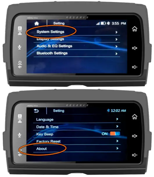
After downloading, make sure the compressed files are unzipped and are copied onto a blank USB Flash Drive (64GB Max) on the Root Directory File of the USB Flash Drive - Insert a USB stick and select the “Settings Icon” from the Home Screen

- Select the “System Settings” tab at the top, then next screen select the “About” button

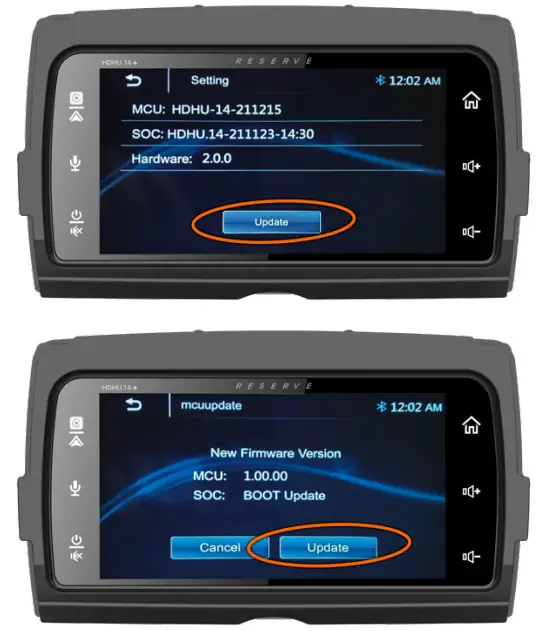
- Select “Update” and on the next screen select “Update” Again

- (( Wait for both Updates to complete ))
Headunit will restart itself once both updates are complete. New Firmware Info:
MCU – HDHU-14-220126
SOC – HDHU.14-220124-12:00
Firmware Improvements:
- Adds 10-Second Amplifier Turn-on Option
- Defaults Key-Beep Alert to “Off”
- Balances the Source Levels (USB, BT)
- Increases Overall Level Before Clipping
- Reduces Intermittent Data Feedback
Need Help? Contact Tech-Support
[email protected]
or 800.832.4647 Monday-Friday
8:30 AM – 4:30 PM Pacific Standard
If Tech Support is busy, please leave a message and you will get a return call within 48 hours of being received.
For Faster Service Email Us


