Cactus M.2 SSD -270PM6 Series Commercial Grade
Product Information
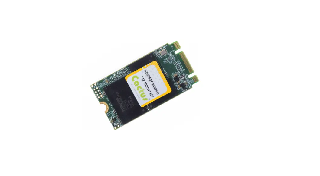
Commercial Grade -270PM6 Series M.2 SSD
The Commercial Grade -270PM6 Series M.2 SSD is a high-performance solid-state drive manufactured by Cactus Technologies Limited. This SSD comes with various features and specifications that make it suitable for commercial use.
Features
- Host and Technology Independence
- Defect and Error Management
- Power Supply Requirements
- Solid state design with no moving parts conformal coated
- Equipped with heat spreader (standard temp. version) or heat sink (extended temp. version) for thermal management
- Capacities of 128/256/512GB
- Available in M.2 2242 form factor
- Native NVMe interface
- Compliant with PCI Express base specifications, ver.3.1
- Compliant with NVMExpress specifications, ver.1.3
- PCI Express Gen3 x4 configuration
- Supports ASPM L1.0, L1.1, L1.2
- Supports NVMe defined SMART attributes
- Supports 16 I/O queues w/ max. queue depth of 32 each
- LDPC error correction
- End-to-End datapath protection
- -40°C to 85°C operation
- Voltage support: 3.3V±5%
Specifications
Supported Standards:
This SSD supports various standards, including:
- M.2 SSD Pin Assignments and Pin Type
- Identify Controller Data Structure
- SMART Attributes
Environmental Specifications:
| Temperature | Operating | -40°C to +85°C |
|---|---|---|
| Humidity | Operating & Non-Operating | 8% to 95%, non-condensing |
| Non-Operating, package sealed | 30% to 95%, non-condensing | |
| Vibration | Operating & Non-Operating | 16.4G, MIL-STD-810F Method 514.5, Procedure 1 |
| Non-Operating, package sealed | 5Hz to 500Hz, 5G acceleration | |
| Shock | Operating & Non-Operating | 50 G, MIL-STD-810F Method 516.5, Procedure 1 |
| Non-Operating, package sealed | 1500G, 0.5ms duration, half sine wave | |
| Altitude (relative to sea level) | Operating | 100,000 feet maximum |
| Non-Operating | 12,000 meters maximum |
System Power Requirements:
The power requirements of the SSD are as follows:
| DC Input Voltage (VCC) | Idle (mA) | Read (mA) | Write (mA) |
|---|---|---|---|
| 128GB | 190 | 1040 | 880 |
| 256GB | 200 | 1130 | 1010 |
| 512GB | 190 | 1140 | 1130 |
System Performance:
The performance timings of the SSD are as follows:
- All performance timings assume the drive controller is in the default (i.e., fastest) mode.
Usage Instructions
The Commercial Grade -270PM6 Series M.2 SSD is designed to provide high-speed data storage and retrieval for commercial applications.
Interface Description
The M.2 SSD Pin Assignments and Pin Type are provided to ensure proper interfacing with the system.
Identify Command
The Identify Controller Data Structure is used to identify the SSD’s parameters, such as the serial number, firmware revision, and capacity.
SMART Reporting
The SMART Attributes provide an indication of the SSD’s health and status. It includes attributes such as the number of bad blocks, the total number of write operations, and the amount of data written.
Introduction to Cactus Technologies®
Commercial Grade -270PM6 Series M.2 SSD ProductsCactus Technologies® Commercial M.2 PCIe SSD is a high capacity solid-state flash memory product that complies with the PCI Express base standard v3.1 and NVM Express v1.3 standard. It is a PCIe device that operates in native NVMe mode. Cactus Technologies® Commercial M.2 SSD provides up to 512GB of formatted storage capacity.
Cactus Technologies® Commands M.2 SSD product uses high quality 3D TLC NAND flash memory from Kioxia Corporation (formerly Toshiba). In addition, it includes an on-drive intelligent controller that manages interface protocols, data storage and retrieval as well as ECC, defect handling and diagnostics, power management, and clock control. The controller’s firmware is upgradeable, thus allowing feature enhancements and firmware updates while keeping the BOM stable.
Supported Standards
Cactus Technologies® M.2 SSD is fully compatible with the following specification:
- PCI Express base specification, ver. 3.1, published by PCI-SIG
- NVM Express Specification 1.3 published by NVM Express Organization
Product Features
Cactus Technologies® Commercial M.2 SSD contains a high level, intelligent controller. This intelligent controller provides many capabilities including the following:
- Standard NVMe register and command set
- Manages details of erasing and programming flash memory independent of the host system
- Sophisticated defect managing capabilities (similar to magnetic disk drives).
- Sophisticated system for error recovery using powerful error correction code (ECC).
- Intelligent power management for low power operation.
Host and Technology Independence
Cactus Technologies® Commercial M.2 SSD operates in native NVMe mode. To write or read to the device, the host computer software simply issues a PCI memory Read or Write command to the drive as per the PCI Express protocol. The host software then waits for the command to complete. The host system does not get involved in the details of how the flash memory is erased, programmed or read as this is all managed by the built-in controller in the drive. Also, with the intelligent on-board controller, the host system software will not require changing as new flash memory evolves. Thus, systems that support the Cactus Technologies® Commands M.2 SSD products today will continue to work with future Cactus Technologies® Commercial M.2 SSDs built with new flash technology without having to update or change host software.
Defect and Error Management
Cactus Technologies® Commands M.2 SSD contains a sophisticated defect and error management system similar to those found in magnetic disk drives. The defect management is completely transparent to the host and does not consume any user data space.
The soft error rate for Cactus Technologies® Commands M.2 SSD is much lower than that of magnetic disk drives. In the extremely rare case where a read error does occur, the drive has sophisticated ECC to recover the data.
These defect and error management systems, coupled with the solid-state construction, give Cactus Technologies® Commands M.2 SSDs unparalleled reliability.
Power Supply Requirements
Cactus Technologies® Commercial M.2 SSD operates at a voltage range of 3.3 volts ± 5%.
Product Specifications
For all the following specifications, values are defined at ambient temperature and nominal supply voltage unless otherwise stated.
System Environmental Specifications
| Cactus Technologies® Commercial M.2 SSD | ||
| Temperature | Operating: | 0°C to 70°C (standard temp.) -40° C to +85° C (extended temp.) |
| Humidity | Operating & Non- Operating: | 8% to 95%, non-condensing |
| Vibration | Operating & Non- Operating: | 16.4G, MIL-STD-810F Method 514.5, Procedure 1 |
| Shock | Operating & Non- Operating: | 50 G, MIL-STD-810F Method 516.5, Procedure 1 |
| Altitude (relative to sea level) | Operating & Non- Operating: | 100,000 feet maximum |
System Power Requirements
| Cactus Technologies® Commercial M.2 SSD | ||||
| 128GB | 256GB | 512GB | ||
| DC Input Voltage (VCC) 100 mV max. ripple (p-p) | 3.3V ±5% | |||
| (Maximum Average Value) See Notes. | Idle: | 190mA | 200mA | 190mA |
| Read: | 10400mA | 1130mA | 1130mA | |
| Write | 880mA | 1010mA | 1140mA | |
NOTES: All values quoted are typical at ambient temperature and nominal supply voltage unless otherwise stated.
Idle mode is specified under the condition that all drive inputs are static CMOS levels and in a “Not Busy“ operating state.
System Performance
All performance timings assume the drive controller is in the default (i.e., fastest) mode.
The IOPS numbers are steady state values when the SLC cache partition is already full.
Note: Due to the high throughput of PCIe interface, the drive controller implements thermal throttling to prevent excessive die temperature which will damage the device. Thermal throttling will kick in when internal die temperature reaches 90°C. The drive’s rd/wr performance will drop significantly when thermal throttling kicks in. It is advised that the user provides adequate air flow in their system to reduce the likelihood of thermal throttling from happening.
Table 2-3. Performance
| 128GB | 256GB | 512GB | |
| Seq. Read (25°C) Seq. Read (70°C standard temp.) (85°C extended temp.) | 1.4GB/s
1.0GB/s | 1.6GB/s
1.0GB/s | 1.6GB/s
1.0GB/s |
| Seq. Write (SLC partition) Seq. Write (TLC partition) Seq. Write (70°C standard temp.) (85°C extended temp.) | 500MB/s 140MB/s
500MB/s | 1GB/s 250MB/s
780MB/s | 1.4GB/s 500MB/s
850MB/s |
| Random 4K read Queue depth=32 | 100MB/s | 190MB/s | 300MB/s |
| Random 4K write Queue depth=32 | 7MB/s | 15MB/s | 24MB/s |
| Random 4K read IOPS Queue depth=32 | 26000 | 47000 | 76000 |
| Random 4K write IOPS Queue depth=32 | 1700 | 3600 | 5900 |
System Reliability
| Data Reliability | < 1 non-recoverable error in 1014 bits READ |
| Endurance (estimated TBW): | Up to: |
| 128GB | 384TB |
| 256GB | 768TB |
| 512GB | 1536TB |
Note: estimated TBW assumes workload consisting of mostly large block writes; estimated TBW will be significantly reduced for workloads consisting of mostly random, small block writes. Data retention requirements are not considered in this estimation.
Physical Specifications
The following sections provide the physical specifications for Cactus Technologies® Commands M.2 SSD products.
M.2 2242 SSD Physical Specifications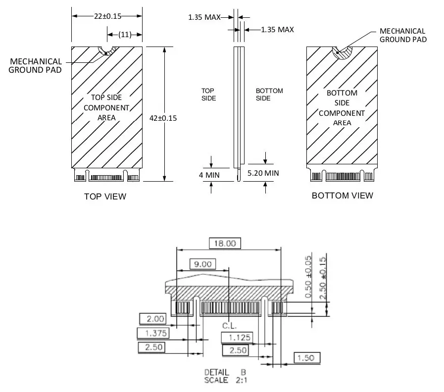
Note: the top side thickness is without the heat spreader. Heat spreader adds approximately 0.4mm to the thickness.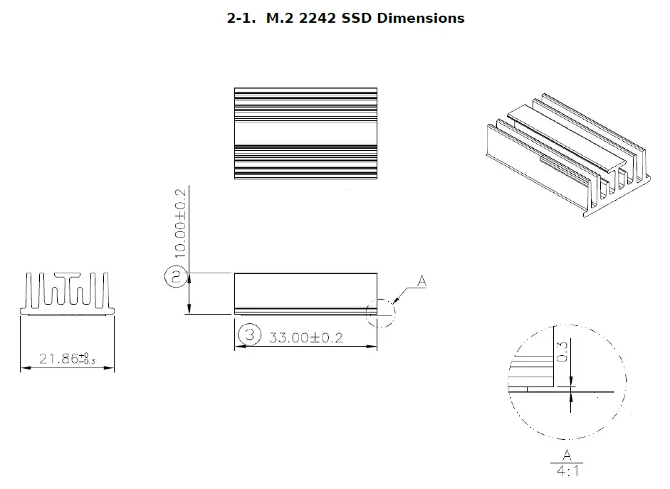
Interface Description
The following sections provide detailed information on the Cactus Technologies® Commercial M.2 SSD interface.
M.2 SSD Pin Assignments and Pin Type
The signal/pin assignments and descriptions are listed in Table 3-5. Note that the pinout definitions are from the perspective of the device.
Table 3-5. M.2 SSD Pin Assignments and Pin Type
| Pin # | Pin Name | Description | Pin # | Pin Name | Description |
| 1 | GND | 2 | 3.3V | 3.3V supply | |
| 3 | GND | 4 | 3.3V | ||
| 5 | PETn3 | 6 | Reserved | ||
| 7 | PETp3 | 8 | Reserved | ||
| 9 | GND | 10 | LED1# | LED for Drive activity | |
| 11 | PERn3 | 12 | 3.3V | ||
| 13 | PERp3 | 14 | 3.3V | ||
| 15 | GND | 16 | 3.3V | ||
| 17 | PETn2 | 18 | 3.3V | ||
| 19 | PETp2 | 20 | Reserved | ||
| 21 | GND | 22 | Reserved | ||
| 23 | PERn2 | 24 | Reserved | ||
| 25 | PERp2 | 26 | Reserved | ||
| 27 | GND | 28 | Reserved | ||
| 29 | PETn1 | 30 | Reserved | ||
| 31 | PETp1 | 32 | Reserved | ||
| 33 | GND | 34 | Reserved | ||
| 35 | PERn1 | 36 | Reserved | ||
| 37 | PERp1 | 38 | Reserved | ||
| 39 | GND | 40 | Reserved | ||
| 41 | PETn0 | 42 | Reserved | ||
| 43 | PETp0 | 44 | Reserved | ||
| 45 | GND | 46 | Reserved | ||
| 47 | PERn0 | 48 | Reserved | ||
| 49 | PERp0 | 50 | PERST# | PCIe reset | |
| 51 | GND | 52 | CLKREQ# | PCIe clock request | |
| 53 | REFCLKn | PCIe Reference Clock | 54 | PEWAKE# | Not used |
| 55 | REFCLKp | 56 | MFG_1 | Reserved for manufacturer use | |
| 57 | GND | 58 | MFG_2 | Reserved for manufacture use |
Cactus Technologies, Limited
| Pin # | Pin Name | Description | Pin # | Pin Name | Description |
| 59 |
M Key | 60 |
M Key | ||
| 61 | 62 | ||||
| 63 | 64 | ||||
| 65 | 66 | ||||
| 67 | DNU | 68 | SUSCLK | 32kHz clock input; not used | |
| 69 | NC | 70 | 3.3V | ||
| 71 | GND | 72 | 3.3V | ||
| 73 | GND | 74 | 3.3V | ||
| 75 | GND | 76 | |||
Electrical Specifications
The following table defines all D.C. Characteristics for the M.2 SSD products. Unless otherwise stated, conditions are:
Vcc = 3.3V ± 5%
Ta = -40°C to 85°C
Absolute Maximum Ratings
| Parameter | Symbol | MIN | MAX | Unit s |
| Storage Temperature | Ts | -55 | 100 | oC |
| Operating Temperature | TA | -40 | 85 | oC |
| Vcc with respect to GND | Vcc | -0.3 | 3.6 | V |
DC Characteristics
| Parameter | Symbol | MIN | MAX | Unit s |
| Input Voltage | Vin | -0.5 | Vcc + 0.5 | V |
| Output Voltage | Vout | -0.3 | Vcc + 0.3 | V |
| Input Leakage Current | ILI | -10 | 10 | uA |
| Output Leakage Current | ILO | -10 | 10 | uA |
| Input/Output Capacitance | CI/Co | 10 | pF |
| Parameter | Symbol | MIN | MAX | Unit s |
| Operating Current Idle Active | ICC | 210 1160 | mA |
AC Characteristics
Cactus Technologies® M.2 SSD products conforms to all AC timing requirements as specified in the PCI Express base specifications. Please refer to that document for details of AC timing for all operation modes of the device.
PCI Configuration
Cactus Technologies® M.2 SSD is a PCIe device. The following table shows the PCI Configuration Register values for this device:
| address | Bit[31:24] | Bit[23:16] | Bit[15:8] | Bit[7:0] |
| 00h | Device ID : 2263h | Vendor ID: 1E3Ah | ||
| 04h | Status: 0010h | Command | ||
| 08h | Class Code : 010802h Mass Storage Controller Non-volatile Memory NVM Express | Revision ID: 03h | ||
| 0Ch | BIST | Header Type: 00h | Latency Timer: | Cacheline Size |
| 10h |
Base Address Registers | |||
| 14h | ||||
| 18h | ||||
| 1Ch | ||||
| 20h | ||||
| 24h | ||||
| 28h | Cardbus CIS Pointer: N/A | |||
| 2Ch | Subsystem ID: 2263h | Subsystem Vendor ID: 1E3Ah | ||
| 30h | Expansion ROM Base Address | |||
| address | Bit[31:24] | Bit[23:16] | Bit[15:8] | Bit[7:0] |
| 34h | Reserved | Capabilities Pointer: N/A | ||
| 38h | Reserved | |||
| 3Ch | Max Lat: 00h | Min Gnt: 00h | Interrupt Pin | Interrupt Line |
PCI Express Capabilities
Cactus Technologies® Commercial grade M.2 SSD supported PCI Express capabilities are listed in the following table, please consult PCI Express Specifications for detailed explanation of the capabilities:
| Capability | Register | Description |
| PCI Express | Ver. 2; PCIe Endpoint; Slot not Implemented | |
| Device Capabilities | Max. payload size: 128 bytes; Phantom Function Supported: 0; Extended Tag Field supported: 5-bit; EndPoint L0s latency: unlimited; EndPoint L1 latency: unlimited; Role-based Error Reporting: supported; Slot Power Limit: 75W; Function Level Reset: supported | |
| Device Control | Set by host | |
| Device Status | Reported Status: Correctable Error Detected, Non-Fatal Error Detected, Fatal Error Detected, Unsupported Request Detected, Aux Power Detected, Transaction Pending | |
| Link Capabilities | 8GT/s, 4 lanes; ASPM L1 supported; L0s Exit Latency: 512ns – 1us; L1 Exit Latency: 4 – 8us; Clock Power Management: supported; Surprise Down Error Reporting: not supported; Data Link Layer Link Active Reporting: not supported; Link Bandwidth Notification: not supported; ASPM: supported | |
| Link Control | Set by host | |
| Link Status | Reported Status: Current Link Speed, Negotiated Link Width, Slot Clock Configuration | |
| Device Capabilities 2 | Completion Timeout Range: ABCD; Completion Timeout Disable: supported; LTR Mechanism: supported; OBFF: not supported; Extended Fmt Field: not supported | |
| Device Control 2 | Set by host | |
| Link Capabilities 2 | Supported Link Speeds: 2.5/5.0/8.0 GT/s; Crosslinks: not supported | |
| Link Control 2 | Set by host |
| Capability | Register | Description |
| Link Status 2 | Reported Status: Current De-emphasis Level, Equalization Complete, Equalization Phase 1 Successful, Equalization Phase 2 Successful, Equalization Phase 3 Successful, Link Equalization Request | |
| MSI | 64-bit address capable; Per vector masking supported | |
| MSI-X | MSI-X table size: 16; Per Vector Mask Bit | |
| Power Management | Complies with v3 of PCI Power Management Interface; DSI not required; PME# not supported; PME# assertion in D0, D1, D2, D3 not supported; Aux Current Required=0 | |
| Power Management Control/Status | Reported Status: No_Soft_Reset | |
| Extended Capabilities | Latency Tolerance Reporting | Capability version 1; Max Snoop Latency: 71680ns; Max No-Snoop Latency: 71680ns |
| L1 PM Substate | Version 1; PCI-PM L1.1, L1.2 supported; ASPM L1.1, L1.2 supported; L1 PM Substates supported; Port Common Mode Restore Time: 10us; Port T_Power_On Value: 10us | |
| L1 PM Substate Control 1 | Set by host | |
| L1 PM Substate Control 2 | Set by host | |
| Advanced Error Reporting | Capability version 2; Implemented Registers: Uncorrectable Error Status, Uncorrectable Error Mask, Uncorrectable Error Severity, Correctable Error Status, Correctable Error Mask, Advanced Error Capabilities and Control, Header Log | |
| Secondary PCI Express Extended Capability | Capability version 1; | |
| Link Control 3 | Set by host | |
| Lane Error Status | ||
| Lane Equalization Control | Set by host, one register per lane |
NVM Express Registers
The following sections describe the NVMe register contents of Cactus Technologies® Commercial grade M.2 SSD.
Controller Capabilities (CAP)
This 64-bit register indicates basic capabilities of the controller.
| Bit(s) | Name | Value | Description |
| 63:56 | Reserved | ||
| 55:52 | MPSMAX | 0 | Memory Page Size Max: 8192 |
| 51:48 | MPSMIN | 0 | Memory Page Size Min: 4096 |
| 47:46 | Reserved | ||
| 45 | BPS | 0 | Boot Partition: not supported |
| 44:37 | CSS | 1 | Command Set Supported: NVM command set |
| 36 | NSSRS | 0 | NVMe Subsystem Reset Supported: Yes |
| 35:32 | DSTRD | 0 | Doorbell Stride: 4 bytes, this indicates there is no gap between doorbells registers |
| 31:24 | TO | 78h | TimeOut for CSTS.RDY to switch states: 120s |
| 23:19 | Reserved | ||
| 18:17 | AMS | 00 | Arbitration Mechanism Supported: Round robin |
| 16 | CQR | 1 | Contiguous Queue Required. I/O submission and completions queues must be physically contiguous. |
| 15:0 | MQES | 3FFFh | Max. Queue Entries Supported for I/O queues: 16384 |
Version (VS)
This 32-bit register indicates the NVMe Specification supported by the device. Cactus Technologies® Commands grade M.2 SSD supports NVMe Specification v1.3.
| Bit(s) | Name | Value | Description |
| 31:16 | MJR | 0001h | Major Version Number: 1 |
| 15:8 | MNR | 03h | Minor Version Number: 3 |
| 7:0 | TER | 0 | Tertiary Version Number: 0 |
Interrupt Mask Set (INTMS)
This 32-bit register is used to mask interrupts if legacy or MSI interrupts are used, this register is not used if MSI-X interrupts are used.
| Bit(s) | Name | Value | Description |
| 31:0 | IVMS | Interrupt Vector Mask Set. Each bit that is set to ‘1’ masks the corresponding interrupt vector. |
Interrupt Mask Clear (INTMC)
This 32-bit register is used to clear interrupt masks if legacy or MSI interrupts are used, this register is not used if MSI-X interrupts are used.
| Bit(s) | Name | Value | Description |
| 31:0 | IVMC | Interrupt Vector Mask Clear. Each bit that is set to ‘1’ clears the corresponding interrupt vector mask. |
Controller Configuration (CC)
This 32-bit register is written by the host to modify settings for the drive controller.
| Bit(s) | Name | Value | Description |
| 31:24 | Reserved | ||
| 23:20 | IOCQES | I/O Completion Queue Entry Size | |
| 19:16 | IOSQES | I/O Submission Queue Entry Size | |
| 15:14 | SHN | Shutdown Notification | |
| 13:11 | AMS | Arbitration Mechanism Selected | |
| 10:7 | MPS | Memory Page Size | |
| 6:4 | CSS | I/O Command Set Selected | |
| 3:1 | Reserved | ||
| 0 | EN | Enable. Host writes ‘1’ to this bit to enable the device to start processing commands. |
Controller Status (CSTS)
This 32-bit register provides status information of the drive controller.
| Bit(s) | Name | Value | Description |
| 31:6 | Reserved | ||
| 5 | PP | Process Paused. When set to ‘1’, it indicates the drive controller has stopped processing commands | |
| 4 | NSSRO | NVM Subsystem Reset Occurred. When set to ‘1’, it indicates a reset has occurred while powered up. | |
| 3:2 | SHST | Shutdown Status. 00b: Normal, no shutdown requested; 01b: shutdown processing occuring; 10b: shutdown processing complete; 11b: reserved | |
| 1 | CFS | Controller Fatal Status. A value of ‘1’ indicates a fatal controller error has occurred. | |
| 0 | RDY | Ready. A value of ‘1’ indicates the drive controller is ready to accept commands |
NVM Subsystem Reset (NSSR)
Host writes a value of 4E564D65h to this register to request an NVM Subsystem Reset. A write of any other values to this register has no effect. A read of this register always returns zeroes. This register is supported only if the NSSRS bit is set.
Admin Queue Attributes (AQA)
This 32-bit register contains attributes for the Admin Submission and Completion queues.
| Bit(s) | Name | Value | Description |
| 31:28 | Reserved | ||
| 27:16 | ACQS | Admin Completion Queue Size: 32 | |
| 15:12 | Reserved | ||
| 11:0 | ASQS | Admin Submission Queue Size: 32 |
Admin Submission Queue Base Address (ASQ)
This 64-bit register is written by the host to set the Admin Submission Queue Base Address.
Admin Completion Queue Base Address (ACQ)
This 64-bit register is written by the host to set the Admin Completion Queue Base Address.
Controller Buffer Memory Location (CMBLOC)
This 32-bit register contains the location of the drive’s Controller Buffer Memory. If the Controller Buffer Memory Size (CMBSZ) register content is zero, this register is reserved.
| Bit(s) | Name | Value | Description |
| 31:12 | OFST | Offset. This indicates the offset of the Controller Buffer Memory in multiples of the size unit indicated in CMBSZ. This value is 4KB aligned. | |
| 11:3 | Reserved | ||
| 2:0 | BIR | Base Indicator Register. This indicates the Base Address Register (BAR) that contains the Controller Buffer Memory. |
Controller Buffer Memory Size (CMBSZ)
This 32-bit register defines the size of the drive’s Controller Buffer Memory.
| Bit(s) | Name | Value | Description |
| 31:12 | SZ | 0 | Size. This indicates the size of the Controller Buffer Memory in multiples of the size unit indicated in bit[2:0]. Cactus Technologies® M.2 SSD does not support Controller Buffer Memory. |
| 11:8 | SZU | 0 | Size Unit. |
| 7:5 | Reserved | ||
| 4 | WDS | 0 | Write Data Support. All write data must be transferred from host memory. |
| 3 | RDS | 0 | Read Data Support. All read data must be transferred to host memory. |
| 2 | LISTS | 0 | PRP SGL Support. All PRP and SGL lists must be placed in host memory. |
| 1 | CQS | 0 | Completion Queue Support. All Completion Queues must be placed in host memory. |
| 0 | SQS | 0 | Submission Queue Support. All Submission Queues must be placed in host memory. |
Boot Partition Info (BPINFO)
Cactus Technologies® M.2 SSD does not support Boot Partition, this register will read back zeroes.
Boot Partition Read Select (BPRSEL)
Cactus Technologies® M.2 SSD does not support Boot Partition, this register will read back zeroes.
Boot Partition Memory Buffer Location (BPMBL)
Cactus Technologies® M.2 SSD does not support Boot Partition, this register will read back zeroes.
Submission Queue y Tail Doorbell (SQyTDBL)
This 32-bit register defines the Tail entry pointer for submission queue y. There is one tail doorbell register for each submission queue. The register for queue y is located at (1000h + ((2y)*(4<<CAP.DSTRD))).
| Bit(s) | Name | Value | Description |
| 31:16 | Reserved | ||
| 15:0 | SQT | Submission Queue Tail |
Completion Queue y Head Doorbell (CQyHDBL)
This 32-bit register defines the Head entry pointer for completion queue y. There is one head doorbell register for each completion queue. The register for queue y is located at (1000h + ((2y+1)*(4<<CAP.DSTRD))).
| Bit(s) | Name | Value | Description |
| 31:16 | Reserved | ||
| 15:0 | CQH | Completion Queue Head |
Identify Command
The Identify command is an Admin command that retrieves information about the NVM subsystem. The returned structure is 4096 bytes and the following section describes the contents of this structure in Cactus Technologies® Commercial grade M.2 SSDs.
Identify Controller Data Structure
| Byte(s) | Name | Value | Description |
| 1:0 | VID | 1E3Ah | PCI Vendor ID. This is PCISIG assigned Vendor ID for Cactus Technologies® |
| 3:2 | SSVID | 1E3Ah | PCI Subsystem ID. |
| 23:4 | SN | varies | This field returns product specific serial number. |
| 63:24 | MN | Fixed | This field returns manufacturer’s name. For this product, the returned string is: CactusFlashCard |
| 71:64 | FR | varies | Firmware version. |
| 72 | RAB | 6 | Recommended Arbitration Burst size in bytes. |
| 75:73 | IEEE | 0 | IEEE OUI Identifier. Not applicable for this product. |
| 76 | CMIC | 0 | Controller Multipath I/O and Namespace Sharing Capacbilities: Single Port, Single Controller, PCI function. |
| 77 | MDTS | 5 | Max. Data Transfer Size: 2^5 x MPSMIN |
| 79:78 | CNTLID | 1 | Controller ID. |
| 83:80 | VER | 10300h | Version: NVM Express 1.30 |
| 87:84 | RTD3R | 7A120h | RTD3 Resume Latency. Resume time from Runtime D3 : 500ms |
| 91:88 | RTD3E | 1E8480h | RTD3 Entry Latency. Latency to enter Runtime D3: 2s |
| 95:92 | OAES | 200h | Optional Asynchronous Events Supported: Firmware Activation Notices supported |
| 99:96 | CTRATT | 0 | Controller Attributes: 128-bit host identifier not supported; Non-operational State Power State Permissive Mode not supported |
| 239:100 | Reserved | ||
| 254:240 | Reserved | ||
| 255 | 0 | Management Endpoint Capabilities: none | |
| 257:256 | OACS | 17h | Optional Admin Command Support Security Send & Receive commands: supported Format NVM command: supported Firmware commit and Download: supported Namespace management & Attachment commands: not supported Device Self-test: supported |
| 258 | ACL | 4 | Abort Command Limit |
| 259 | AERL | 7 | Asynchronous Event Request Limit |
| 260 | FRMW | 14h | Firmware Updates: Firmware Slot 1 Rd/Wr; 2 firmware slots; firmware activation without reset supported |
| 261 | LPA | Fh | Log Page Attributes: SMART Log page per namespace supported, Command Effects Log page supported, Extended data for Get Log Page supported, Telemetry log page supported |
| 262 | ELPE | 255 | Error Log Page Entries |
| 263 | NPSS | 4 | Number of Power States Support |
| 264 | AVSCC | 0 | Admin Vendor-Specific Command Configuration: Vendor Specific |
| 265 | APSTA | 1 | Autonomous Power State Transition Attributes: Autonomous Power State Transition supported |
| 267:266 | WCTEMP | 348 | Warning Composite Temperature Threshold: 348K (75C) |
| 269:268 | CCTEMP | 353 | Critical Composite Temperature Threshold: 353K (80C) |
| Byte(s) | Name | Value | Description |
| 271:270 | MTFA | 50 | Max. Firmware Activation Time: 5s |
| 275:272 | HMPRE | 0 | Host Memory Buffer Prefer Size: HBM not supported |
| 279:276 | HMMIN | 0 | Host Memory Buffer Min. Size: HBM not supported |
| 295:280 | TNVMCAP | 0 | Total NVM Capacity: Not reported as Namespace Mangement & Attachment commands are not supported |
| 311:296 | UNVMCAP | 0 | Unallocated NVM Capacity: not reported |
| 315:312 | RPMBS | 0 | Replay Protected Memory Block Support: not supported |
| 317:316 | EDSTT | 5 | Extended Device Self-test Time: 5 mins |
| 318 | DSTO | 1 | Device Self-test Option: one device self-test operation at a time |
| 319 | FWUG | 0 | Firware Update Granularity: no information provided |
| 321:320 | KAS | 0 | Keep Alive Support: not supported |
| 323:322 | HCTMA | 1 | Host Controlled Thermal Management Attribute: supported |
| 325:324 | MNTMT | 303 | Min. Thermal Management Temperature: 30C |
| 327:326 | MXTMT | 348 | Max. Thermal Management Temperature: 75C |
| 331:328 | SANICAP | 2 | Sanitize Capabilities: Block Erase Sanitize supported |
| 511:332 | Reserved | ||
| 512 | SQES | 66h | Submission Queue Entry Size. Required: 64, Max: 64 |
| 513 | CQES | 44h | Completion Queue Entry Size. Required: 16, Max: 16 |
| 515:514 | MAXCMD | 0 | Max Outstanding Command: not applicable |
| 519:516 | NN | 1 | Number of Namespaces: 1 |
| 521:520 | ONCS | 5Fh | Optional NVM Command Support: Compare Command: supported Write Uncorrectable Command: supported Dataset Management Command: supported Write Zeroes Command: supported Save and Select Fields: supported Reservations: not supported Timestamp: supported |
| 523:522 | FUSES | 0 | Fused Operation Support: Fused Compare and Write operation not supported |
| 524 | FNA | 0 | Format NVM Attributes: Format applies to single namespace, Crypto and user data erase applies to single namespace, Cryptoerase not supported as part of Secure Erase |
| 525 | VWC | 7 | Volatile Write Cache: present |
| 527:526 | AWUN | 0 | Atomic Write Unit Normal: size of write unit guaranteed to be written atomically during normal operation |
| 529:528 | AWUPF | 0 | Atomic Write Unit Power Fail: size of write unit guaranteed to be written atomically during power fail or error condition |
| 530 | NVSCC | 0 | NVM Vendor Specific Command Configuration: Vendor specific |
| 531 | Reserved | ||
| 533:532 | ACWU | 0 | Atomic Compare & Write Unit: size of write unit guaranteed to be written atomically during a fused compare and write operation |
| 535:534 | Reserved | ||
| 539:536 | SGLS | 0 | SGL Support: not supported |
| 767:540 | Reserved | ||
| 1023:768 | SUBNQN | NVM Subsystem NVMe Qualified Name: not applicable |
| Byte(s) | Name | Value | Description |
| 2047:1024 | Reserved | ||
| 2079:2048 | PSD0 | Power State 0 Descriptor: Max Power (MP): 9W Non-Operational State (NOPS): I/O commands operational Entry Latency (ENLAT): 0 Exit Latency (EXLAT): 0 Relative Read Throughput (RRT): 0 Relative Read Latency (RRL): 0 Relative Write Throughput (RWT): 0 Relative Write Latency (RWL): 0 Idle Power (IDLP): – Active Power (ACTP): – | |
| 2111:2080 | PSD1 | Power State 1 Descriptor: Max Power (MP): 4.6W Non-Operational State (NOPS): I/O commands operational Entry Latency (ENLAT): 0 Exit Latency (EXLAT): 0 Relative Read Throughput (RRT): 1 Relative Read Latency (RRL): 1 Relative Write Throughput (RWT): 1 Relative Write Latency (RWL): 1 Idle Power (IDLP): – Active Power (ACTP): – | |
| 2143:2112 | PSD2 | Power State 2 Descriptor: Max Power (MP): 3.8W Non-Operational State (NOPS): I/O commands operational Entry Latency (ENLAT): 0 Exit Latency (EXLAT): 0 Relative Read Throughput (RRT): 2 Relative Read Latency (RRL): 2 Relative Write Throughput (RWT): 2 Relative Write Latency (RWL): 2 Idle Power (IDLP): – Active Power (ACTP): – | |
| 2175:2144 | PSD3 | Power State 3 Descriptor: Max Power (MP): 0.045W Non-Operational State (NOPS): I/O commands non- operational Entry Latency (ENLAT): 2000us Exit Latency (EXLAT): 2000us Relative Read Throughput (RRT): 3 Relative Read Latency (RRL): 3 Relative Write Throughput (RWT): 3 Relative Write Latency (RWL): 3 Idle Power (IDLP): – Active Power (ACTP): – |
SMART Reporting
Cactus Technologies® Commands M.2 SSD supports SMART attribute reporting in the SMART Log Page using the Get Log Page Admin command. The attributes reported are shown below.
SMART Attributes
The following attributes are reported in the SMART Log page:
| Attribute | Description |
| Critical Warning | Bit 0: if set to ‘1’, this indicates available spare has fallen below threshold Bit 1: if set to ‘1’, this indicates temperature has exceeded high temperature threshold or dropped below low temperature threshold Bit 2: if set to ‘1’, this indicates excessive media error Bit 3: if set to ‘1’, this indicates the drive is in read only mode Bit[7:4]: reserved |
| Temperature | Temperature in Kelvin |
| Available Spare | Percentage remaining spares |
| Available Spare Threshold | Warning flag is set if remaining spares drops below this threshold percentage |
| Percentage Used | This is a vendor specific estimation of the percentage life used for the device |
| Data Units Read | Number of 512bytes units read; each count represents 1000 units |
| Data Units Written | Number of 512bytes units written; each count represents 1000 units |
| Host Read Commands | Number of host read commands processed |
| Host Write Commands | Number of host write commands processed |
| Controller Busy Time | The amount of time the drive is busy processing I/O commands; the unit is in minutes |
| Power Cycles | Number of power cycles |
| Power On Hours | Number of Power On Hours |
| Unsafe Shutdowns | The number of power loss without prior Shutdown notification. |
| Attribute | Description |
| Media and Data Integrity Errors | Number of uncorrectable data errors |
| Number of Error Information Log Entries | Number of Error Information Log Entries over the product’s life |
| Warning Composite Temperature Time | Amount of time in minutes that the drive is in operation above the Warning Temperature Threshold but below the Critical Temperature Threshold |
| Critical Composite Temperature Time | Amount of time in minutes that the drive is in operation above the Critical Temperature Threshold |
Device Features
Features supported by Cactus Technologies® Commercial M.2 SSD are reported using the Get Features Admin command. The supported features are listed below:
| Identifier | Name | Value | Description |
| 1 | Arbitration | 6h | This feature controls command arbitration. Bit[31:24]: High Priority Weight (HPW). This defines the number of commands that can be executed from the High Priority service class in each arbitration round. Bit[23:16]: Medium Priority Weight (MPW). This defines the number of commands that can be executed from the Medium Priority service class in each arbitration round. Bit[15:08]: Low Priority Weight (LPW). This defines the number of commands that can be executed from the Low Priority service class in each arbitration round. Bit[7:3]: Reserved Bit [2:0]: Arbitration Burst (AB). This indicates the max. number of commands the controller can launch at one time from a Submission Queue. Value specified is 2^n. |
| 2 | Power Management | 0 | This feature is used by the host to control the device power state. The returned content reflects the current power state attributes. Bit[31:8]: Reserved Bit [7:5]: Workload Hint (WH). This field indicates the type of workload expected; this is set by the host with the Set Feature command. Bit[4:0]: Power State (PS). This field indicates the power state the device should transition to. This is set by the host with the Set Feature command. |
| Identifier | Name | Value | Description |
| 3 | LBA Range Type | 0 | This field always returns zeroes on reads. |
| 4 | Temperature Threshold | 15Ch | Bit[31:22]: Reserved Bit[21:20]: Threshold Type Select (THSEL). 00b – over temperature threshold; 01b – Under temperature threshold; 10b, 11b – Reserved. Bit[19:16]: Threshold Temperature Select (TMPSEL). 0000b – composite temperature; 0001b – 1000b : binary coded value of temperature sensor; 1001b – 1111b: Reserved Bit[15:0]: Temperature Threshold (TMPTH). Value indicated in °K. |
| 5 | Error Recovery | 0 | This field reflects Error Recovery options as set by the host. Bit[31:17]: Reserverd Bit[16]: Deallocated or Unwritten Logical Block Error Enable (DULBE) – not enabled Bit[15:0]: Time Limited Error Recovery (TLER). This indicates a limited retry timeout value in units of 100ms. |
| 6 | Volatile Write Cache | 1 | Volatile Write Cache Enable (WCE). This field reflects the state of Volatile Write Cache as set by the host. Bit[31:1]: Reserved Bit[0]: If set, Volatile Write Cache is enabled. |
| 7 | Number of Queues | 000F000Fh | Bit[31:16]: Number of I/O Completion Queue Allocated (NCQA). Bit[15:0]: Number of I/O Submission Queue Allocated (NSQA). These values reflect the max. number of queues the controller can support. |
| 8 | Interrupt Coalescing | 0 | Bit[31:16]: Reserved Bit[15:8]: Aggregation Time (TIME). Max. time in 100us units that the controller can delay an interrupt. 0 indicates no delay. Bit[7:0]: Aggregation Threshold (THR). This indicates the min. number of completion queue entries to aggregrate before interrupting the host, value is n+1. |
| Identifier | Name | Value | Description |
| 9 | Interrupt Vector Configuration | 0 | This field returns the status of Interrupt Vector Configuration as set by the host. Bit[31:17]: Reserved Bit[16]: Coalescing Disable (CD). If set to 1, interrupt coalescing is disabled for the Interrupt Vector indicated in bit[15:0]. Bit[15:0]: Interrupt Vector (IV). This field indicates the Interrupt Vector applicable to this configuration. |
| 10 | Write Atomicity Normal | 0 | This field reflects the opertions of AWUN and NAWUN parameters as set by the host. Bit[31:1]: Reserved Bit[0]: Disable Normal (DN). If set to 1, controller are not required to honor AWUN and NAWUN. |
| 11 | Asynchronous Event Configuration | 200h | This field controls asynchronous event reporting as set by the host. Bit[31:10]: Reserved Bit[9]: Firmware Activation Notice. If set, firmware activation notices are to be sent to the host. Bit[8]: Namespace Attribute Notice. If set, namespace attribute change event notices are to be sent to the host. Bit[7:0]: SMART Critical Warning. If set, each corresponding critical warning bit in SMART Log will trigger notice to the host. |
| 12 | Autonomous Power State Transition | 0 | This feature reports power state transition settings. Bit[31:1]: Reserved. Bit[0]: Autonomous Power State Transition Enable (ASPTE). If cleared, Autonomous Power State Transition is disbaled. If set, transition attributes for each power state is returned in the Autonomous Power State Transition Structure. |
Ordering Information
Model KDXFY-270PM6
Where: X is drive capacities:
128G —————- 128GB
256G —————- 256GB
512G —————- 512GB
Where: Y is the temperature grade
Blank ————— standard temp. (comes with heat spreader)
I ———————- extended temp. (comes with heat sink)
Example:
1. KD128GF-270PM6 ————————————— 128G standard temp. SSD
2. KD256GFI-270PM6 ————————————– 256G extended temp. SSD
Appendix A.Technical Support Services
Email: [email protected]
Appendix B.Cactus Technologies® Worldwide Sales Offices
Email: [email protected]
Email: [email protected]
Limited Warranty
- WARRANTY STATEMENT
Cactus Technologies® warrants its Industrial Grade products only to be free of any defects in materials or workmanship that would prevent them from functioning properly for two years from the date of purchase or when rated TBW is exceeded, whichever occurs first. This express warranty is extended by Cactus Technologies® Limited to customers of our products. - GENERAL PROVISIONS
This warranty sets forth the full extent of Cactus Technologies® responsibilities regarding the Cactus Technologies® Commercial Grade Flash Storage Products. Cactus Technologies®, at its sole option, will repair, replace or refund the purchase price of the defective product. Cactus Technologies® guarantees our products meet all specifications detailed in our product manuals. Although Cactus Technologies® products are designed to withstand harsh environments and have the highest specifications in the industry, they are not warranted to never have failure and Cactus Technologies® does not warranty against incidental or consequential damages. Accordingly, in any use of products in life support systems or other applications where failure could cause injury or loss of life, the products should only be incorporated in systems designed with appropriate redundancy, fault tolerant or backup features. - WHAT THIS WARRANTY COVERS
For products found to be defective, Cactus Technologies® will have the option of repairing, replacing or refunding the purchase price the defective product, if the following conditions are met:- The defective product is returned to Cactus Technologies® for failure analysis as soon as possible after the failure occurs.
- An incident card filled out by the user, explaining the conditions of usage and the nature of the failure, accompanies each returned defective product.
- No evidence is found of abuse or operation of products not in accordance with the published specifications, or of exceeding maximum ratings or operating conditions.
All failing products returned to Cactus Technologies® under the provisions of this limited warranty shall be tested to the product’s functional and performance specifications. Upon confirmation of failure, each product will be analyzed, by whatever means necessary, to determine the root cause of failure. If the root cause of failure is found to be not covered by the above provisions, then the product will be returned to the customer with a report indicating why the failure was not covered under the warranty.
This warranty does not cover defects, malfunctions, performance failures or damages to the unit resulting from use in other than its normal and customary manner, misuse, accident or neglect; or improper alterations or repairs. Cactus Technologies® Limited may repair or replace, at its discretion, any product returned by its customers, even if such product is not covered under warranty, but is under no obligation to do so.
RECEIVING WARRANTY SERVICE
According to Cactus Technologies® warranty procedure, the defective products should be returned only with prior authorization from Cactus Technologies® Limited. Please contact Cactus Technologies® Customer Service department ([email protected]) with the following information: product model number and description, nature of the defect, conditions of use, proof of purchase and purchase date. If approved, Cactus Technologies® will issue a Return Material Authorization or Product Repair Authorization number and instructions to ship the product back to us for service.


 User Manual")


