
![]()

Residential Energy Storage User Manual
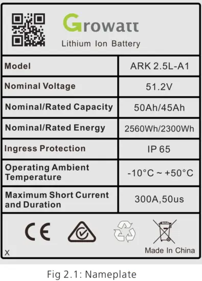
ARK 2.5L-A1 Battery System
About this Document
This document describes the installation, electrical connection, operation, commission, maintenance, and troubleshooting of the ARK 2.5L-A1 Battery System (hereafter simply put ARK 2.5L-A1). Before installing and operating ARK-2.5L-A1, ensure that you are familiar with product features, functions, and safety precautions provided in this document.
| Symbol | Description |
| Indicates a potentially hazardous situation, if not avoided, could result in serious injury or death. |
Product Overview
1.1 Intended Use
Each ARK 2.5L-A1 consists of 50Ah cells which form a 51.2V voltage battery module and sixteen serial connections (1P16S). Two to ten ARK 2.5L-A1 can be connected in parallel and extend the capacity and power of the energy storage system. The same type of cell and the same software version of the PACK can be used in parallel. Specifically, the ARK battery system powers the loads through PCS at nighttime without solar; when solar becomes available during daytime, solar energy powers the loads as a priority and stores residual solar power into the ARK batter system.
1.2 Appearance
ARK-2.5L-A1 consists of a battery module (including cell and mechanical parts), battery management system (BMS) as well as power and communication terminals. The product appearance is shown as below.
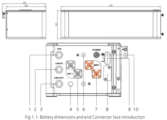
| Location | Port | Function |
| 1 | Communication interface | PCS CAN communication |
| 2 | LINK-IN CAN communication | |
| 3 | LINK-OUT CAN communication | |
| 4 | Safety vent | Balance air pressure |
| 5 | Negative terminal | Stands for PACK anode output |
| 6 | GND terminal | The terminal connects to ground |
| 7 | Positive terminal | Stands for PACK cathode output |
| 8 | USB interface | USB interface for system upgrade |
| 9 | Lamp panel | SOC and status display panel |
| 10 | Power button | Starting up |
| No. | Name | Color | Description |
| A | LED 1 | Blue | 0%-25% |
| B | LED 2 | Blue | 26%-50% |
| C | LED 3 | Blue | 51%-75% |
| D | LED 4 | Blue | 76%-100% |
| E | RUN | Green | Normal operation |
| F | ALM | Red | Failure or protection status |
1.3 Working Principle and Function
ARK 2.5L-A1 is an energy storage unit composed of electrochemical cells, switch button, battery management unit, power and signal terminals, and mechanical parts. It features
better charge and discharge performance, a more precise status monitor, longer cycle life, and less self-discharge loss than other batteries. Two to ten PACKs connected in parallel increase the capacity and power of the battery system; the whole battery system communicates to Power Conversion System (PCS) via CAN.
- Monitoring: voltage, current and temperature detection of both single cells and PACK.
- Protection and Alarm: protection and alarm when overvoltage, under-voltage, over-current, over-temperature or under temperature occurs. See Appendix I for the details.
- Report: report all alarm and status data to PCS.
- Parallel connection: support two to ten PACKs in parallel connection.
- Passive balance function.
- Power off triggered by fault: PACK and PCS communication lost for 25 minutes or under-voltage protection for 30 minutes.
Safety
Safety information contains in this section must be observed at all times when working on or with batteries. For safety, installers are responsibility to familiarize themselves with
this manual and all warnings before installation.
2.1 Basic security
The PACK has been designed and tested in strict rules with international safety certification requirements. Read all safety instructions carefully before any work and obey the rules at all times when working on or with the PACK. Growatt shall not be liable for any consequence caused by the violation of the following:
- Damage occurred during transportation
- Incorrect transportation, storage, installation and use, or customer fails to convey the correct information about transportation, storage, installation and use to terminal
customers. - Non-professional installation
- Failure to obey the rules of this operation instructions and safety precautions in this document
- Unauthorized modifications or removal of the software package
- PACK tamper label is damaged or product with any part missing (except the authorized dissemble parts).
- Operation in extreme environments which are not allowed in this document
- Repair, disassemble, or change PACKs without authorization and cause failure.
- Damage to shell labels or modifies date of production.
- PACK fail to be charge for more than six months.
- Damages due to force majeure (such as lightning, earthquakes, fire, and storms)
- Warranty expiration.
2.2 Safety Precautions
2.2.1 Environment requirements
Do not expose the battery to temperatures above 50℃ or heat sources.
Do not install or use the battery in wet locations, moisture, corrosive gases or liquids, such as a bathroom.
Do not expose the battery to direct sunlight for extended periods of time.
Place battery in safe place away from children and animals.
Battery power terminals shall not touch conductive objects such as wires.
Do not dispose the batteries in fire, which may cause an explosion.
PACK shall not come in contact with liquids.
2.2.2 Operation Precautions
Do not touch the PACK with wet hands.
Do not disassemble the PACK without permission
Do not crush, drop or puncture the PACK and battery.
Dispose the batteries according to local safety regulations.
Store and recharge battery in accordance with this manual.
Ensure the connection of ground wire reliable.
Remove all metal objects such as watches and rings that could cause a short-circuit before installation, replacement and maintenance.
The Pack shall be repaired, replaced or maintained by skilled personal that has been recognized.
When storing or handling batteries ,do not stack batteries without package.
Do not broke the battery, the released electrolyte may be toxic and is harmful to skin and eyes.
Packaged batteries should not be stacked more than specified number stipulated on the packing case.
Do not use damaged, failed or deformed batteries, which may lead to high temperature or even dangerous accidents. Continued operation of damaged battery may result in
electrical shock, fire or even worse.
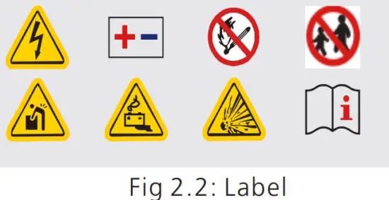
2.3 Warning Labels
| Symbols | Description |
 | Do not dispose of in the trash |
 | The lithium-ion battery can be recycled |
 | Certification in the European Union area |
 | Electric shock hazard |
 | Explosive gas |
 | Alternating Current (AC) |
 | Heavy enough to cause severe injury |
 | Keep the Pack away from children |
| Make sure the battery polarity well connected | |
 | Do not expose to fire |
 | Operate as the Manual |
![]() WARNING
WARNING
- Do not disassemble or alter the PACK to avoid heat , explosion or fire.
- Do not use the PACK beyond specified conditions.It might cause heat generation, damage,or deterioration of its performance.
- Do not throw, drop, hit, drive a nail in, or stamp on the PACK.It may cause heat generation, explosion,or fire.
- In case of electrolyte leakage, keep leaked electrolytes away from contact with eyes or skin. immediately clean with water and seek help from a doctor.
- Do not put the PACK into a fire. Do not use it or leave it on a place near fire, heaters, or high-temperature sources.It may cause over-temperature, explosion or fire.
- Do not submerge the PACK in water,or wet the product.It may cause heat generation, explosion,or fire.
- Do not reversely connect the PACK positive(+)and negative(-)terminal.
- Do not short circuit by letting the PACK terminals(+and -)contact a wire or any metal.
- The unit is heavy enough to cause severe injury.
- Keep out of reach of children or animals.
Note: When the ambient temperature is between -10 ℃ and 0℃, the maximum charging current of the battery is 2.5A.
2.4 Emergency Responses
The manufacturer takes foreseeable risk scenarios into consideration and is designed to reduce hazards and dangers. However, if the following situation occurs, do as below:
| Situation Occurs | Description and action need |
| Leakage | Avoid touch of leaking liquid or gas. If you touch the leaking electrolyte, do as below immediately. Inhalation: Evacuate the contaminated area, and seek medical help. Eye contact: Rinse eyes with flowing water for 15 minutes, and seek medical help. Skin contact: Rinse contacted area thoroughly with soap and water, and seek medical help. Ingestion: Vomiting, and seek medical help. |
| Fire | It’s hard for PACK systems ignite spontaneously. If the PACK has caught a fire, do not try to extinguish the fire but evacuate people immediately. |
| Wet Packs | If PACK is flooded or submerged, do not access it. Contact Growatt or distributor for technical assistance immediately. |
| Damaged PACKS | Damaged PACKS are dangerous and must be handled with special attention. They are no longer suitable for use and may cause danger to people. If the PACK damaged, stop use it and then contact the Growatt or distributor. |
Storage and Transportation
3.1 Storage Requirements
- Place the PACK follow the identification on the packing case during storage.
- Do not put the PACK upside down or sidelong.
- The defective PACK needs to be separated from other PACKs.
- The storage environment requirements are as follows:
Install the PACK in a dry and clean place with proper ventilation.
The storage temperature for a short week is between -30°C to 60℃.
If you store the PACK over a long period of six months, the storage temperature is between-20°C to 50°C, relative humidity: 5%~95%RH.
Place the PACK away from corrosive and organic substances (including gas exposure).
Free from direct exposure to sunlight and rain .
At least two meters away from heat sources (such as a radiator).
Free from exposure to intensive infrared radiation.
Note: If a PACK is useless for six months, it needs to be recharged.
Recharge procedures
- Identify the PACK that needs recharging;
- Refer to the quick installation guide, and complete the installation and wire connection.
Ensure PACK in off status during all the steps. - Set the power system as “CC=25A, CV=55.8V” , activate the PACK and start recharging.
- Recharge until LED2 flicks.
- Having completed recharge, leave the circuit open for five minutes before checking the voltage. If the voltage is not less than 52V, the recharge is successful.
3.2 Transportation Requirement
PACK has been certified in UN38.3 (Section 38.3 of the sixth Revised Edition of the Recommendations on the Transport of Dangerous Goods: Manual of Tests and Criteria)
and SN/T 0370.2-2009 (Part 2: Performance Test of the Rules for the Inspection of Packaging for Exporting Dangerous Goods). PACK is classified as category 9 dangerous
goods.
- The PACK shall not be transported with other inflammable, explosive or toxic substances.
- Ensure the original Package and label complete and recognizable.
- Prohibit direct exposure to sunlight, rain, condensing water caused by temperature difference and mechanical damages.
- Prohibit to pile up more than six PACKs.
- There will be a drop in capacity during transportation and storage.
- Transportation temperature is between-20°C to 50°C, relative humidity: 5%~95%RH.
Installation
 WARNING | Ø Ensure to read the Guidance before installation in order to understand product information and safety cautions; Ø Operators should be well-trained technicians and fully understand the a whole photovoltaic system, grid network, the working principle and national regional standards; Ø Installers must use insulating tools and wear safety equipment; Ø Device damages caused by failure to comply with storage, transportation, installation and use requirements specified in Guidance are not coved by the Warranty. |
4.1 Installation environment
The ambient temperature for the installation of the battery system shall be above -10℃, below 50℃, and the humidity shall between 5% and 95%.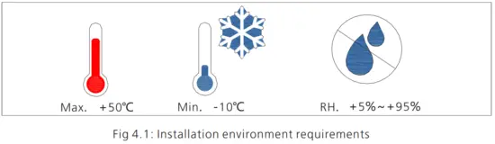
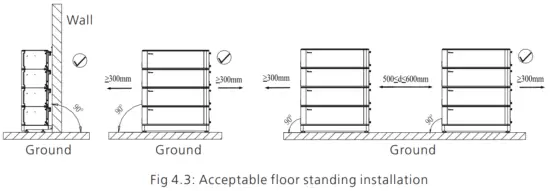
4.2 Basic installation requirements
Ø The PACK can be installed indoors or outdoors. The following conditions are allowed: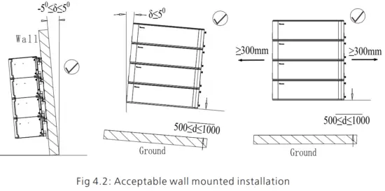
WARNING | Do not place the PACK upside down. |
Ø Build sun& rain shade to avoid direct exposure to the sunlight and rain.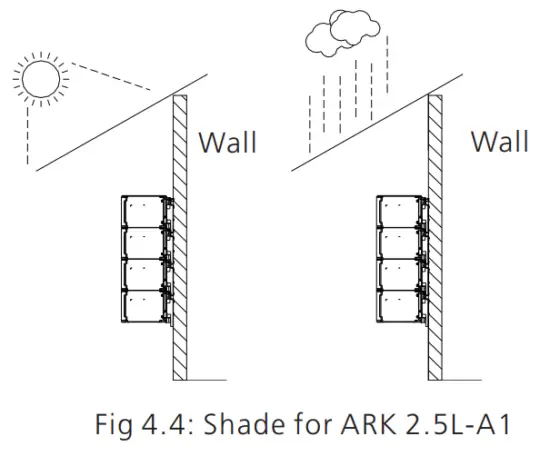
4.3 Installation Required Tools
The following tools are required to install the PACK: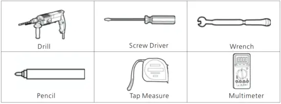
It is recommended to wear the following safety gear when dealing with the PACK.
4.4 Installation Procedures
Pre-installation Check
| Check the package | Check the PACK package before open it. If any abnormity is detected, do not open the Package and contact your distributor. |
| Check the power | Check and confirm the PACK is powered off before installation. |
| Check deliverable | Check the quantity of all parts inside according to the package list. If there is any part missing or damaged, please contact your distributor. |
Check the ARK-2.5L-A1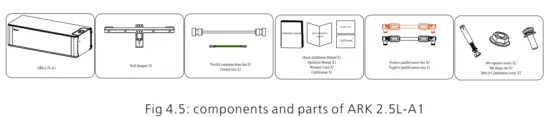
Check the accessories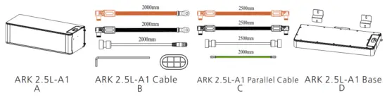
| Installation Method | Compound Mode |
| Standard Wall-Mounted Installation | A+B |
| Standard floor installation | A+B+D |
| Wall-Mounted Battery system stacked in two line | A+B+C |
| Floor installation battery system stacked in two line | A+B+C+D*2 |
Wall Mounted Installation
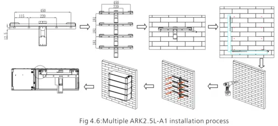
Step 1: Please make sure that the weight capacity of wall should exceed 150kg.
Step 2: Assemble the wall hangers together. If you want to install four-packs, make four wall hangers together. We can parallel two to ten at a time.But, it is recommended that
no more than four packs be mounted on wall.
Step 3: Place the wall hangers on the wall and mark the holes that need to be punched. We recommend two persons participate the installation. One person places the wall
hangers on the wall and ensures the gradient horizontal; the other person marks the holes. Each wall hanger has two fixed positions. After mark the holes, put down the wall
hangers.
Step 4: Drill a hole at the marked point with a depth of 55mm at the mark with a drill ofφ8.Expand the bolt with a hammer into the hole in the wall , install the nut(including
elastic flat pad)and tighten the nut with a wrench.
Step 5: Hang the ARK2.5L-A1 on the wall hangers. Adjust the battery level with M6 external hexagon torque wrench and install the safety screws (M4x10 Combination
screw) on both sides of all modules.
Step 6: Plug the connected power lines into PACK terminals (red positive terminal and black negative terminal). Plug the well-connected CAN communication line into the
communication ports of PCS and PACK.
Note: The number of wall-mount installations should not exceed four.
Floor Standing Installation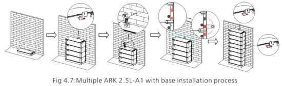
Step 1: Assemble the wall hangers together. If you want to install four packs, make four wall hangers together. We can parallel two to ten at a time . We recommend that the
stack number be no higher than six. However, if necessary our structure allows us to stack higher.
Step 2: Place the mount base where you want the PACK to be mounted. Put the wall hangers on the wall and match the base
Step 3:Mark the holes that need to be punched. We recommend two persons participate the installation.One person places the wall hangers on wall and ensure the gradienter
horizontal; the other person marks the holes. Noted that only two ends of the top wall hanger and the bottom wall hanger need to be marked.. After mark the holes, put down
the wall hangers.
Step 4: Drill a hole at the marked point with a depth of 55mm at the mark with a drill of φ8. Expand the bolt with a hammer into the hole in the wall , install the nut(including
elastic flat pad)and tighten the nut with a wrench.
Step 5: Hang the ARK2.5L-A1 on the wall hangers. Adjust the battery level with M6 external hexagon torque wrench and install the safety screws (M4x10 Combination screw) on both sides of all modules.
Step 6: Plug the connected power lines into PACK terminals (red positive terminal and black negative terminal). Plug the well-connected CAN communication line into the
communication ports of PCS and PACK.
Note:If more than 4 batteries are used, base mounting is recommended.
For floor installation, we recommend that the number of the stacked battery modules is no higher than six.
4.4 Electrical Connection
WARNING | Do not forget wear ESD wrist strap and gloves, safety gloves and goggles. |
Terminal Definition: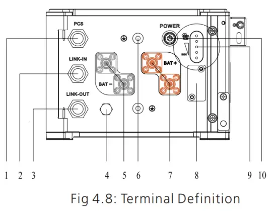
| Serial number | Item | Quantity | Specifications | Symbol |
| 1 | Communication Port | 1 | IP67 RJ45water p proof connector | PCS |
| 2 | Communication Port | 1 | proof IP67 RJ45water p connector | LINK-IN |
| 3 | Communication Port | 1 | IP67 RJ45water proof connector | LINK-OUT |
| 4 | Safety vent | 1 | Pressures inside released via the vent. | PCS |
| 5 | Negative terminal | 2 | IP67 –Black connector | BAT- |
| 6 | Grounding terminal | 2 | M6 Screw |  |
| 7 | Positive terminal | 2 | IP67–Red connector | BAT+ |
| 8 | USB interface | 1 | USB interface for Program Upgrade | BAT- |
| 9 | LED | 1 | Five leds | BAT+ |
| 10 | POWER button | 1 | IP67—Button to turn on or off the PACK | POWER |
Communication interface definition:
RS485&CAN crystal plug definition:
| Item | Crystal head picture | Serial no. | Definition |
| PC S | 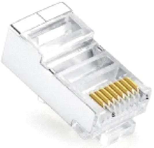 | 1 | RS485_B |
| 2 | RS 485_A | ||
| 3 | GND_COM | ||
| 4 | CANH | ||
| 5 | CANL | ||
| 6 | GND_COM | ||
| 7 | WAKE- | ||
| 8 | WAKE+ |
4.4.1 System connection diagram 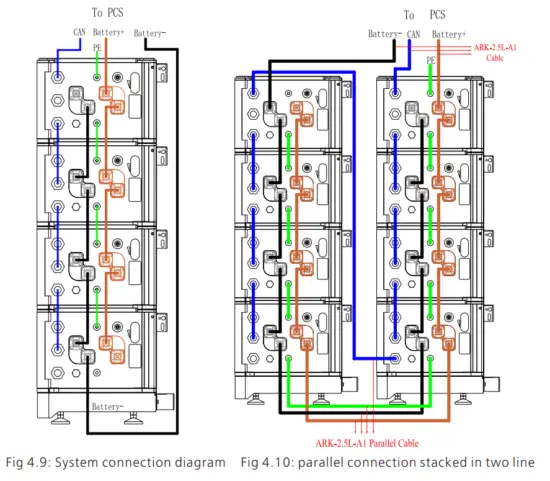
Note: The battery is not allowed to be installed in the running state, and all the RUN lights of battery modules should be off before installation.
To ensure system security, do not forget to install ground wire.
For the power lines connected to PCS, the positive power line is drawn from the top battery module, and the negative power line is drawn from the bottom battery module .
The breaker between PCS and ARK, we recommend to use molded case circuit breaker with rated working voltage greater than 500V and rated working current greater than
125A.
4.4.2 System connection diagram of two line
When stacked in two lines, you need to buy the accessory of wires connecting two stacks of battery systems. The connection mode is shown in the figure 13.
4.4.3 Electrical wiring connection
- When the power wiring harness is connected, please pay attention to the positive and negative terminals, the red terminals are connected to the positive terminals and the black terminals to the negative terminals.
- The PCS communication terminal is used to communicate to the PCS. Link-in terminals are used for signal inlet of multiple parallel battery packs. Link-out terminals are used for signal output of multiple parallel battery packs.
4.4.4 Power line connection
Press the position indicated in the figure above before disconnecting the power terminal.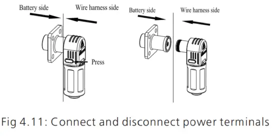
4.4.5 Communication line connection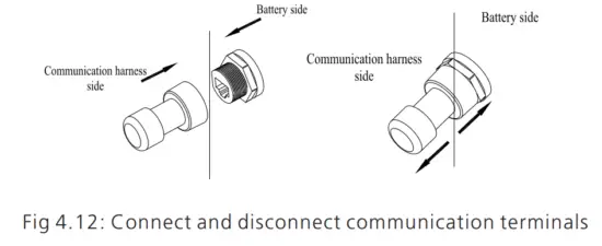
1.Parallel communication is the connection between the middle communication plug of the first module and the lower communication plug of the next module.
2.The uppermost communication plug of the top battery module is connected to the PCS.
Power on and off the Battery
WARNING | Ø The installation and use of batteries involve much-specialized knowledge. Therefore, technicians should be given appropriate technical training and obtain operational certificates in compliance with local laws and regulations. Please ensure technicians have obtained training certificate before operation. Ø Please stand on dry insulating objects and do not wear conductive material such as watches and necklace during operation. Insulated tools should be used. Ø Do not contact any positions with potential difference. Ø Prohibition sign should be hung on the battery: ” Non – professionals, do not touch. Ø If any abnormalities occur during the startup phase, power off the PACK immediately. After problem confirmed, proceed again. Ø Make sure the inverter is turned off before checking the PACK. |
5.1 Power On
| Power on the PACK by pressing power button(t>25) | ||
| Serial | Procedures | Acceptation criteria |
| 1 | Connect the battery and PCS | Make sure the wiring harnesses are well connected |
| 2 | Close the breaker of the PACK | Make sure the breaker is ON |
| 3 | Press POWER button for three to eight seconds. Observe the LED indication on panel. | 1.If both RUN/ALM and SOC lights turn on normally, PACK is powered on successfully. 2.If RUN/ALM light turns red, there is a failure and should solve it before power on again. |
| Power on the PACK by PCS | ||
| 1 | Connect the battery and PCS | Make sure the wiring harnesses are well connected |
| 2 | Close the breaker of the PACK | Make sure the breaker is ON |
| 3 | Power on the PCS. PCS outputs a wake up signal of 5V or an output main circuit voltage signal of 46-58V | 1.If both RUN/ALM and SOC lights turn on normal, PACK powers on successfully. 2.If RUN/ALM light turns red, there is a failure and should solve it before power on again. |
5.2 Power off
Press the power button to turn off the PACK and five LED lights will flicker for three times. If under the situation of multiple packs in parallel, only turning off one of the
packs then the whole battery system will turn off.
Maintenance Guide
6.1 Preparation
- Tools like safety gloves, crosshead driver and socket wrench should be prepared.
- Turn off and turn on the new PACK.
1. If the PACK is power-off. Press the power button for 3-8 seconds to turn on.
2. If the PACK is power-on. Press the power button once to turn off.
Before maintaining the battery, turn off the breaker and press the power button once to make sure the PACK is in the power-off mode. Follow the installation and wire connection procedures specified above. Ensure wires are properly connected before turn the breaker on. After that, turn on the breaker and press the power button of any PACK for 3-8 seconds to check if the system normally works.
6.2 PACK Replacement
- Wear safety gloves.
- Close the breaker and power off the PACK.
- Disconnect power lines and CAN communication lines of the PACK.
- Wall-mounting PACK: Uninstall the safety screws on both sides of the PACK. Lift up the PACK.
- Floor-standing PACK: Uninstall the safety part and open the connector at both ends of the battery of the batteries. Lift up the PACK.
- Put the PACK into the packing box according to the repair procedure and transport the PACK to the designated repair site.
- Install new PACK based on procedure specified in Section 4.
6.3 System Failure Information List and Troubleshooting Suggestions
| Error Indication | Error description | Error cause | Suggested actions |
| ALM | |||
| Discharge under voltage protection | Single-cell voltage below the threshold for under-voltage protection. | There is an over-discharge risk. User should stop discharging and arrange a recharge | |
| Charge over-voltage protection | Single-cell voltage exceeding the threshold for protection threshold. | 1. There is no safety threat; 2. User should stop charging. Idle PACK and it will turn to normal status. | |
| External CAN Communication failure | Communication loss between PCS and PACK. | 1. There is no safety threat and user should stop using the battery. 2. Check if PCS and battery communication terminal is well connected. 3.If PCS and PACK cannot communicate when the communication wire is confirmed well connected, user should contact the installer to repair the battery. |
| Interior CAN Communication failure | Communication loss between two parallel | 1. Check Can connection between two batteries, CAN connection between Linkin and Linkout; | |
| Parallel connection failure protection | Communication failure between two parallel-connected PACK | 1. Check Can connection between two batteries, CAN connection between Battery and PCS; | |
| (ALM Light on) | Discharge short circuit | External short circuit of PACK | There is safety risk and user should stop using battery User should contact installer to repair PCS and battery |
| Precharger short circuit | |||
| Precharger overtime circuit | |||
| Type inconsistency of PACK | The pack type is different | There is safety risk and user should stop using battery User should contact installer to use the same PACK in Parallel. | |
| Main circuit fault | BMS main power circuit failure | There is safety risk and user should stop using battery. User should contact installer to repair battery |
Technical Specifications
Functional parameters of ARK 2.5L-A1 Energy Storage System are as shown below:
| No. | Items | Specification |
| 1 | Battery Module | ARK 2.5L-A1 (2.56kWh, 51.2V, 27kg) |
| 2 | Nominal Capacity/Energy | 50Ah/2.56kWh |
| 3 | Rated/Usable Capacity/Energy | 45Ah/2.3 kWh |
| 4 | Typical Voltage | 51.2V |
| 5 | Operating Voltage | 47.2 – 56.8V |
| 6 | Standard charging current(25℃) | 25A |
| 7 | Battery Type | Cobalt Free Lithium Iron Phosphate (LFP) |
| 8 | Operative temperature range | -10~50℃ |
| 9 | Recommended operating temperature | 0℃~30℃ |
| 10 | Storage conditions | Temperature: -10°C ~ + 50°C Humidity:5%~95%RH Within six months after initial charge |
| 11 | Cooling | Natural cooling |
| 12 | Dimension (W/D/H) | 650/260/185mm |
| 13 | Weight | 27kg |
| 14 | Installation | Wall-mounted installation/floor standing installation |
| 15 | Ingress protection | IP65 |
| 16 | Cell safety certification | IEC62619/UL1642 |
| 17 | PACK safety certification | IEC62619/CE/RCM/ CEC |
| 18 | UN transportation test standard | UN38.3 |
| 19 | Communication port | CAN/RS485 |
| 20 | Parallel connection | Two-Ten PACKs |
| 21 | Maximum current for multiple parallel machines to PCS | 100A |
LED light definition | |||||||
| Status | Items | SOC indication | RUN/ALM | Remark | |||
| LED1 | LED2 | LED3 | LED4 | LED5 | |||
|
Charge SOC | 0%-25% | RUN/ALM light on and one SOC lights flicker | |||||
| 26%-50% | |||||||
| 51%-75% | |||||||
| 76%-99% | (t=1S) | ||||||
| 100% | |||||||
|
Discharge SOC | 100%-76% | ||||||
| 75%-51% | |||||||
| 50%-26% | |||||||
| 25%-5% | |||||||
| 5%-0% | RUN/ALM light flicker | ||||||
|
Idle | 100%-76% | ||||||
| 75%-51% | |||||||
| 50%-26% | |||||||
| 25%-5% | |||||||
| 5%-0% | RUN/ALM light flicker | ||||||
| Parallel connection | Parallel connection succeeds | RUN/ALM light flicker green | |||||
|
Protection | Cell charge overvoltage alarm |
LED1-LED4 indicates current remaining capacity |
| RUN/ALM light flicker green | |||
| Cell charge overvoltage protection |
| RUN/ALM light flicker green | |||||
| PACK charge overvoltage alarm | RUN/ALM light flicker green | ||||||
| PACK charge overvoltage protection | RUN/ALM light flicker green | ||||||
| Over charge and over discharge alarm | RUN/ALM light flicker green | ||||||
| Over charge and over discharge protection | RUN/ALM light flicker green | |||
| Charging current limit does not respond |
| RUN/ALM light flicker green | ||
| Charge and discharge high temperature alarm | RUN/ALM light flicker green | |||
| Charge and discharge high temperature protection | RUN/ALM light flicker green | |||
| Charge and discharge low temperature alarm | RUN/ALM light flicker green | |||
| Charge and discharge low temperature protection | RUN/ALM light flicker green | |||
| Cell discharge undervoltag e alarm | RUN/ALM light flicker green | |||
| Cell discharge undervoltag e protection | RUN/ALM light flicker green | |||
| PACK discharge undervoltag e alarm | RUN/ALM light flicker green | |||
| PACK discharge undervoltag e protection | RUN/ALM light flicker green | |||
| Charge and discharge Overcurrent hardware protection | RUN/ALM light flicker green |
| Mos high temperature alarm | RUN/ALM light flicker green | |||
| Mos high-temperature protection | RUN/ALM light flicker green | |||
| High-temperature environment alarm | RUN/ALM light flicker green | |||
| High-temperature environment protection | RUN/ALM light flicker green | |||
| Cell Large voltage difference alarm | RUN/ALM light flicker green | |||
| Cell Large voltage difference protection | RUN/ALM light flicker green | |||
| difference protection between PACK voltage and module voltage | RUN/ALM light flicker green | |||
| Parallel connection over charge and over discharge alarm | RUN/ALM light flicker green | |||
|
Fault,perso nnel handling required | Discharge short circuit |
LED1-LED4 indicates current remaining capacity | RUN/ALM light flicker red | |
| Precharged short circuit | RUN/ALM light flicker red | |||
| Precharged overtime circuit |
| RUN/ALM light flicker red | ||
| External CAN communicat ion failure |
| RUN/ALM light flicker red | ||
| Interior CAN communicat ion failure |
| RUN/ALM light flicker red | ||
| Parallel connection failure |
| RUN/ALM light flicker red |
| Type inconsistenc y of PACK |
| RUN/ALM light flicker red | ||
| Batteries failure protection | RUN/ALM light stays red | |||
| Voltage | ||||
| sampling | RUN/ALM light | |||
| anomaly protection | stays red | |||
| Current sampling fault | RUN/ALM light stays red | |||
| Main circuit | RUN/ALM light | |||
| fault | stays red |
IFpP/39.5/148/95/[16S]M/-10+50/90
Method for calculating rated capacity:
Rated capacity of the measured module: 45 Ah
Number of modules connected in parallel: 10
Calculated rated capacity (Ah) = 45 Ah×N = 45*N Ah (N=1~10)
Recommend charging method declared by the manufacturer:
- Constant current 25A charging to 54V;
- Constant current 10A charging to 55V;
- Constant current 2A charging to 55V;

 Download Manua
http://oss.growatt.com:80//common/downLoadSms/facb3359-39e8-4fc9-814a-fd05941c6764

Shenzhen Growatt New Energy CO.,LTD
No.28 Guangming Road, Shiyan Street, Bao’an District,
Shenzhen, P.R.China
No.28 Guangming Road, Shiyan Street, Bao’an District,
Shenzhen, P.R.China
T +86 755 2747 1942
E www.ginverter.com
W www.ginverter.com
[email protected]
+86 755 2747 1942
[email protected]
GR-UM-228-A-00


