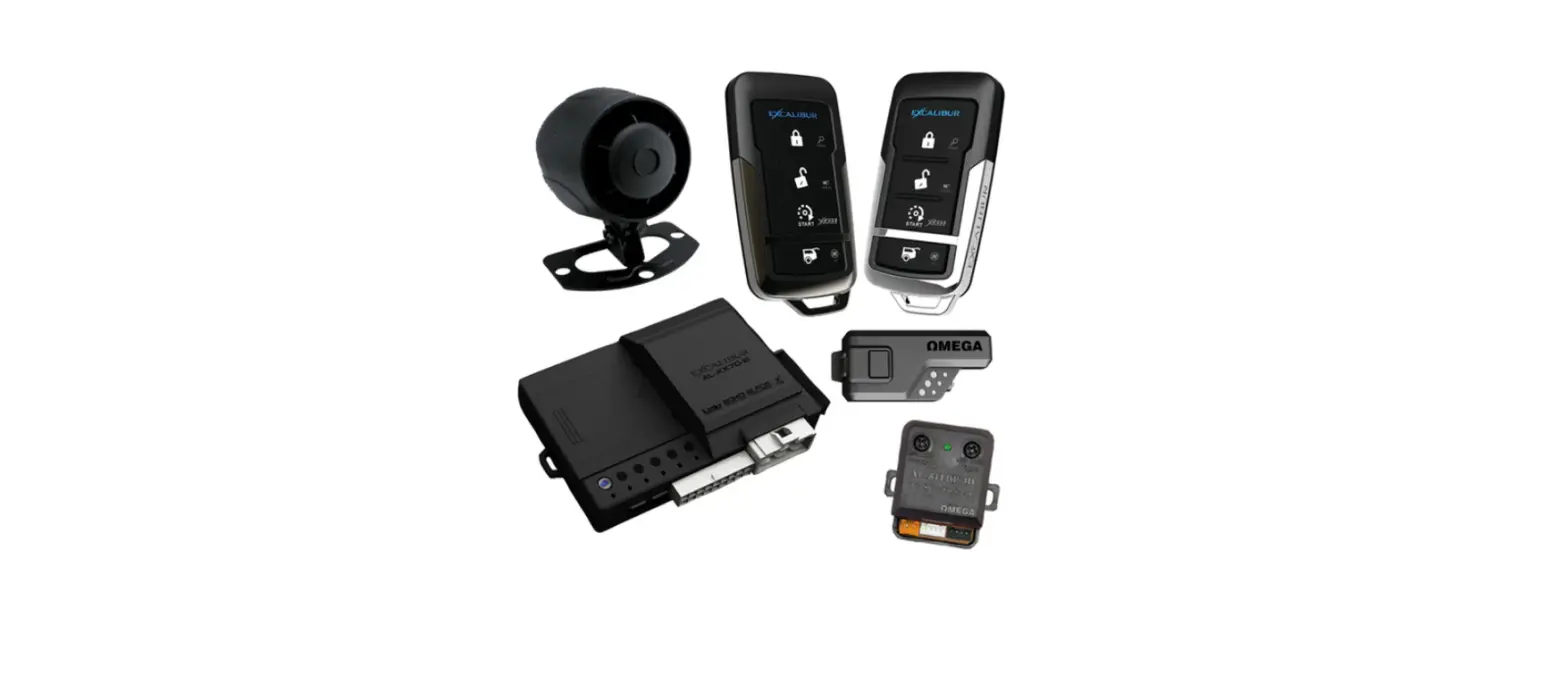
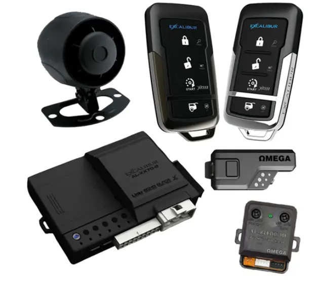
Car Alarm System AL-XX70 Excalibur Remote
Product Information
The AL-XX70 is a car alarm and remote start system that comes with various features such as a backup battery port, main input/output harness, door lock/unlock harness, temperature sensor, LED port, valet port, sensor ports, data ports, and antenna/status light/valet port. The system also supports PowerMaze technology for security-critical functions.
Backup Battery Port
The AL-XX70 comes with a backup battery port that uses a standard 9v battery (not included) with an included bracket and plug. It only supports security-critical functions.
Main Input/Output Harness
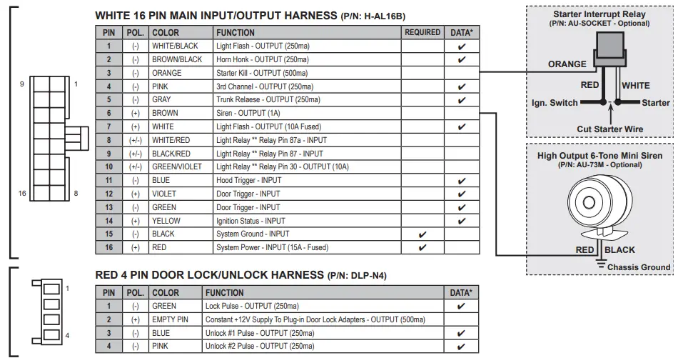
The main input/output harness is a white 16-pin harness with the following functions:
| PIN | POL. | COLOR | FUNCTION |
|---|---|---|---|
| 1 | – | WHITE/BLACK | Light Flash – OUTPUT (250ma) |
| 2 | – | BROWN/BLACK | Horn Honk – OUTPUT (250ma) |
| 3 | – | ORANGE | |
| 4 | – | PINK | Starter Kill – OUTPUT (500ma) 3rd Channel – OUTPUT (250ma) |
| 5 | – | GRAY | Trunk Relaese – OUTPUT (250ma) |
| 6 | + | BROWN | Siren – OUTPUT (1A) |
| 7 | + | WHITE | Light Flash – OUTPUT (10A Fused) |
| 8 | +/- | WHITE/RED | Light Relay ** Relay Pin 87a – INPUT |
| 9 | +/- | BLACK/RED | Light Relay ** Relay Pin 87 – INPUT |
| 10 | +/- | GREEN/VIOLET | Light Relay ** Relay Pin 30 – OUTPUT (10A) |
| 11 | – | BLUE | Hood Trigger – INPUT |
| 12 | + | VIOLET | Door Trigger – INPUT |
| 13 | – | GREEN | Door Trigger – INPUT |
| 14 | + | YELLOW | Ignition Status – INPUT |
| 15 | – | BLACK | System Ground – INPUT |
| 16 | + | RED | System Power – INPUT (15A – Fused) |
Door Lock/Unlock Harness
The door lock/unlock harness is a red 4-pin harness with the following functions:
| PIN | POL. | COLOR | FUNCTION |
|---|---|---|---|
| 1 | – | GREEN | Lock Pulse – OUTPUT (250ma) |
| 2 | + | EMPTY PIN | Constant +12V Supply To Plug-in Door Lock Adapters – OUTPUT (500ma) |
| 3 | – | BLUE | Unlock #1 Pulse – OUTPUT (250ma) |
| 4 | – | PINK | Unlock #2 Pulse – OUTPUT (250ma) |
Temperature Sensor
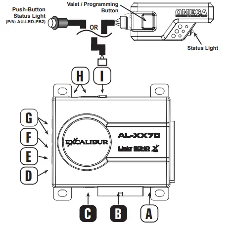
The temperature sensor is for high/low temp auto start and 2-way remote temp requests. It is located at the D point and should not be covered.
LED Port
The LED port is a white 2-pin port for optional remote mount status LED located at the E point.
Valet Port
The valet port is a blue 2-pin port for an optional hidden valet button located at the F point.
Sensor Ports
The white 4-pin plug-in sensor ports are located at the G point and come with a harness included with optional sensors.
Data Ports
The green and black data ports are located at the H point and are for the telematics/data sensor/vehicle interface module. DBI and iDatalink protocols are supported on both ports with installer feature #4.
Antenna/Status Light/Valet Port
The antenna/status light/valet port is located at the I point and supports any compatible plug-in antennas or pushbutton status light (P/N: AU-LED-PB2).
Product Usage Instructions
To use the AL-XX70 car alarm and remote start system, follow the instructions below:
- Connect the backup battery port to a standard 9v battery (not included) with the included bracket and plug. This port only supports security-critical functions.
- Connect the main input/output harness to the appropriate inputs and outputs in the car. Refer to the wiring diagram for the correct pin, polarity, color, and function.
- Connect the door lock/unlock harness to the appropriate door lock/unlock functions in the car. Refer to the wiring diagram for the correct pin, polarity, color, and function.
- If using the temperature sensor, make sure it is located at point D and is not covered.
- If using the LED port, connect the optional remote mount status LED to the white 2-pin port located at point E.
- If using the valet port, connect the optional hidden valet button to the blue 2-pin port located at point F.
- If using optional sensors, connect them to the white 4-pin plug-in sensor ports located at point G.
- If using a telematics/data sensor/vehicle interface module, connect it to the green and black data ports located at point H.
- Make sure the DBI and iDatalink protocols are supported on both ports with installer feature #4.
- If using a compatible plug-in antenna or pushbutton status light, connect it to the antenna/status light/valet port located at point I.
- Power on the system by connecting the system power input (15A – Fused) to a power source in the car.
- Follow the programming guide (for firmware v1.6) to program and configure the system for your specific needs.
Note: Optional accessories such as a starter interrupt relay (P/N: AU-SOCKET), push-button status light (P/N: AU-LED-PB2), and high output 6-tone mini siren (P/N: AU-73M) are available for purchase separately.
Programming Features Manually
- Turn the ignition key “ON”, then “OFF”.
- Press the valet button equal to the desired bank (press 5x for Bank 5, etc.)
- This must be done within 5 seconds of step 1.
- The siren/horn will chirp & the status light will flash indicating the selected bank (see bank header).
- NOTE: You cannot move from bank to bank. You must start over to change banks.
- NOTE: When accessing BANK 10 (Installer), you will hear a long chirp after 5 presses (User features). Continue presses 6-10 without delay. You will hear a 2nd long chirp after 10 presses.
- Press the valet button equal to the desired feature’s number.

- The siren/horn will chirp equal to the selected feature.
- Finish presses before hearing any chirps. EXAMPLE: press the valet 5x, then you’ll hear 5 chirps.
- Press the transmitter button to select the desired setting.
- 1-BUTTON MODELS: Change the feature by pressing the transmitter button equal to the desired setting. Complete all presses before hearing any chirps.
- The siren/horn will chirp equal to the selected setting.
- Repeat steps 3 & 4 at this time IF you wish to change additional features.
- Turn the ignition key “ON” and then “OFF” to exit programming.
- NOTE: The system will exit automatically at any time after 10 seconds of no activity.

Programming Transmitters
Standard Programming: Use this method to program additional or replacement transmitters.
BEFORE YOU BEGIN: Have all transmitters which are to operate the system at hand.
- Turn the ignition key “ON” (do not start).
- Press the valet button 5 times within 5 seconds of step 1.

- The horn will briefly sound
- Press & release the “lock” button on each transmitter one after the other.
- 1-button models press the “start” button.
- The siren/horn will chirp once for each transmitter.
- NOTE: When the first new transmitter is learned all previous transmitters are erased.
- NOTE: All other button functions will automatically be assigned.
- Turn the ignition key “OFF”.
- NOTE: The system will exit automatically at any time after 10 seconds of no activity.

Alarm Diagnostics
Alarm Quick Test Mode: Use this mode to test all zones of the alarm system and quickly adjust any sensors.
- Press & hold the valet button.

- Press the Lock button on the remote within 2 seconds of step 1 (before the system enters valet mode).
- The LED will begin to flash rapidly.
- Release the valet button.
- The siren/horn will chirp indicating all alarm zone violations. See the table below.
- NOTE: Chirps will repeat every 2 seconds while the trigger remains violated.
- NOTE: If multiple zones are triggered the chirps will cycle thru the zones every 2 seconds then repeat.
- Press Lock or Unlock on the controller or power cycle the system to exit.
- NOTE: There is no exit timer to this feature, chirps will continue until the zone is clear or the mode is exited.

Zone Violation Recall: To diagnose alarm triggers, disarm/unlock the alarm with the remote and the status LED will flash to indicate which zone(s) were triggered last. Turn the ignition key “ON” to clear the alarm trigger memory.
| LED Flashes/Chirps | Alarm Quick Test | Zone Violation Recall |
| 1 | Sensor Full Trigger | – |
| 2 | Hood | Hood |
| 3 | Door | Door |
| 4 | Sensor Warning | Sensor Port Trigger |

Features Banks
| BANK 5 – User Features: Ignition on, off, press valet 5 times (Long chirp/fast LED flash) | |||||||
| # Feature | Lock Button | Unlock Button | Trunk Button | Start Button | Lock + Unlock | Trunk+Start | |
| CONVENIENCE | 1 External Remote Start Run Time | 3 min | 10 min | 15 min | 20 min | 30 min | 35 min |
| 2 Flashing Light Upon Disarm | 30 Seconds | Off (Flash) | |||||
| 3 Confirmation Chirp Volume | Low | Med-Low | Med-High | High | |||
| 4 BROWN wire / HORN pulse | BROWN: Steady Pulse MED | BROWN: Pulse LO | BROWN: Pulse MED | BROWN: Pulse HIGH | BROWN: Steady HORN: Human Panic! | ||
| 5 Lock w/ Ignition On | On | Off | |||||
| 6 Unlock w/ Ignition Off | Off | Unlock #1 | Unlock #2 | Unlock #1 & #2 | |||
| 7 Door Open Bypass for Feat. #5 | On | Off | |||||
| 8 Unlock w/ Trunk Release | On | Off | |||||
| SECURITY | 9 Last Door Arming | Off | On w/o Lock | On w/ Lock | |||
| 10 Automatic Rearming | Off | On w/o Lock | On w/ Lock | Enhanced | |||
| 11 Confirmation Chirps | Siren + Horn | Siren Only | Horn Only | On Demand | Off | ||
| 12 Ignition Anti-Carjacking | On | Off | |||||
| 13 Door Anti-Carjacking | On | Off | |||||
| 14 Remote Anti-Carjacking | On | Off | |||||
| 15 Override Code | See operation guide for programming instructions. DEFAULT: 1,0 | ||||||
| 16 Ignition Override | On | Off | |||||
| 17 Alarm Trigger Duration | 30 sec | 60 sec | 90 sec | 120 sec | |||
| 18 Arming Delay | 3 sec | 15 sec | 30 sec | 45 sec | |||
| 19 Open Door Warning Upon Arming | On | Off | |||||
| 20 RFID Anti-Carjacking (410-07 TX) | On | Off | |||||
| BANK 10 – Installer Features: Ignition on, off, press valet 10 times (2nd Long chirp/fast LED flash) | |||||||||
| # | Feature | Lock Button | Unlock button | Trunk button | Start button | Lock + Unlock | Trunk + Start | ||
| 1 PINK Wire / Data RS Activation | 0.8sec Pulse & Data Start: 1 Press | 0.8sec Pulse & Data Start: 2 Press | 0.8sec Pulse & Data Start: 3 Press | 0.8sec Pulse & Data Start: 4 Press | 0.8 sec Defrost Pulse / Data Start 2 Press | 10 min Defrost Pulse / Data Start 2 Press | |||
| 2 Light Relay Function | Dome Light | Light Flash | Trunk | Horn | CH5 Pulse | CH5 Latch | |||
| 3 Door Lock/Unlock Outputs | 0.8 sec | 3 sec | Double Unlock | Total Closure | |||||
| 4 Data Port Protocol | Green: DBI Black: DBI | Green: iData Black: iData | Green: DBI Black: iData | Green: iData Black: DBI | |||||
| 5 Alarm Functions | On | Off | Off-Unlock Only | ||||||
| 6 WHITE/BLACK | BROWN/BLACK Wire Functions | Light Flash | Horn | Light Flash | CH5 Pulse | CH4 Pulse | Horn | CH4 Pulse | CH5 Pulse | CH4 Latch | CH5 Pulse | CH4 Pulse | CH5 Latch | |||
| 7 Lock On Prewarn | On | Off | |||||||
| 8 Starter Interrupt | Alarm Only | Off | Automatic | ||||||
| 9 Low Current Mode | On | Off | |||||||
| FEATURE SETTING KEY: | Default Setting | ||||||||
TIP: You can program features via your computer at www.OmegaWeblink.com
Features Reset

- Enter Bank 10 feature programming (Installer features – DO NOT SELECT ANY FEATURES).
- Press LOCK + UNLOCK
- 1-button/2-button models: Press the START button 5 times
- You will hear a long siren chirp to indicate reset & exit programming.
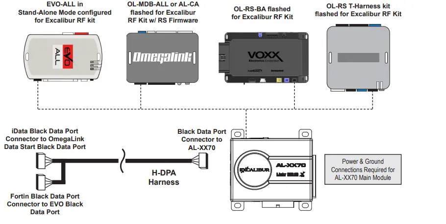
Using AL-XX70 and Data Start/RS Firmware
The AL-XX70 can be installed as an alarm upgrade for OmegaLink data start units (flashed for “Excalibur RF kit”). Use the chart below to see compatible models, and which protocols to use. You can use either data port on the AL-XX70 to free up the other for additional accessories.
BACKUP BATTERY PORT – Uses standard 9v battery (not included) with included bracket & plug.
Featuring PowerMaze technology – It only supports security-critical functions! The function is supported via the data ports. Confirm vehicle support in the interface module install guide. The Light Relay function is programmable, see installer feature #2 for other options.
- TEMPERATURE SENSOR – DO NOT COVER (For high/low temp auto start and 2-way remote temp request)
- WHITE 2 PIN LED PORT – For optional remote mount status LED
- BLUE 2 PIN VALET PORT – For optional hidden valet button
- WHITE 4 PIN PLUG-IN SENSOR PORTS (harness included w/ optional sensors)
- H GREEN & BLACK DATA PORTS – For Telematics / Data Sensor / Vehicle Interface Module. (DBI & iDatalink protocols supported on both ports – installer feature #4)
- I ANTENNA / STATUS LIGHT / VALET PORT – Supports any compatible plug-in antennas or push

Using AL-XX70 and Data Start/RS Firmware
Tech Support
Phone: 800-921-TECH (8324) | Web: OmegaDealer.com | FB dealer group: Facebook.com/groups/omegadealer |
Corporate Site & Product Info: CarAlarm.com


