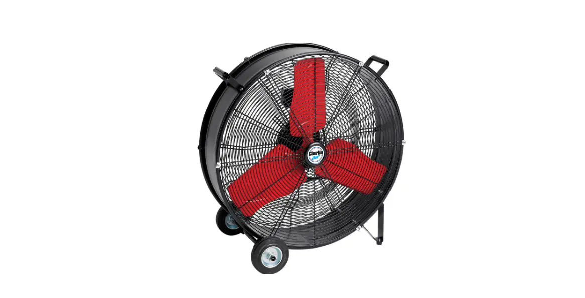
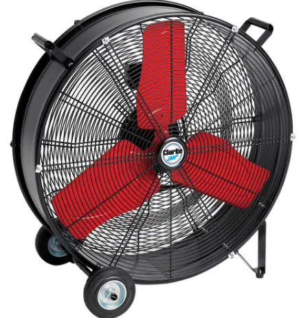
Clarke CAM24110V 24-Inch Drum Fan 
INTRODUCTION
Thank you for purchasing this CLARKE 24” Drum Fan.Before attempting to use this product, please read this manual thoroughly and follow the instructions carefully. In doing so you will ensure the safety of yourself and that of others around you, and you can look forward to your purchase giving you long and satisfactory service.
SPECIFICATIONS
| MODEL | CAM24110V |
| Part No: | 3231564 |
| Voltage: | 110 V~ (50Hz) |
| Ingress Protection Rating | IP20 |
| Insulation Class | 1 |
| Fan Power Input | 115.8 W |
| Duty Cycle | S1 (continuous) |
| Fan Speeds | |
| Position 1 | 879 rpm |
| Position 2 | 931 rpm |
| Standby Power Consumption | N/A |
| Fan Sound Power Level | 77 dB(A) |
| Sound Power Measured | 81.3 dB(A) LWa |
| Guaranteed Sound Level | 83.8 dB Lwa |
| Maximum Fan Flow Rate | 284 m3/m |
| Maximum Air Velocity | 2.3 m/sec |
| Service Value | 2.5 m3#mmm_W |
| Measurement Standard for Service Value | EU 206/2012 |
| Dimensions (D x W x H) mm | 675 x 275 x 688 |
| Weight: | 16.1 kg |
ELECTRICAL CONNECTIONS
WARNING
READ THESE ELECTRICAL SAFETY INSTRUCTIONS THOROUGHLY BEFORE CONNECTING THE PRODUCT TO THE POWER SUPPLY.
Before switching the product on, make sure that the voltage of your electricity supply is the same as that indicated on the rating plate. Connecting it to any other power source may cause damage.If the plug has to be changed due to damage, a replacement should be fitted, following the wiring instructions shown below. The old plug must be disposed of as insertion into a 110v socket could cause an electrical hazard.
WARNING:
THE WIRES IN THE POWER CABLE OF THIS PRODUCT ARE COLOURED IN ACCORDANCE WITH THE FOLLOWING CODE: BLUE = NEUTRAL BROWN = LIVE YELLOW =
If the colours of the wires in the power cable of this product do not correspond with the markings on the terminals of your plug, proceed as follows.
- The Blue wire must be connected to the terminal which is marked N or Neutral.
- The Brown wire must be connected to the terminal which is marked L or Live.
- The Yellow wire must be connected to the terminal which is marked E or Earth.If in any doubt, consult a qualified electrician. DO NOT attempt any repairs yourself.
SAFETY PRECAUTIONS
- ALWAYS read the manual before use.
- Suitable for indoor use only.
- Avoid using in dusty environments.
- DO NOT use in environments containing chemical fumes etc.
- DO NOT use as an extractor fan.
- DO NOT use in areas of high humidity/water vapour, i.e. bathrooms etc.
- DO NOT connect the fan to duct system.
- DO NOT cover the fan with clothing or any material that will restrict free airflow through the fan.
- NEVER touch the blades with your hand or any loose object.
- ALWAYS unplug the fan before moving it or performing maintenance.
- DO NOT touch the fan when your hands are wet.
- ALWAYS unplug the fan when it is not in use.
- NEVER unplug the fan by holding the cable. Unplug by holding the plug.
- NEVER use the fan if the cable or plug are damaged.
- NEVER use the fan close to fires.
- DO NOT use this fan with any solid-state speed control device to reduce the risk of fire or electric shock.
- Those who are not qualified electricians should not disassemble or repair this product.
ENVIRONMENTAL RECYCLING POLICY
Through the purchase of this product, the customer is taking on the obligation to deal with the WEEE in accordance with the WEEE regulations in relation to the treatment, recycling & recovery and environmentally sound disposal of the WEEE.In effect, this means that this product must not be disposed of with general household waste. It must be disposed of according to the laws governing Waste Electrical and Electronic Equipment (WEEE) at a recognised disposal facility.
OPERATION
Turn the switch on the speed regulator to select the fan speed required.
| CAM24110v | |
| Position 1 | 879 RPM |
| Position 2 | 931 RPM |
MAINTENANCE
WARNING:
NEVER OPERATE THE FAN WITH THE FRONT OR REAR GUARDS REMOVED.
Have any repairs carried out by a suitably qualified person.
- The motor bearings are permanently sealed for life and do not require any additional lubrication.

- Disconnect the power cable from the power supply.
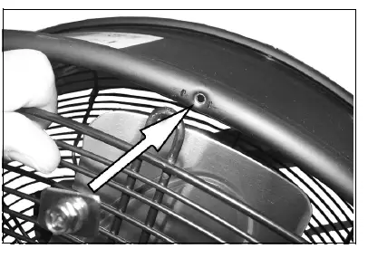
- Unscrew the front guard and lift it away carefully.
- Wipe the fan blades with dry cloth and remove any dust from the motor assembly with a soft paintbrush, vacuum cleaner or jet of compressed air.
- Always wear suitable eye protection when using compressed air.
- Never use polish or any corrosive liquid that will damage the surface finish.
- Replace the guard securely before use.
PARTS LIST AND DIAGRAM

| NO | DESCRIPTION |
| 1 | Front Grill |
| 2 | Blade Assembly |
| 3 | Handle |
| 4. | Drum Body |
| 5 | Capacitor |
| 6 | Switch |
| 7 | Switch Box |
| NO | DESCRIPTION |
| 8 | Switch Knob |
| 9 | Fan Motor |
| 10 | Rear Grill |
| 11 | Power Cable |
| 12 | Wheel & Stub Axle |
| 13 | Feet |
| 14 | Axle Support |
GUARANTEE
This product is guaranteed against faulty manufacture for a period of 12 months from the date of purchase. Please keep your receipt which will be required as proof of purchase.This guarantee is invalid if the product is found to have been abused or tampered with in any way, or not used for its intended purpose.Faulty goods should be returned to their place of purchase, no product can be returned to us without prior permission. This guarantee does not effect your statutory rights.