Zennio ZVITXLX4 PC-ABS Capacitive Push Button User Manual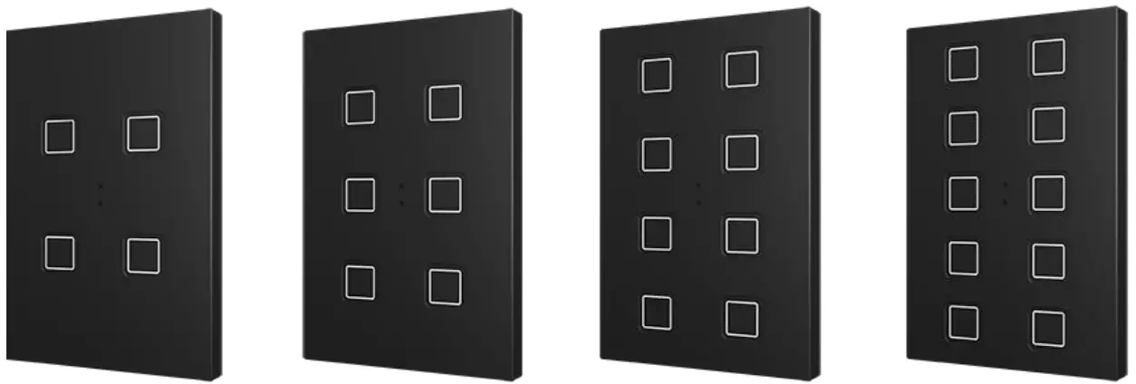
INTRODUCTION
TECLA XL
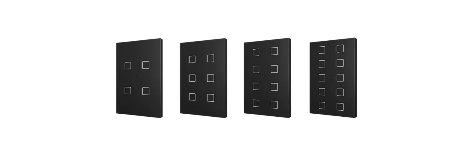
Tecla XL is a KNX multifunction capacitive touch switch from Zennio with proximity sensor, luminosity sensor and backlighted buttons.
They are offered at a reduced weight, with four, six, eight or ten capacitive touch buttons (according to the user’s needs) with LED backlight to confirm the press of the buttons as well as showing states.
Tecla XL is a fully customisable solution for the control of rooms where user control of air conditioning systems, lighting, blinds, scenes, etc. is required.
The versatility offered by the functionality of buttons is complemented by an internal temperature sensor and a thermostat function, as well as an elegant design with fully customisable backlit icons.
The most outstanding features of Tecla XL are:
- Fully customisable backlit icons.
- 4 / 6 / 8 / 10 touch buttons, which can operate as individual or pair controls:
- Horizontally or vertically-oriented configuration.
- Light indicator (LED) for every button.
- Buzzer for an audible acknowledgement of user actions (with the possibility of disabling it either by parameter or by object).
- Possibility of locking / unlocking the touch panel through binary orders or scenes.
- Welcome Back object (binary or scene) which is sent to the KNX bus when a pulsation is detected after a certain period (configurable) of inactivity.
- Built-in temperature sensor.
- Ambient luminosity sensor for brightness automatic adjustment.
- Proximity sensor for quick start.
- Thermostat function.
- Heartbeat or periodical “still-alive” notification.
INSTALLATION
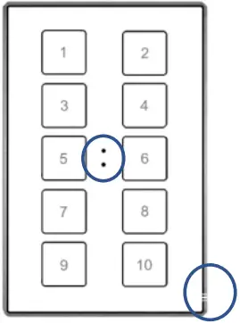
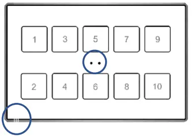
Figure 1 shows the connection outline of Tecla XL:
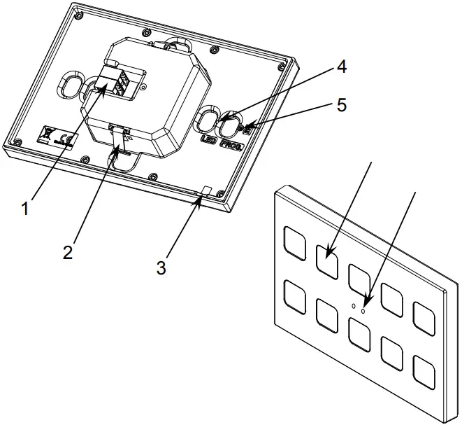
- KNX connector
- Fixing clips.
- Temperature probe.
- Programming LED.
- Programming Button.
- Touch area.
- Proximity and Luminosity.
Tecla XL is connected to the KNX bus through the built-in terminal (1). An external DC power supply is not needed.
A short press on the programming button (5) will make the device enter the programming mode. The programming LED (4) will then light in red. On the contrary, if this button is held while the device gets connected to the bus, the device will enter the safe mode. In such case, the programming LED will blink in red colour.
For detailed information about the technical features of Tecla XL, as well as on security and installation procedures, please refer to the device Datasheet, bundled within the device packaging and also available at www.zennio.com.
START-UP AND POWER LOSS
After download or device reset it is necessary to wait for about 2 minutes without performing any action in order to make it possible a proper calibration of:
- Proximity sensor.
- Luminosity sensor.
- Button presses.
For a correct calibration of the proximity and brightness sensors it is recommended not to remain too close or place anything less than 50cm approximately and do not hit with direct light to the device during this time.
CONFIGURATION
After importing the corresponding database in ETS and adding the device into the topology of the project, the configuration process begins by entering the Parameters tab of the device.
GENERAL
In order to allow the device to perform the desired functions, a number of options must be parameterized, either related to its general behaviour or to advanced features.
CONFIGURATION
In the “Configuration” tab, the general settings are displayed.
ETS PARAMETERISATION
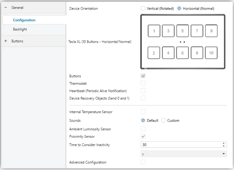
The following parameters are shown:
Device Orientation [Vertical (Rotated) / Horizontal (Rotated)] 1 : enables horizontal or vertical orientation to be assigned to the device, for easy identification of the push-buttons during configuration process (ETS will show a figure with the final distribution of the push-buttons). To prevent inconsistency in the configuration, please note the following criterium
Vertical (rotado):
Temperature probe hole on the right side and the sensors on the middle.
Horizontal (normal):
Temperature probe hole on the left of the bottom side and sensors on the middle.
- Buttons [enabled]: read-only parameter to make it evident that the “Buttons” tab is always enabled in the tab tree on the left. See section 2.2 for details.
- Thermostat [disabled/enabled]: enables or disables the “Thermostat” tab in the tree on the left. See section 2.3 for details.
- Heartbeat (Periodic Alive Notification) [disabled/enabled]: incorporates a one-bit object to the project (“[Heartbeat] Object to Send ‘1’”) that will be sent periodically with value “1” to notify that the device is still working (still alive).

Note: the first sending after download or bus failure takes place with a delay of up to 255 seconds, to prevent bus overload. The following sendings march the period set.

1 The default values of each parameter will be highlighted in blue in this document, as follows: [default/rest of options].
- Device Recovery Objects (Send 0 and 1) [disabled/enabled]: this parameter lets the integrator activate two new communication objects (“[Heartbeat] Device Recovery”), which will be sent to the KNX bus with values “0” and “1” whenever the device begins operation (for example, after a bus power failure). It is possible to parameterise a certain delay [0…255][s] to this sending.

Note: After download or bus failure, the sending takes place with a delay of up to 6,35 seconds plus the parameterised delay, to prevent bus overload.
- Internal Temperature Sensor [disabled/enabled]: enables or disables the “Temperature Sensor” tab in the tree on the left. See section 2.1.2 for details.
Sounds [Default / Custom]: sets whether the sound functions (button beeps, alarm and doorbell) should work according to the pre-defined configuration or to a user-defined configuration. See section 2.1.4 for details. - Ambient luminosity sensor [disabled/enabled]: enables setting the ambient luminosity sensor. When the sensor is enabled, a new tab for its configuration is shown. See section 2.1.5 for details.
- Proximity Sensor [disabled/enabled]: enables the proximity sensor. This functionality permits “waking up” the device when detecting presence, see section 2.1.6.
- Time to Consider Inactivity [1…30…255][s/min/h]: allows setting a time after which, if no pulsation or proximity detection has occurred, the LEDs turn off (or acquire the brightness level configured, see section 2.1.3).
- Advanced Configuration [disabled/enabled]: enables or disables the “Advanced” tab in the tree on the left. See section 2.1.7 for details.

TEMPERATURE SENSOR
The internal temperature probe can monitor the ambient temperature of the room, thus making the device capable of reporting it to the KNX bus and of triggering certain actions when the temperature reaches specific values.
Please refer to the specific manual “Temperature Probe” (available in the product section at the Zennio homepage, www.zennio.com) for detailed information about the functionality and the configuration of the related parameters.
BACKLIGHT
Capacitive touch switches are able to manage the brightness of the LED according to two operating modes: normal mode and night mode.
Please refer to the specific manual “Brightness” (available in the product section at the Zennio website, www.zennio.com) for detailed information about the functionality and the configuration of the related parameters
SOUNDS
For detailed information about the functionality and the configuration of the related parameters, please refer to the specific manual “Capacitive Touch Switches” available in the Tecla XL product section at the Zennio homepage, www.zennio.com.
AMBIENT LUMINOSITY SENSOR
Capacitive touch switches incorporate a luminosity sensor to receive and monitor ambient brightness measurement.
Please refer to the specific manual “Luminosity and Proximity Sensor” (available in the product section at the Zennio homepage, www.zennio.com) for detailed information about the functionality and the configuration of the related parameters.
PROXIMITY SENSOR
Please refer to the specific manual “Proximity and Luminosity Sensor” (available in the product section at the Zennio homepage, www.zennio.com) for detailed information about the functionality and the configuration of the related parameters.
ADVANCED CONFIGURATION
For detailed information about the functionality and the configuration of the related parameters, please refer to the specific manual “Capacitive Touch Switches” available in the Tecla XL product section at the Zennio homepage, www.zennio.com.
For detailed information about the functionality and the configuration of the related parameters, please refer to the specific manual “Capacitive Touch Switches” available in the Tecla XL product section at the Zennio homepage, www.zennio.com
THERMOSTAT
Capacitive touch switches implement one Zennio thermostat which can be enabled and fully customised.
Please refer to the specific manual “Zennio Thermostat” (available in the product section at the Zennio website, www.zennio.com) for detailed information about the functionality and the configuration of the related parameters.
ANNEX I. COMMUNICATION OBJECTS
- “Functional range” shows the values that, with independence of any other values permitted by the bus according to the object size, may be of any use or have a particular meaning because of the specifications or restrictions from both the KNX standard or the application program itself.
Note:
- The objects shown in this table are from model Tecla XL X10. Please note that certain objects will not be available in models with less push buttons.
Number Size I/O Flags Data type (DPT) Functional Range Name Function
| Number | Size | I/O | Flags | Data type (DPT) | Functional Range | Name | Function |
| 1 | 1 Bit | C – – T – | DPT_Trigger | 0/1 | [Heartbeat] Object to Send ‘1’ | Sending of ‘1’ Periodically | |
| 2 | 1 Bit | C – – T – | DPT_Trigger | 0/1 | [Heartbeat] Device Recovery | Send 0 | |
| 3 | 1 Bit | C – – T – | DPT_Trigger | 0/1 | [Heartbeat] Device Recovery | Send 1 | |
| 4 | 1 Byte | I | C – W – – | DPT_SceneNumber | 0 – 63 | [General] Scene: Receive | 0 – 63 (Run Scene 1-64) |
| 5 | 1 Byte | C – – T – | DPT_SceneControl | 0-63; 128-191 | [General] Scene: Send | 0 – 63/128 – 191 (Run/Save Scene 1-64) | |
| 6 | 1 Bit | I | C – W – – | DPT_Enable | 0/1 | [General] Touch Locking | 0 = Unlock; 1 = Lock |
| 1 Bit | I | C – W – – | DPT_Enable | 0/1 | [General] Touch Locking | 0 = Lock; 1 = Unlock | |
| 7 | 1 Bit | C – – T – | DPT_Switch | 0/1 | [General] Welcome Back Object | Switch Object Sent on Wake Up | |
| 8 | 1 Bit | I | C – W – – | DPT_Enable | 0/1 | [General] Sounds – Disabling Button Sound | 0 = Disable Sound; 1 = Enable Sound |
| 1 Bit | I | C – W – – | DPT_Enable | 0/1 | [General] Sounds – Disabling Button Sound | 0 = Enable Sound; 1 = Disable Sound | |
| 9 | 1 Bit | I | C – W – – | DPT_Ack | 0/1 | [General] Sounds – Doorbell | 1 = Play a Doorbell Sound; 0 = Nothing |
| 1 Bit | I | C – W – – | DPT_Ack | 0/1 | [General] Sounds – Doorbell | 0 = Play a Doorbell Sound; 1 = Nothing | |
| 10 | 1 Bit | I | C – W – – | DPT_Alarm | 0/1 | [General] Sounds – Alarm | 1 = Play Alarm Intermittent Sounds; 0 = Stop Alarm Sounds |
| 1 Bit | I | C – W – – | DPT_Alarm | 0/1 | [General] Sounds – Alarm | 0 = Play Alarm Intermittent Sounds; 1 = Stop Alarm Sounds | |
| 11, 12, 13, 14, 15 | 1 Bit | I | C – W – – | DPT_Switch | 0/1 | [General] Welcome Back Object – Additional Condition | Additional Condition Object x |
| 16 | 1 Bit | I | C – W – – | DPT_Enable | 0/1 | [General] Proximity Sensor | 0 = Disable; 1 = Enable |
| 17 | 1 Bit | I | C – W – – | DPT_Start | 0/1 | [General] External Proximity Detection | 1 = Detection |
| 18 | 1 Bit | C – – T – | DPT_Start | 0/1 | [General] Proximity Detection | Send 1 when Proximity is Detected | |
| 19 | 1 Bit | C – – T – | DPT_Bool | 0/1 | [General] Luminosity (1-Bit) | 0 = Over Threshold; 1 = Under Threshold | |
| 1 Bit | C – – T – | DPT_Bool | 0/1 | [General] Luminosity (1-Bit) | 0 = Under Threshold; 1 = Over Threshold | ||
| 20 | 1 Byte | O | C R – – – | DPT_Scaling | 0% – 100% | [General] Luminosity (Percentage) | 0% … 100% |
| 21 | 2 Bytes | O | C R – – – | DPT_Value_Lux | [General] Luminosity (Lux) | 0 Lux … 670760 Lux | |
| 22 | 1 Bit | I | C – W – – | DPT_DayNight | 0/1 | [General] Backlight Mode | 0 = Night Mode; 1 = Normal Mode |
| 1 Bit | I | C – W – – | DPT_DayNight | 0/1 | [General] Backlight Mode | 0 = Normal Mode; 1 = Night Mode | |
| 23 | 1 Byte | I | C – W – – | DPT_Scaling | 0% – 100% | [General] Display – Brightness | 0% … 100% |
| 24 | 1 Byte | I | C – W – – | DPT_Scaling | 0% – 100% | [General] Display – Contrast | 0% … 100% |
| 25, 31, 37, 43, 49, 55, 61, 67, 73, 79 | 1 Bit | I | C – W T – | DPT_Switch | 0/1 | [Btn][Ix] Switch | Send Selected Value on Short Press |
| 1 Bit | I | C – W T – | DPT_Switch | 0/1 | [Btn][Ix] Hold & Release | Send Selected Values on Hold and Release Presses | |
| 1 Bit | I | C – W T – | DPT_Switch | 0/1 | [Btn][Ix] Two Objects – Short Press | Send Selected Value on Short Press | |
| 1 Bit | C – – T – | DPT_Switch | 0/1 | [Btn][Ix] Light – On/Off | (Short Press) Switch Between On and Off | ||
| 1 Bit | C – – T – | DPT_Step | 0/1 | [Btn][Ix] Shutter – Stop/Step | (Short Press) 0 = Stop Shutter/Step Up; 1 = Stop Shutter/Step Down | ||
| 1 Bit | C – – T – | DPT_Trigger | 0/1 | [Btn][Ix] Shutter – Stop | (End Pressing) Stop Shutter | ||
| 25, 31, 37, 43, 49 | 1 Bit | C – – T – | DPT_Switch | 0/1 | [Btn][Ix] Light – On | (Short Press) Send On | |
| 1 Bit | C – – T – | DPT_Switch | 0/1 | [Btn][Ix] Light – Off | (Short Press) Send Off | ||
| 25, 31, 37, 43, 49, 55, 61, 67, 73, 79 | 1 Bit | C – – T – | DPT_Step | 0/1 | [Btn][Ix] Shutter – Stop/Step | (Short Press) Stop Shutter/Step Up | |
| 1 Bit | C – – T – | DPT_Step | 0/1 | [Btn][Ix] Shutter – Stop/Step | (Short Press) Stop Shutter/Step Down | ||
| 26, 32, 38, 44, 50, 56, 62, 68, 74, 80 | 4 Bit | I | C – W T – | DPT_Control_Dimming | 0x0 (Stop) 0x1 (Dec. by 100%) … 0x7 (Dec. by 1%) 0x8 (Stop) 0xD (Inc. by 100%) … 0xF (Inc. by 1%) | [Btn][Ix] Light – Dimming | Long Press) Switch Between Dimming Up and Down |
| 27, 33, 39, 45, 51, 57, 63, 69, 75, 81 | 1 Bit | C – – T – | DPT_UpDown | 0/1 | [Btn][Ix] Shutter – Move | (Long Press) 0 = Up ; 1 = Down | |
| 1 Bit | C – – T – | DPT_UpDown | 0/1 | [Btn][Ix] Shutter – Move | (Start Pressing) Switch Between Up and Down | ||
| 1 Bit | I | C – W T – | DPT_Switch | 0/1 | [Btn][Ix] Two Objects – Long Press | Send Selected Value on Long Press | |
| 1 Bit | C – – T – | DPT_UpDown | 0/1 | [Btn][Ix] Shutter – Move | (Long Press) Up | ||
| 1 Bit | C – – T – | DPT_UpDown | 0/1 | [Btn][Ix] Shutter – Move | (Long Press) Down | ||
| 1 Bit | C – – T – | DPT_UpDown | 0/1 | [Btn][Ix] Shutter – Move | (Start Pressing) Up | ||
| 1 Bit | C – – T – | DPT_UpDown | 0/1 | [Btn][Ix] Shutter – Move | (Start Pressing) Down | ||
| 28, 34, 40, 46, 52, 58, 64, 70, 76, 82 | 1 Bit | I | C – W T – | DPT_Switch | 0/1 | [Btn][Ix] LED On/Off | 0 = Off; 1 = On |
| 1 Bit | I | C – W T – | DPT_Switch | 0/1 | [Btn][Ix] LED On/Off | 0 = On; 1 = Off | |
| 29, 35, 41, 47, 53, 59, 65, 71, 77, 83 | 1 Byte | I | C – W T – | DPT_Scaling | 0% – 100% | [Btn][Ix] Scaling | Send Selected Percentage Value on Short Press |
| 1 Byte | I | C – W T – | DPT_Value_1_Ucount | 0 – 255 | [Btn][Ix] Counter – 1-Byte Unsigned | Send Selected Value on Short Press | |
| 1 Byte | I | C – W T – | DPT_Value_1_Count | -128 – 127 | [Btn][Ix] Counter – 1-Byte Signed | Send Selected Value on Short Press | |
| 2 Bytes | I | C – W T – | DPT_Value_2_Ucount | 0 – 65535 | [Btn][Ix] Counter – 2-Byte Unsigned | Send Selected Value on Short Press | |
| 2 Bytes | I | C – W T – | DPT_Value_2_Count | -32768 – 32767 | [Btn][Ix] Counter – 2-Byte Signed | Send Selected Value on Short Press | |
| 2 Bytes | I | C – W T – | 9.xxx | -671088.64 – 670433.28 | [Btn][Ix] Float | Send Selected Value on Short Press | |
| 1 Byte | I | C – W T – | DPT_Value_1_Ucount | 0 – 255 | [Btn][Ix] Two Objects – Short Press (1-Byte) | Send Selected 1-Byte Value on Short Press | |
| 1 Byte | I | C – W T – | DPT_Scaling | 0% – 100% | [Btn][Ix] Shutter – Position | 0 – 100 % | |
| 1 Byte | I | C – W T – | DPT_Scaling | 0% – 100% | [Btn][Ix] Light – Dimming (Status) | 0 – 100 % | |
| 1 Byte | I | C – W T – | 1.xxx | 0/1 | [Btn][Ix] Room State | 0 = Normal; 1 = Make-up Room; 2 = Do not Disturb | |
| 30, 36, 42, 48, 54, 60, 66, 72, 78, 84 | 1 Byte | I | C – W T – | DPT_Value_1_Ucount | 0 – 255 | [Btn][Ix] Two Objects – Long Press (1-Byte) | Send Selected 1-Byte Value on Long Press |
| 85, 91, 97, 103, 109 | 1 Bit | I | C – W T – | DPT_Switch | 0/1 | [Btn][Px] Switch | Left = 0; Right = 1 |
| 1 Bit | I | C – W T – | DPT_Switch | 0/1 | [Btn][Px] Two Objects – Short Press | Left = 1; Right = 0 | |
| 1 Bit | I | C – W T – | DPT_Switch | 0/1 | [Btn][Px] Two Objects – Short Press | Left = 0; Right = 1 | |
| 1 Bit | C – – T – | DPT_Switch | 0/1 | [Btn][Px] Light – On/Off | (Short Press) Left = Off; Right = On | ||
| 1 Bit | C – – T – | DPT_Step | 0/1 | [Btn][Px] Shutter – Stop/Step | (Short Press) Left = Stop/Step Down; Right = Stop/Step Up | ||
| 1 Bit | C – – T – | DPT_Trigger | 0/1 | [Btn][Px] Shutter – Stop | (End Pressing) Left = Stop-Down; Right = Stop-Up | ||
| 1 Bit | I | C – W T – | DPT_Switch | 0/1 | [Btn][Px] Switch | Left = 1; Right = 0 | |
| 1 Bit | C – – T – | DPT_Switch | 0/1 | [Btn][Px] Light – On/Off | (Short Press) Left = On; Right = Off | ||
| 1 Bit | C – – T – | DPT_Step | 0/1 | [Btn][Px] Shutter – Stop/Step | (Short Press) Left = Stop/Step Up; Right = Stop/Step Down | ||
| 1 Bit | C – – T – | DPT_Trigger | 0/1 | [Btn][Px] Shutter – Stop | (End Pressing) Left = Stop-Up; Right = Stop-Down | ||
| 1 Bit | I | C – W T – | DPT_Switch | 0/1 | [Btn][Px] Switch | Lower = 0; Upper = 1 | |
| 1 Bit | I | C – W T – | DPT_Switch | 0/1 | [Btn][Px] Switch | Lower = 1; Upper = 0 | |
| 1 Bit | C – – T – | DPT_Switch | 0/1 | [Btn][Px] Light – On/Off | (Short Press) Lower = Off; Upper = On | ||
| 1 Bit | C – – T – | DPT_Switch | 0/1 | [Btn][Px] Light – On/Off | (Short Press) Lower = On; Upper = Off | ||
| 1 Bit | C – – T – | DPT_Step | 0/1 | [Btn][Px] Shutter – Stop/Step | (Short Press) Lower = Stop/Step Down; Upper = Stop/Step Up | ||
| 1 Bit | C – – T – | DPT_Step | 0/1 | [Btn][Px] Shutter – Stop/Step | (Short Press) Lower = Stop/Step Up; Upper = Stop/Step Down | ||
| 1 Bit | C – – T – | DPT_Trigger | 0/1 | [Btn][Px] Shutter – Stop | (End Pressing) Lower = Stop- Down; Upper = Stop-Up | ||
| 1 Bit | C – – T – | DPT_Trigger | 0/1 | [Btn][Px] Shutter – Stop | (End Pressing) Lower = Stop-Up; Upper = Stop-Down | ||
| 1 Bit | I | C – W T – | DPT_Switch | 0/1 | [Btn][Px] Two Objects – Short Press | Lower = 0; Upper = 1 | |
| 1 Bit | I | C – W T – | DPT_Switch | 0/1 | [Btn][Px] Two Objects – Short Press | Lower = 1; Upper = 0 | |
| 86, 92, 98, 104, 110 | 4 Bit | I | C – W T – | DPT_Control_Dimming | 0x0 (Stop) 0x1 (Dec. by 100%) 0x7 (Dec. by 1%) 0x8 (Stop) 0xD (Inc. by 100%) 0xF (Inc. by 1%) | [Btn][Px] Light – Dimming | (Long Press) Left = Darker; Right = Brighter |
| 4 Bit | I | C – W T – | DPT_Control_Dimming | 0x0 (Stop) 0x1 (Dec. by 100%) 0x7 (Dec. by 1%) 0x8 (Stop) 0xD (Inc. by 100%) 0xF (Inc. by 1%) | [Btn][Px] Light – Dimming | (Long Press) Left = Brighter; Right = Darker | |
| 4 Bit | C – W T – | DPT_Control_Dimming | 0x0 (Stop) 0x1 (Dec. by 100%) 0x7 (Dec. by 1%) 0x8 (Stop) 0xD (Inc. by 100%) 0xF (Inc. by 1%) | [Btn][Px] Light – Dimming | (Long Press) Lower = Darker; Upper = Brighter | ||
| 4 Bit | I | C – W T – | DPT_Control_Dimming | 0x0 (Stop) 0x1 (Dec. by 100%) 0x7 (Dec. by 1%) 0x8 (Stop) 0xD (Inc. by 100%) 0xF (Inc. by 1%) | [Btn][Px] Light – Dimming | (Long Press) Lower = Brighter; Upper = Darker | |
| 87, 93, 99, 105, 111 | 1 Bit | I | C – W T – | DPT_Switch | 0/1 | [Btn][Px] Two Objects – Long Press | Left = 0; Right = 1 |
| 1 Bit | I | C – W T – | DPT_Switch | 0/1 | [Btn][Px] Two Objects – Long Press | Left = 1; Right = 0 | |
| 1 Bit | C – – T – | DPT_UpDown | 0/1 | [Btn][Px] Shutter – Move | (Long Press) Left = Down; Right = Up | ||
| 1 Bit | C – – T – | DPT_UpDown | 0/1 | [Btn][Px] Shutter – Move | (Start Pressing) Left = Down; Right = Up | ||
| 1 Bit | C – – T – | DPT_UpDown | 0/1 | [Btn][Px] Shutter – Move | (Long Press) Left = Up; Right = Down | ||
| 1 Bit | C – – T – | DPT_UpDown | 0/1 | [Btn][Px] Shutter – Move | (Start Pressing) Left = Up; Right = Down | ||
| 1 Bit | C – – T – | DPT_UpDown | 0/1 | [Btn][Px] Shutter – Move | (Long Press) Lower = Down; Upper = Up | ||
| 1 Bit | C – – T – | DPT_UpDown | 0/1 | [Btn][Px] Shutter – Move | (Long Press) Lower = Up; Upper = Down | ||
| 1 Bit | C – – T – | DPT_UpDown | 0/1 | [Btn][Px] Shutter – Move | (Start Pressing) Lower = Down; Upper = Up | ||
| 1 Bit | C – – T – | DPT_UpDown | 0/1 | [Btn][Px] Shutter – Move | (Start Pressing) Lower = Up; Upper = Down | ||
| 1 Bit | I | C – W T – | DPT_Switch | 0/1 | [Btn][Px] Two Objects – Long Press | Lower = 0; Upper = 1 | |
| 1 Bit | I | C – W T – | DPT_Switch | 0/1 | [Btn][Px] Two Objects – Long Press | Lower = 1; Upper = 0 | |
| 88, 94, 100, 106, 112 | 1 Bit | I | C – W T – | DPT_Switch | 0/1 | [Btn][Px] LED On/Off | 0 = On; 1 = Off |
| 1 Bit | I | C – W T – | DPT_Switch | 0/1 | [Btn][Px] LED On/Off | 0 = Off; 1 = On | |
| 89, 95, 101, 107, 113 | 1 Byte | I | C – W T – | DPT_Scaling | 0% – 100% | [Btn][Px] Light – Dimming (Status) | 0 – 100 % |
| 115 | 1 Byte | I | C – W – – | DPT_SceneControl | 0-63; 128-191 | [Thermostat] Scene Input | Scene Value |
| 116 | 2 Bytes | I | C – W T U | DPT_Value_Temp | -273.00º – 670433.28º | [Tx] Temperature Source 1 | External Sensor Temperature |
| 117 | 2 Bytes | I | C – W T U | DPT_Value_Temp | -273.00º – 670433.28º | [Tx] Temperature Source 2 | External Sensor Temperature |
| 118 | 2 Bytes | O | C R – T – | DPT_Value_Temp | -273.00º – 670433.28º | [Tx] Effective Temperature | Effective Control Temperature |
| 119 | 1 Byte | I | C – W – – | DPT_HVACMode | 1=Comfort 2=Standby 3=Economy 4=Building Protection | [Tx] Special Mode | 1-Byte HVAC Mode |
| 120 | 1 Bit | I | C – W – – | DPT_Ack | 0/1 | [Tx] Special Mode: Comfort | 0 = Nothing; 1 = Trigger |
| 1 Bit | I | C – W – – | DPT_Switch | 0/1 | [Tx] Special Mode: Comfort | 0 = Off; 1 = On | |
| 121 | 1 Bit | I | C – W – – | DPT_Ack | 0/1 | [Tx] Special Mode: Standby | 0 = Nothing; 1 = Trigger |
| 1 Bit | I | C – W – – | DPT_Switch | 0/1 | [Tx] Special Mode: Standby | 0 = Off; 1 = On | |
| 122 | 1 Bit | I | C – W – – | DPT_Ack | 0/1 | [Tx] Special Mode: Economy | 0 = Nothing; 1 = Trigger |
| 1 Bit | I | C – W – – | DPT_Switch | 0/1 | [Tx] Special Mode: Economy | 0 = Off; 1 = On | |
| 123 | 1 Bit | I | C – W – – | DPT_Ack | 0/1 | [Tx] Special Mode: Protection | 0 = Nothing; 1 = Trigger |
| 1 Bit | I | C – W – – | DPT_Switch | 0/1 | [Tx] Special Mode: Protection | 0 = Off; 1 = On | |
| 124 | 1 Bit | I | C – W – – | DPT_Window_Door | 0/1 | [Tx] Window Status (Input) | 0 = Closed; 1 = Open |
| 125 | 1 Bit | I | C – W – – | DPT_Trigger | 0/1 | [Tx] Comfort Prolongation | 0 = Nothing; 1 = Timed Comfort |
| 126 | 1 Byte | O | C R – T – | DPT_HVACMode | 1=Comfort 2=Standby 3=Economy 4=Building Protection | [Tx] Special Mode Status | 1-Byte HVAC Mode |
| 127 | 2 Bytes | I | C – W – – | DPT_Value_Temp | -273.00º – 670433.28º | [Tx] Setpoint | Thermostat Setpoint Input |
| 2 Bytes | I | C – W – – | DPT_Value_Temp | -273.00º – 670433.28º | [Tx] Basic Setpoint | Reference Setpoint | |
| 128 | 1 Bit | I | C – W – – | DPT_Step | 0/1 | [Tx] Setpoint Step | 0 = Decrease Setpoint; 1 = Increase Setpoint |
| 129 | 2 Bytes | I | C – W – – | DPT_Value_Tempd | -671088.64º – 670433.28º | [Tx] Setpoint Offset | Float Offset Value |
| 130 | 2 Bytes | O | C R – T – | DPT_Value_Temp | -273.00º – 670433.28º | [Tx] Setpoint Status | Current Setpoint |
| 131 | 2 Bytes | O | C R – T – | DPT_Value_Temp | -273.00º – 670433.28º | [Tx] Basic Setpoint Status | Current Basic Setpoint |
| 132 | 2 Bytes | O | C R – T – | DPT_Value_Tempd | -671088.64º – 670433.28º | [Tx] Setpoint Offset Status | Current Setpoint Offset |
| 133 | 1 Bit | I | C – W – – | DPT_Reset | 0/1 | [Tx] Setpoint Reset | Reset Setpoint to Default |
| 1 Bit | I | C – W – – | DPT_Reset | 0/1 | [Tx] Offset Reset | Reset Offset | |
| 134 | 1 Bit | I | C – W – – | DPT_Heat_Cool | 0/1 | [Tx] Mode | 0 = Cool; 1 = Heat |
| 135 | 1 Bit | O | C R – T – | DPT_Heat_Cool | 0/1 | [Tx] Mode Status | 0 = Cool; 1 = Heat |
| 136 | 1 Bit | I | C – W – – | DPT_Switch | 0/1 | [Tx] On/Off | 0 = Off; 1 = On |
| 137 | 1 Bit | O | C R – T – | DPT_Switch | 0/1 | [Tx] On/Off Status | 0 = Off; 1 = On |
| 138 | 1 Bit | I/O | C R W – – | DPT_Switch | 0/1 | [Tx] Main System (Cool) | 0 = System 1; 1 = System 2 |
| 139 | 1 Bit | I/O | C R W – – | DPT_Switch | 0/1 | [Tx] Main System (Heat) | 0 = System 1; 1 = System 2 |
| 140 | 1 Bit | I | C – W – – | DPT_Enable | 0/1 | [Tx] Enable/Disable Secondary System (Cool) | 0 = Disable; 1 = Enable |
| 141 | 1 Bit | I | C – W – – | DPT_Enable | 0/1 | [Tx] Enable/Disable Secondary System (Heat) | 0 = Disable; 1 = Enable |
| 142, 148 | 1 Byte | O | C R – T – | DPT_Scaling | 0% – 100% | [Tx] [Sx] Control Variable (Cool) | PI Control (Continuous) |
| 143, 149 | 1 Byte | O | C R – T – | DPT_Scaling | 0% – 100% | [Tx] [Sx] Control Variable (Heat) | PI Control (Continuous) |
| 1 Byte | O | C R – T – | DPT_Scaling | 0% – 100% | [Tx] [Sx] Control Variable | PI Control (Continuous) | |
| 144, 150 | 1 Bit | O | C R – T – | DPT_Switch | 0/1 | [Tx] [Sx] Control Variable (Cool) | 2-Point Control |
| 1 Bit | O | C R – T – | DPT_Switch | 0/1 | [Tx] [Sx] Control Variable (Cool) | PI Control (PWM) | |
| 145, 151 | 1 Bit | O | C R – T – | DPT_Switch | 0/1 | [Tx] [Sx] Control Variable (Heat) | 2-Point Control |
| 1 Bit | O | C R – T – | DPT_Switch | 0/1 | [Tx] [Sx] Control Variable (Heat) | PI Control (PWM) | |
| 1 Bit | O | C R – T – | DPT_Switch | 0/1 | [Tx] [Sx] Control Variable | 2-Point Control | |
| 1 Bit | O | C R – T – | DPT_Switch | 0/1 | [Tx] [Sx] Control Variable | PI Control (PWM) | |
| 146, 152 | 1 Bit | O | C R – T – | DPT_Switch | 0/1 | [Tx] [Sx] PI State (Cool) | 0 = PI Signal 0%; 1 = PI Signal Greater than 0% |
| 147, 153 | 1 Bit | O | C R – T – | DPT_Switch | 0/1 | [Tx] [Sx] PI State (Heat) | 0 = PI Signal 0%; 1 = PI Signal Greater than 0% |
| 1 Bit | O | C R – T – | DPT_Switch | 0/1 | [Tx] [Sx] PI State | 0 = PI Signal 0%; 1 = PI Signal Greater than 0% | |
| 162 | 2 Bytes | O | C R – T – | DPT_Value_Temp | -273.00º – 670433.28º | [Internal Probe] Current Temperature | Temperature Sensor Value |
| 163 | 1 Bit | O | C R – T – | DPT_Alarm | 0/1 | [Internal Probe] Overcooling | 0 = No Alarm; 1 = Alarm |
| 164 | 1 Bit | O | C R – T – | DPT_Alarm | 0/1 | [Internal Probe] Overheating | 0 = No Alarm; 1 = Alarm |
CUSTOMER SUPPORT
Join and send us your inquiries about Zennio devices:
https://support.zennio.com
Zennio Avance y Tecnología S.L.
C/ Río Jarama, 132. Nave P-8.11
45007 Toledo (Spain).
Tel. +34 925 232 002.
www.zennio.com
[email protected]