
TEKTELIC T0007871_UG Kona Micro Gateway
Revision History
| Version | Date | Status | Editor | Comments |
| 0.1 | Feb 7, 2018 | Obsolete | H. Agus | First release |
| 0.11 | Feb. 14, 2018 | Obsolete | T. Danshin | Reduced content to that required specifically for regulatory filings |
| 0.20 | Feb. 15, 2018 | Obsolete | S. Morrison | Numerous updates from review. |
| 0.12 | Feb. 23, 2018 | Obsolete | T. Danshin | Updated MPE information in compliance section. Removed references to GPS functionality |
| 0.13 | Feb. 23, 2018 | Obsolete | T. Danshin | Updated Antenna information in compliance section |
| 0.14 | March 1, 2018 | Obsolete | Z. Herasymiuk | Updated Compliance section |
| 1.0 | Jun. 22, 2018 | Obsolete | S. Morrison | Clarified that battery back-up is an option for all models, added battery installation section |
| 1.1 | Jun. 11, 2019 | Obsolete | S. Morrison | Added models T0006271 & T0006342 |
| 1.2 | Dec. 9, 2019 | Obsolete | Z. Herasymiuk | Added Proposition 65 Statements |
| 1.3 | July 21, 2021 | Obsolete | T. Danshin | Removed obsolete codes from Tables 1 and 4 |
| 1.4 | Dec. 23, 2021 | Obsolete | T. Danshin | Updated document number to reflect new FCCID required for software defined radio (SDR) filing. References to FCCID within the document have also been updated. |
| 1.5 | December 29, 2021 | Approved | T. Danshin | Confidentiality markings removed for version submitted to FCC and ISED |
Product Description
Overview
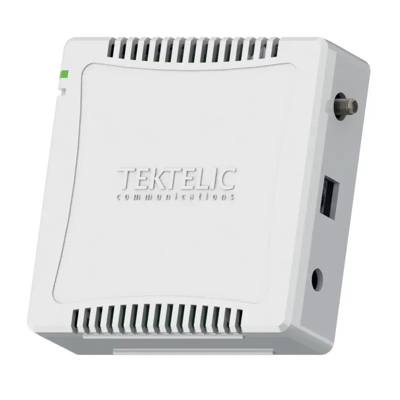
The Kona Micro Gateway is a LoRaWAN IoT gateway that supports the full range of LoRa WAN channels. The Gateway supports one external LoRa antenna, copper Ethernet backhaul, and optional 3G/4G wireless backhaul. All Gateway models are powering from an AC-DC power adapter and may optionally have an internal backup battery provisioned.
Table 1 presents the currently available Kona Micro Gateway models. Any model may have a backup battery provisioned.
Table 1: Kona Micro Gateway Models
| Model | Modem | Region | Frequency Band |
| T0004855 | ü | North America | 915 |
| T0006271 | ü | North America | 915 |
| T0005204 | North America | 915 | |
| T0006342 | North America | 915 |
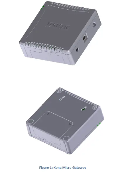
Figure 1 illustrates the Kona Micro Gateway external form-factor with the front view on the top and rear view on the bottom. All models share the same mechanical form-factor.
Physical Interfaces
Figure 2 illustrates the connector layout for the Kona Micro Gateway
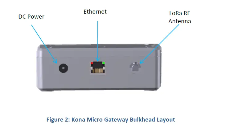
The Gateway connectors are listed in Table 2.
Table 2: Kona Micro Gateway Interface Connector Types
| Interface | Connector Type | Mating Connector |
| LoRa Antenna Ports | Reverse SMA female | Industry standard Reverse SMA male |
|
DC Power Input Port |
Barrel Jack | DC Barrel plug 2.1 mm (inner), 5.5 mm (outer) Center positive
|
| Ethernet Port | RJ-45 | Industry standard RJ45 plug |
Specifications
The Kona Micro Gateway specifications are listed in Table 3.
Table 3: Kona Micro Gateway Specifications
| Attribute | Specification |
| Dimensions | 120 (L) x 118 (W) x 41.5 (H) mm |
| Weight | 336 g (0.74 lbs) with battery, 245 g (0.54 lbs) without battery |
| Operating Temperature | 0°C to 40°C without battery 0°C to 38°C with battery |
| Relative Humidity | 5 to 95 %RH |
| Operating Altitude | -60 m to 4,000 m (-197 ft to 13,123 ft) |
| Power Input | 12 VDC +/-10% |
| Power Consumption | 12 W DC maximum |
| Battery | 7.4 V Lithium Ion |
| Ingress Protection | use only |
| Regulatory Compliance | IEC 62368-1, EN 62368-1, CE FCC Pt. 15, RSS-247, EN 301 489-1 |
Installation
Overview
- The Kona Micro Gateway is intended for indoor use only.
- The Kona Micro Gateway has no internal field serviceable parts other than the battery. Other than installing or replacing the battery, the Gateway module must only be opened by an approved TEKTELIC service center.
- All installation practices must be in accordance with the local and national electrical codes.
- Ensure that the Kona Micro Gateway is located to eliminate any physical hazard to people or property.
- The Kona Micro Gateway shall be powered from the supplied AC-DC power adaptor.
- Do not cover the Gateway or in any way obstruct airflow through the enclosure openings.
- The Kona Micro Gateway may as an option contain a built-in battery. The Gateway may continue to operate after the DC power connection is removed. To completely power down the Gateway when optional battery backup is present, both the DC power source and the battery must be disconnected.
- If the battery needs replacement, use only a replacement battery provided by Tektelic Communication Inc. After battery installation, ensure that the battery cover is secured using the supplied battery cover securement screws. Dispose of old batteries in accordance with regulatory requirements.
Unpacking and Inspection
The following should be considered during the unpacking of a new Kona Micro Gateway.
- Inspect the shipping carton and report any significant damage to TEKTELIC.
- Unpacking should be conducted in a clean and dry location when possible.
- Do not discard the shipping box or foam inserts as they will be required if a unit is returned for repair or re-configuration.
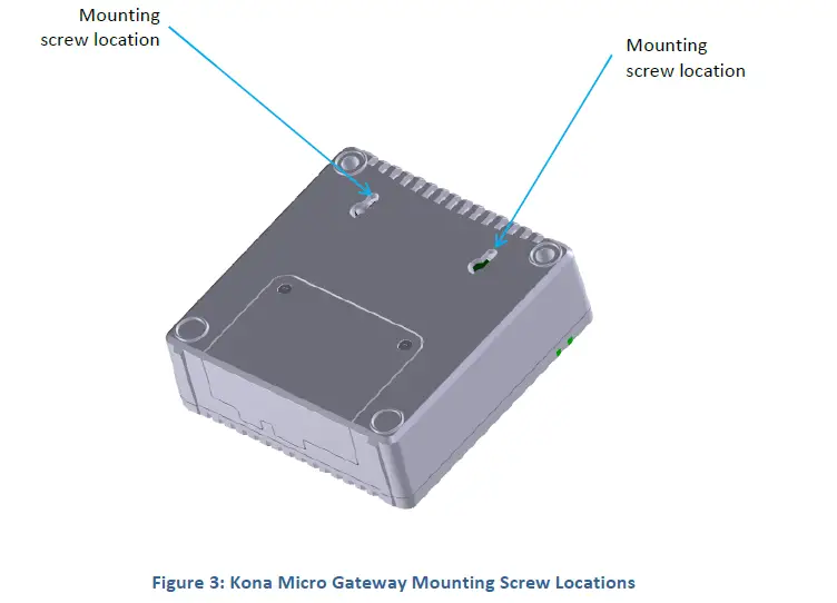
Kona Micro Gateway Mounting
Kona Micro Gateway can be placed on a flat surface or can be mounted to a wall with M3 screws to locations on the back of the module illustrated in Figure 3.
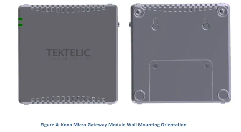
While wall mounted, the Gateway module must be oriented with the TEKTELIC logo horizontal, parallel to the earth as shown in Figure 4.
Ensure that the wall on which the Gateway is being mounted is secure, flat and able to support a load of at least 0.5 kg (1.1 lbs).
The Kona Micro Gateway wall mounting procedure is as follows:
- Install the M3 screws into the wall.
- Install 2 site supplied M3 screws into the wall at 60 mm (2.4”) center spacing, leaving the screw heads protruding with a 3 mm gap from the wall surface.
- Hang the Kona Micro Gateway by mounting the two to keyhole slots onto the screws.
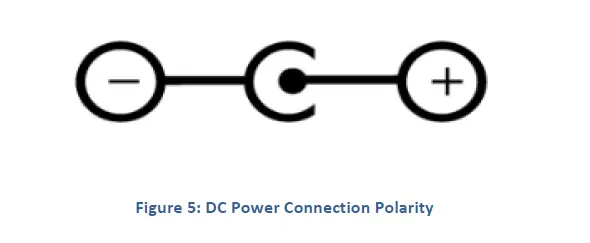
DC Power Cable Installation
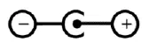
The Kona Micro Gateway is powered from the supplied AC-DC power adaptor. The adaptor provides 12 VDC with positive inner tip as shown below in Figure 5. The connector tip is a standard DC Barrel connector straight plug with 2.1 mm (inner), 5.5 mm (outer) diameters.
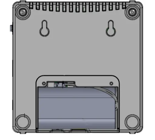
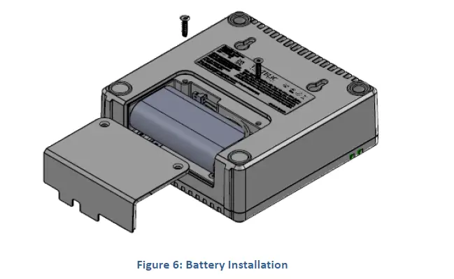
Battery Installation
Use only a battery provided by Tektelic Communications Inc. Dispose of old batteries in accordance with regulatory requirements. Remove the battery cover by removing the two Torx-drive battery cover securement screws. Connect the 3-pin battery connector to the connector at the bottom of the battery compartment and then insert the battery into the battery compartment as illustrated in Figure 6. After the battery is connected and inserted, reinstall the battery cover and secure it in place using the two battery cover securement screws.
RF Cable Installation
The Kona Micro Gateway installation requires connection to a LoRa RF antenna. The antenna attaches to the reverse SMA connector located on the side of the Gateway. Torque the connector to 5 in·lbs. The Kona Micro is not protected from lighting surge as it is intended for Indoor use. Do not connect to an outdoor antenna.
Note that the 3G/4G modem antenna is internal to the Kona Micro Gateway.
Copper Ethernet Cable Installation
The Kona Micro Gateway Ethernet port may be used on a temporary basis for commissioning and maintenance or may be permanently connected for backhaul.
The Ethernet cable must have minimum 24 AWG conductors and shall be rated for indoor application according to local and national electrical codes.
Proposition 65 Statement
WARNING: This product can expose you to chemicals including lead, beryllium, cobalt oxide, nickel oxide, carbon black and lithium nickelate & nickel, which is known to the State of California to cause cancer, birth defects or other reproductive harm. For more information, go to www.P65Warnings.ca.gov.


