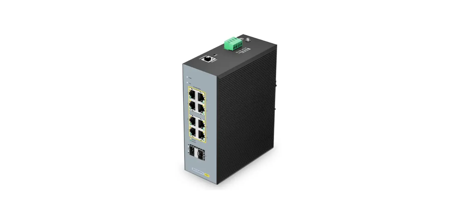

MOB IES3110 Series Industrial PoEplus Switch
Introduction
Thank you for choosing IES3110 Series industrial PoE+ Switch. This guide is designed to familiarize you with the layout of the switch and describes how to deploy the switch in your network.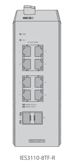
Accessory
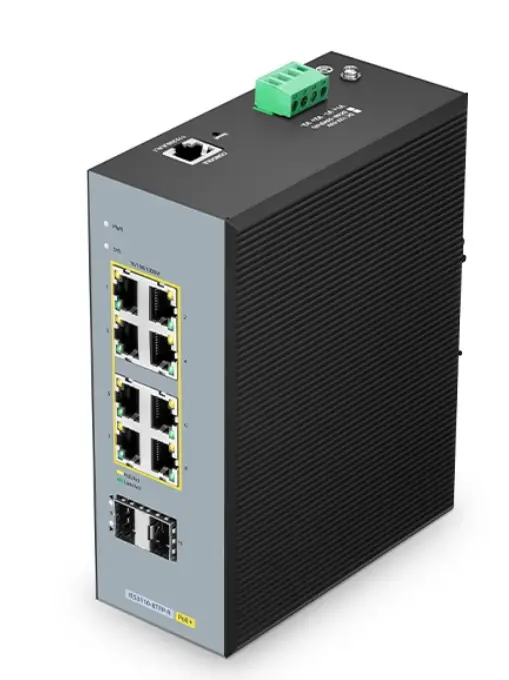
IES3110-8TF-R/IES3110-8TFP-R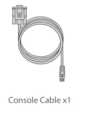
Hardware Overview
Front Panel Ports
IES3110-8TF-R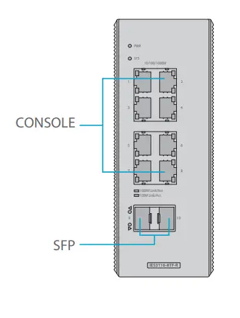
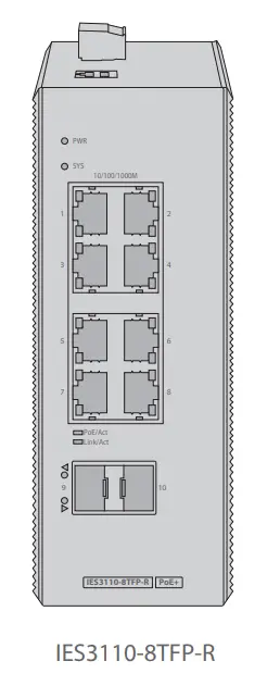
IES3110-8TFP-R
| Ports | Description |
| SFP | SFP ports for 100M/1G/2.5G connection. |
| CONSOLE | A RJ45 console port for serial management. |
Front Panel LEDs
IES3110-8TF-R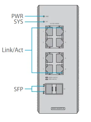
IES3110-8TFP-R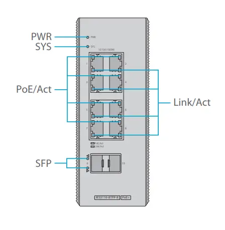
| Indicator | State | Description |
| PWR | On | Powered. |
| Off | No Power. | |
| SYS | On | System is operating normally. |
| Off | System is not running. | |
| POE/Act | On | 1000M Link. |
| Off | 10/100M Link. | |
|
Link/Act | Slow Blinking | 10/100/1000 Link normally. |
| Off | Link disconnect. | |
| Blinking | Link data transmission. | |
|
SFP | On | Fiber connection is normal. |
| Off | Disconnect. | |
| Blinking | Link data transmission. |
Upper Panel
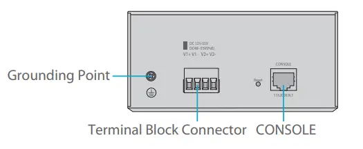
Rear Panel
Installation Requirements
Before you begin the installation, make sure that you have the followings:
- Metropolitan area fiber broadband network: telecommunications, cable TV, network system integration, etc., network operators.
- Broadband private network: Suitable for financial, government, oil, railway, electric power, public security, transportation, education and other industries.
- Multimedia transmission: image, voice, data integrated transmission, suitable for remote teaching, conference TV, videophone and other applications.
- Real-time monitoring: simultaneous transmission of real-time control signals, images, data.
- Resistant to harsh environment: Suitable for strong electromagnetic interference, networking in harsh environments at long distances.
Mounting the Switch
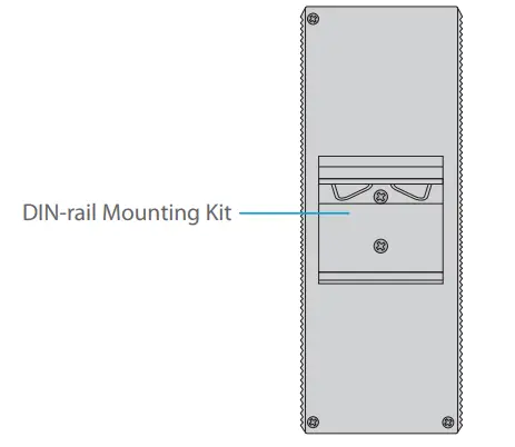
DIN-Rail Mounting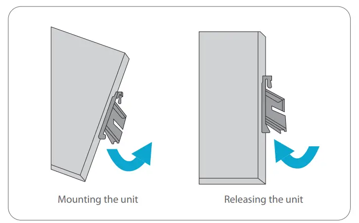
- Hook the mount bracket over the top of the rail.
- Rotate the switch downward towards the rail to lock it into place until the click is heard.
- Pull down to clear the bottom of the DIN-Rail and rotate away from the rail.
Grounding the Switch
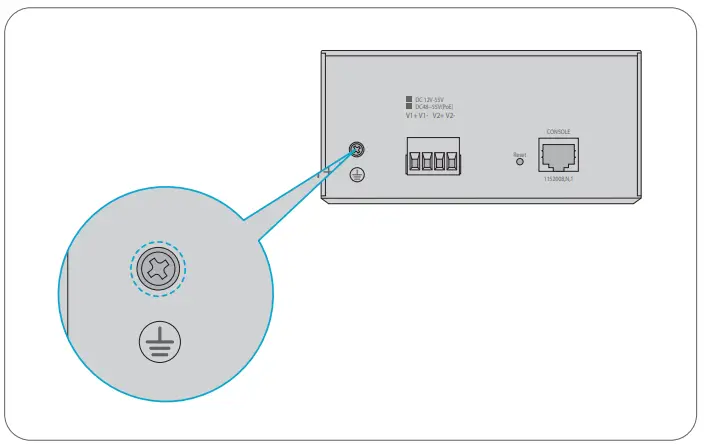
- Connect one end of the grounding cable to the switch.
- Connect the other end of the grounding cable to the earth ground.
Connecting the Power
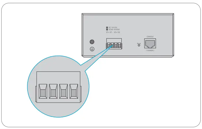
- Connect one end of the power cable to the switch.
- Connect the other end of the power cable to the power supply.
Connecting the RJ45 Ports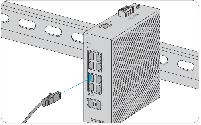
- Connect an Ethernet cable to the RJ45 port of a camera, outdoor AP, computer or other network device.
- Connect the other end of the Ethernet cable to the RJ45port of the switch.
Connecting the SFP Ports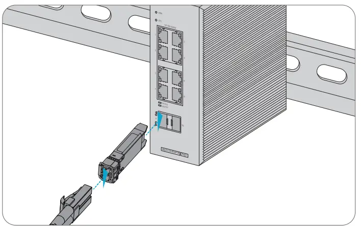
- Plug the compatible SFP transceiver into the SFP port.
- Connect a fiber optic cable to the fiber transceiver. Then connect the other end of the cable to another fiber device.
Connecting the Console Port
- Insert the RJ45 console port on the front of the switch.
- Connect the DB9 female connector of the console cable to the serial port on the computer.
Configuring the Switch
Configuring the Switch Using the Web-based Interface
- Step1: Connect the computer to any RJ45 port of the switch using the network cable.
- Step2: Set the IP address of the computer to 192.168.1.X (“x” is any number from 1 to 254)
- Step3: Open a web browser, enter the default IP address of the switch 192.168.1.1, and enter the default username and password, admin/admin. Step4: Click Login to display the web-based configuration page.
Configuring the Switch Using the Console Port
- Step1: Connect a computer to the switch’s console port using the console cable.
- Step2: Start the terminal simulation software such as HyperTerminal on the computer. Step3: Set the parameters of the HyperTerminal:9600 bits per second, 8 data bits, no parity, 1 stop bit, no flow control.
- Step4: After setting the parameters, click Connect to enter.
Troubleshooting
100M/1G/2.5G Port is not working
- Ensure the optical module and cable have no problem.
- Check if the configuration at both ends of the communication device is auto or forced rate.
Connecting the Switch Remotely Unsuccessfully
- Test network connectivity through ping.
- If the network is reachable, try restarting the switch.
- Check if the corresponding service is enabled.
The Port is not Working, the LED indicator is off
- Ensure the switch ports are in the no shutdown state.
- Check if the switch can read the DDM information.
- Check if the port speed setting is correct.
- Try looping the switch cable.
RJ45 port is not in connectivity, or it is erroneous in receiving/transmitting frames
- Replace the twisted pair cable.
- Check that the port configuration has the common working mode with the connected switch.
Online Resources
- Download https://www.fs.com/products_support.html
- Help Center https://www.fs.com/service/fs_support.html
- Contact Us https://www.fs.com/contact_us.html
Product Warranty
FS ensures our customers that any damage or faculty items due to our workmanship, we will offer a free return within 30 days from the day you receive your goods. This excludes any custom-made items or tailored solutions.
Warranty: IES3110 series switch enjoys 5 years limited warranty against defect in materials or workmanship. For more details about warranty, please check at https://www.fs.com/policies/warranty.html
Return: If you want to return item(s), information on how to return can be found at https://www.fs.com/policies/day_return_policy.html


