FS IES3110-8TF L2+ Managed Industrial Switch
Introduction
Thank you for choosing IES3110-8TF Managed Switch. This guide is designed to familiarize you with the layout of the switch and describes how to deploy the switch in your network.
Accessories
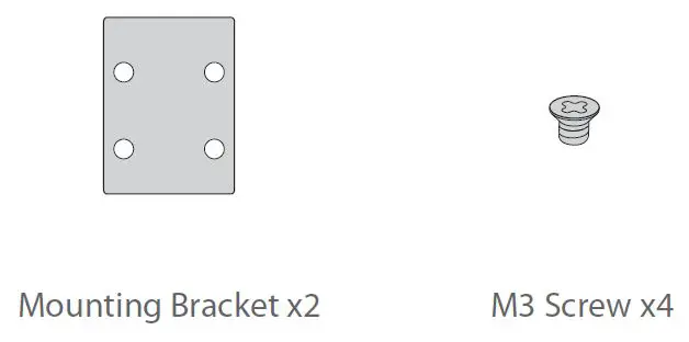
NOTE: IES3110-8TF switch has dust plugs delivered with it. Keep the dust plugs properly and use them to protect idle ports.
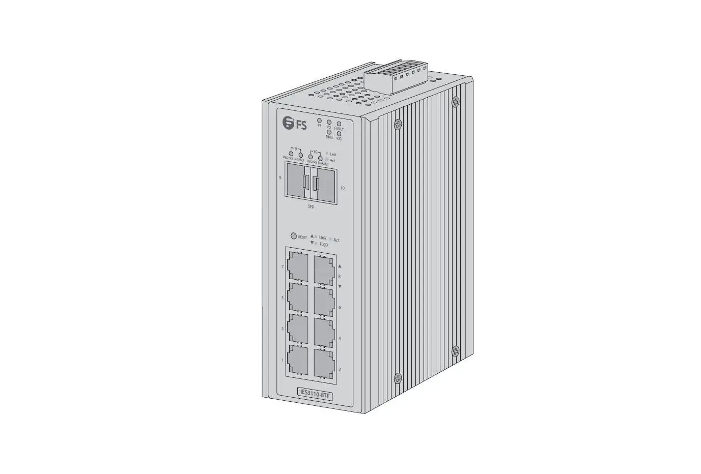
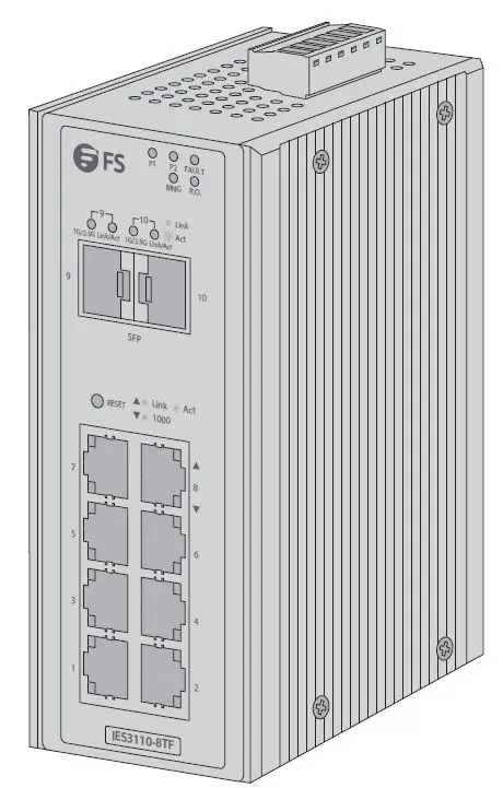
Hardware Overview
Front Panel Ports
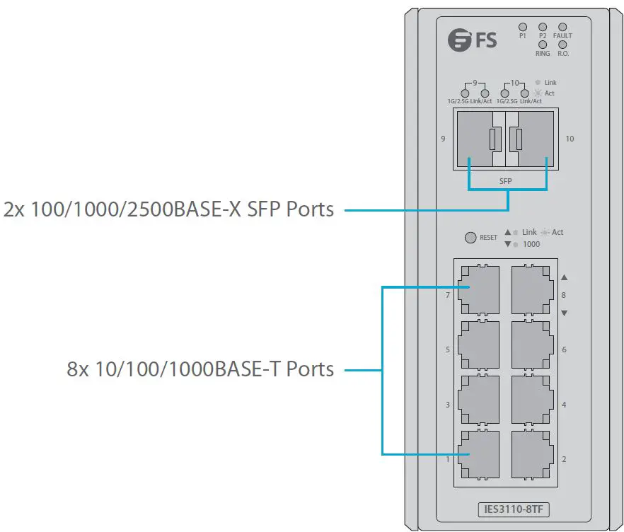
| Ports | Description |
| RJ45 | 10/100/1000BASE-T ports for Ethernet connection |
| SFP | SFP ports for 100M/1G/2.5G connection |
Upper Panel
Rear Panel
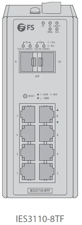
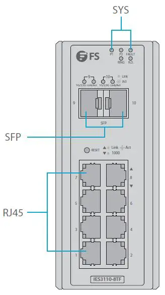
Front Panel LEDs
| LEDs | Status | Description | ||
|
SYSTEM | P1 | Green | Indicates the Switch has power. | |
| P2 | Green | Indicates the Switch has power. | ||
| Fault | Green | Indicates power failure. | ||
| Ring | Green | Indicates that the ERPS Ring has been created successfully. | ||
| R.O. | Green | Indicates that Switch has been enabled to Ring Owner. | ||
|
RJ45 |
LINK/ACT |
Green | Light | Indicates the link through that port is successfully established. |
| Blink | Indicates that the Switch is actively sending or receiving data over that port. | |||
|
1000 |
Orange | Light | Indicates that the port is successfully connecting to the network at 1000Mbps. | |
| Off | Indicates that the port is successfully connecting to the network at 10Mbps or 100Mbps. | |||
|
SFP |
LINK/ACT |
Green | Light | Indicates the link through that port is successfully established. |
| Blink | Indicates that the Switch is actively sending or receiving data over that port. | |||
|
1000 |
Orange | Light | Indicates that the port is successfully connecting to the network at 1000Mbps. | |
| Off | Indicates that the port is successfully connecting to the network at 100Mbps. | |||
Installation Requirements
Before you begin the installation, make sure that you have the following:
- Workstations running Windows XP/2003/Vista/7/8/10/2008, MAC OS X or later, Linux, UNIX, or other platforms are compatible with TCP/IP protocols.
- Workstations are installed with Ethernet NIC (Network Interface Card).
- Ethernet Port Connection Network cables — Use standard network (UTP) cables with RJ45 connectors. The above PC is installed with Web browser.
NOTE: It is recommended to use Internet Explorer 8.0 or above to access the switch. If the web interface of the Industrial Managed Switch is not accessible, please turn off the anti-virus software or firewall and then try it again.
Mounting the Switch
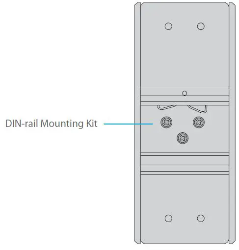
DIN-Rail Mounting
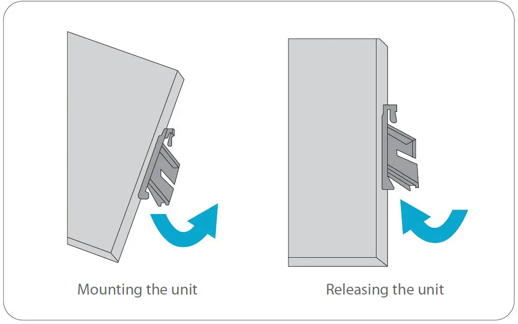
- Position the unit in front of the DIN-Rail and hook the mount bracket over the top of the rail.
- Rotate the switch downward towards the rail to lock it into place. You will know it is secure when you hear the click.
- To remove the unit, pull down to clear the bottom of the DIN-Rail and rotate away from the rail.
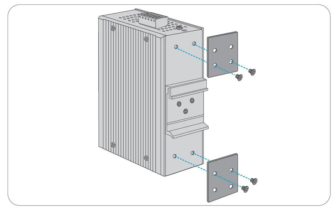
Wall Mounting
Screw on the mounting bracket on the switch with M3 screws.
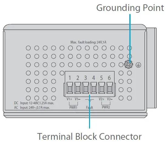
Grounding the Switch
Grounding and wire routing help limit the effects of noise due to electromagnetic interference (EMI). Run the ground connection from the ground screw to the grounding surface prior to connecting devices.
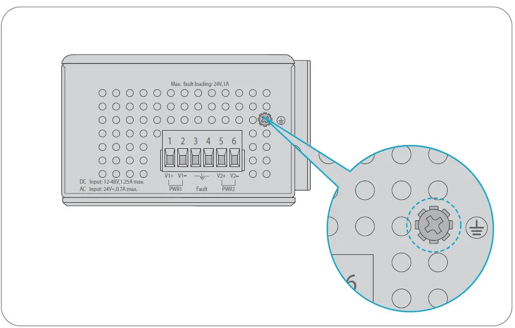
NOTE: This product is intended to be mounted to a well-grounded mounting surface such as a metal panel.
Connecting the Power
The Upper Panel of the switch indicates an AC/DC inlet power socket and consists of one terminal block connector within 6 contacts. Please follow the steps below to insert the power wire. Insert positive/negative AC or DC power wires into Contacts 1 and 2 for Power 1, or Contacts 5 and 6 for Power 2.
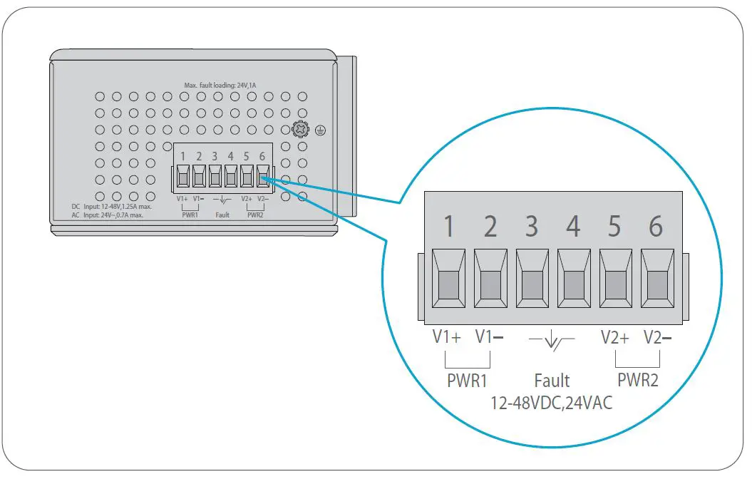
| No. | Name | Description |
| 1 | V1+, V2+ | Live line/Positive |
| 2 | V1-, V2- | Null line/Negative |
| 3 | Requiring good ground connection |
Tighten the wire-clamp screws for preventing the wires from loosening.
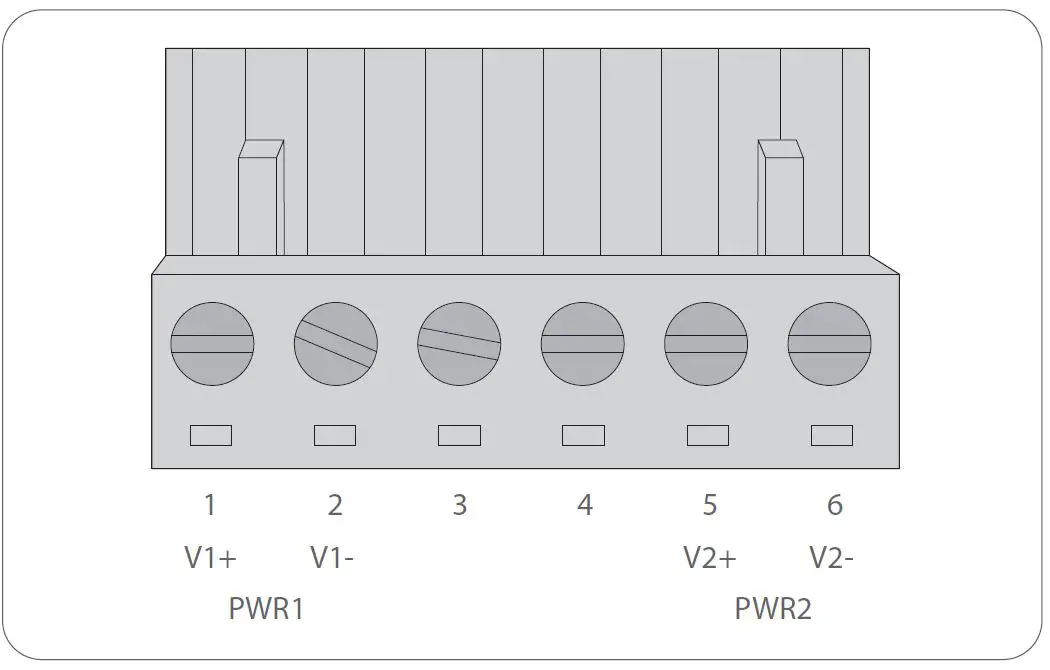
| Positive (+) Pin | Negative (-) Pin |
| Pin 1 / 5 | Pin 2 / 6 |
NOTE: The wire gauge for the terminal block should be in the range from 12 to 24 AWG.
Connecting the RJ45 Ports

- Connect an Ethernet cable to the RJ45 port of a camera, outdoor AP, computer or other network device.
- Connect the other end of the Ethernet cable to the RJ45 port of the switch.
Connecting the SFP Ports
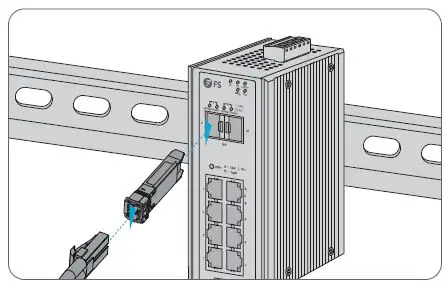
- Plug the compatible SFP transceiver into the SFP port.
- Connect a fiber optic cable to the fiber transceiver. Then connect the other end of the cable to another fiber device.
Configuring the Switch
Configuring the Switch Using the Web-based Interface
Step 1: Connect the computer to any RJ45 port of the switch using the network cable.
Step 2: Set the IP address of the computer to 192.168.1.x (“x” is any number from 2 to 255).
Step 3: Open a web browser, enter the default IP address of the switch 192.168.1.1, and enter the default username and password, admin/admin.
Step 4: Click Login to display the web-based configuration page.
Troubleshooting
100M/1G/2.5G Port is not Working
- Ensure the optical module and cable have no problem.
- Check if the configuration at both ends of the communication device is auto or forced rate.
Connecting the Switch Remotely Unsuccessfully
- Test network connectivity through ping.
- If the network is reachable, try restarting the switch.
- Check if the corresponding service is enabled.
The Port is not Working, the LED Indicator is Off
- Ensure the switch ports are in the no shutdown state.
- Check if the switch can read the DDM information.
- Check if the port speed setting is correct.
- Try looping the switch cable.
RJ45 port is not in connectivity or it is erroneous in receiving/transmitting frames
- Replace the twisted pair cable.
- Check that the port configuration has the common working mode with the connected switch.
Support and Other Resources
- Download https://www.fs.com/products_support.html
- Help Center https://www.fs.com/service/fs_support.html
- Contact Us https://www.fs.com/contact_us.html
Product Warranty
FS ensures our customers that any damage or faulty items due to our workmanship, we will offer a free return within 30 days from the day you receive your goods. This excludes any custom made items or tailored solutions.
Warranty: IES3110-8TF switch enjoy 5 years limited warranty against defect in materials or workmanship. For more details about warranty, please check at https://www.fs.com/policies/warranty.html
Return: If you want to return item(s), information on how to return can be found at https://www.fs.com/policies/day_return_policy.html
References
 FS.com - Data Center, Enterprise, Telecom
-
Quality Certification - FS.com
-
Ein weltweit führender Anbieter von Hochgeschwindigkeits-Konnektivitätsgeräten und -lösungen. - FS.com Deutschland
-
FS.com - Data Center, Enterprise, Telecom
-
Contact Us - FS.com
-
Kontakt - FS.com Deutschland
-
Rückgaberecht - FS.com Deutschland
-
Ein weltweit führender Anbieter von Hochgeschwindigkeits-Konnektivitätsgeräten und -lösungen. - FS.com Deutschland
-
Technische Dokumente - FS.com Deutschland
-
Hilfezentrum - FS.com Deutschland
-
Fournisseur leader de solutions et matériels de connectivité à haut débit - FS.com France
-
Comment Nous Contacter - FS.com France
-
Politique de retour - FS.com France
-
Fournisseur leader de solutions et matériels de connectivité à haut débit - FS.com France
-
Documents techniques - FS.com France
-
Centre d'aide - FS.com France
-
Return Policy - FS.com
-
Products Warranty - FS.com
-
Technical Documents - FS.com
-
Help Center - FS.com


