Lindab CARAT Passive Chilled Beam
 Installation instruction
 Installation instruction
Mounting Instruction Carat – Passive chilled beam
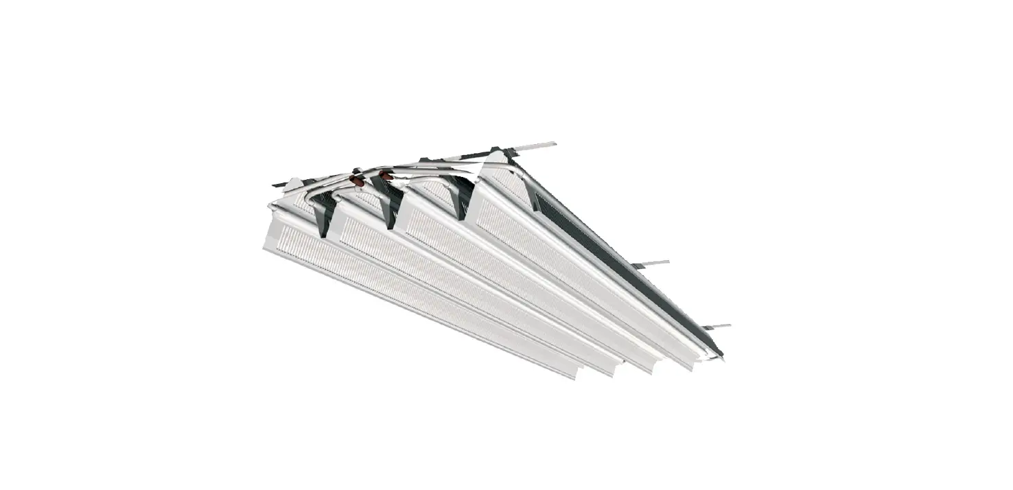
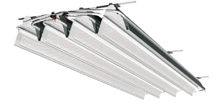
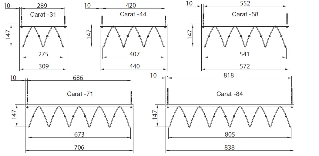
The following guidelines are intended to assist the installer, and should not obviate good working practices. There are five different models of Carat available; 31, 44, 58, 71 and 84.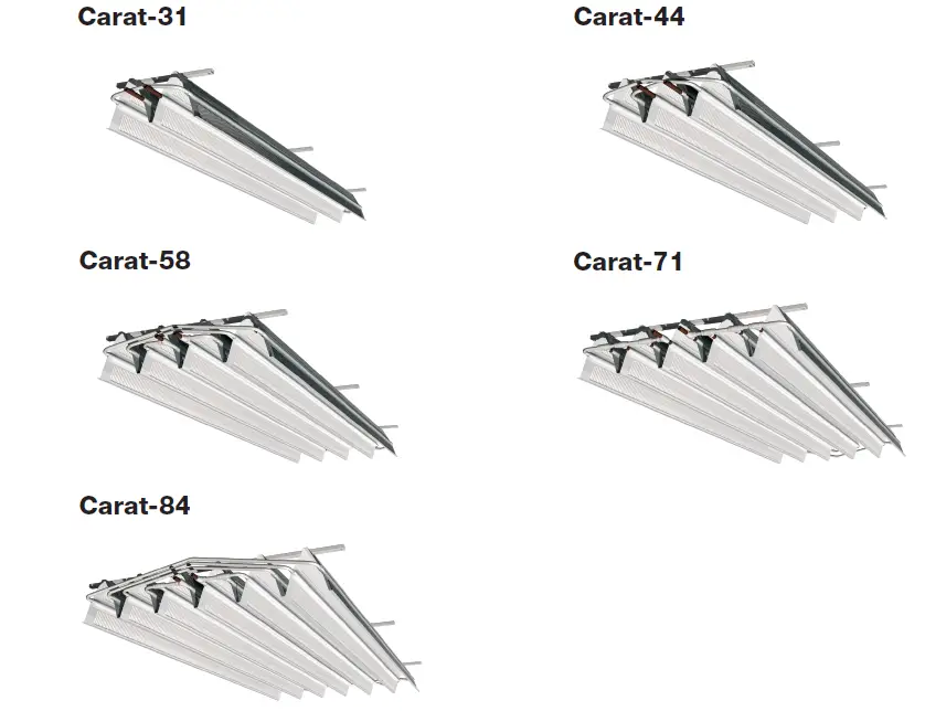
Product Labelling
Delivery Coding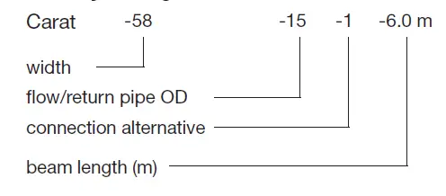
Beams are also supplied with support sleeves as standard, plus any optional items as specified in the documentation (special colour, control valves, condensation sensors etc.).
Suspension
As standard, Carat is available in lengths from 1.8 m to 6.0 m, in steps of 0.1 m. 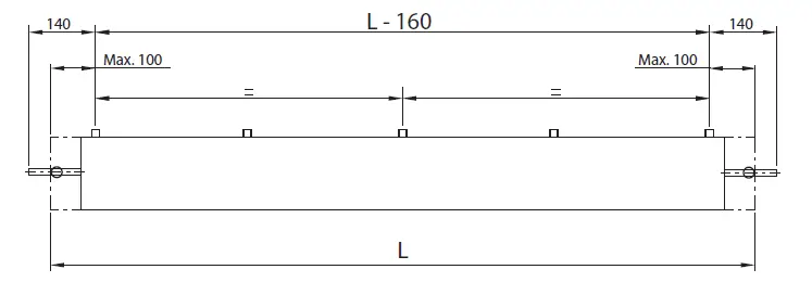
3 × 2 suspension points for lengths > 3 m.
When connecting the chilled beam to the flow and return pipework, it is most important to fit the copper support sleeve to ensure that the chilled beam connection pipes are not crushed during installation. Also, it must be remembered that connections must be of a compression, push-fit or press-fit type. Connections to the chilled beam MUST NOT be soldered. Ensure the allowance is made for possible expansion/contraction of the main water work (using expansion loops or bellows).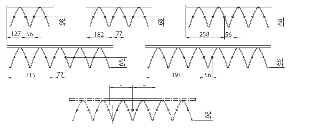
Installation
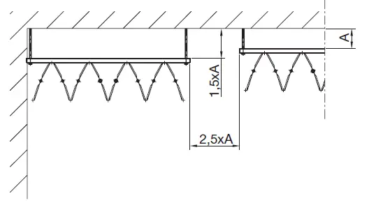
In order for Carat to deliver the stated cooling capacity, it is important to maintain specified distances to the structural soffit, walls, and adjacent product.
The distances identified below are minimum acceptable, and vary depending upon product width: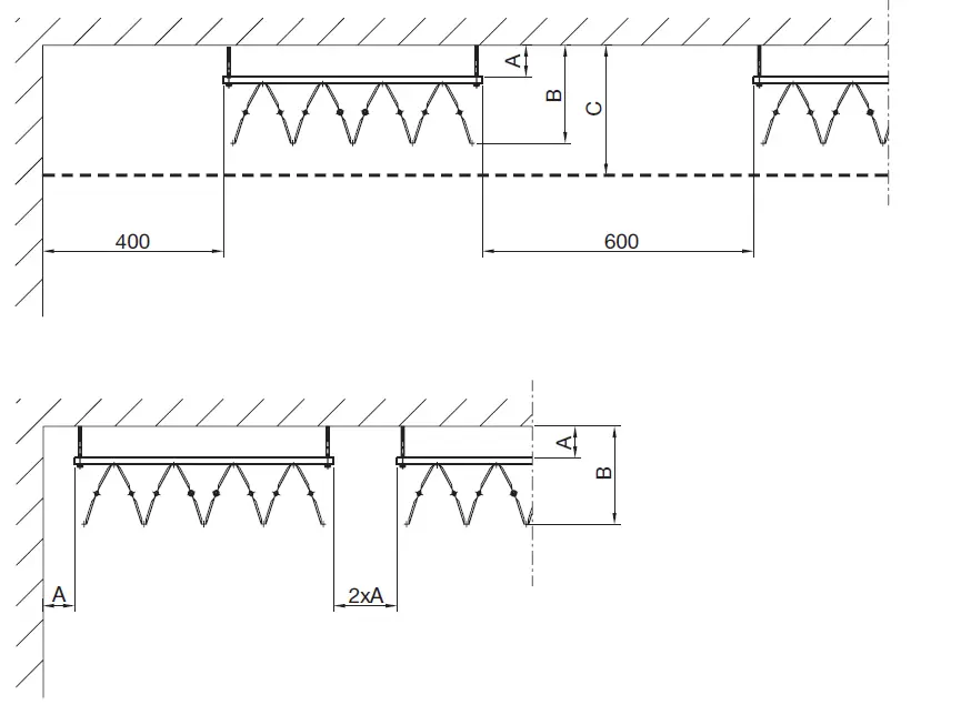
| Model | A (mm) | B (mm) | C (mm) |
| Carat -31 | 45 | 192 | 232 |
| Carat -44 | 55 | 202 | 252 |
| Carat -58 | 70 | 217 | 267 |
| Carat -71 | 85 | 232 | 302 |
| Carat -84 | 105 | 252 | 322 |
Aesthetic

The free-hanging chilled beam appears slightly different when viewed from different directions – this is due to the punched cooling fins on the surface of the product. This difference in aesthetics should be considered when designing the connection position for each chilled beam. The diagram above illustrates that it is possible to have the cooling fins facing the same direction, but with horizontal pipe connections at different ends.
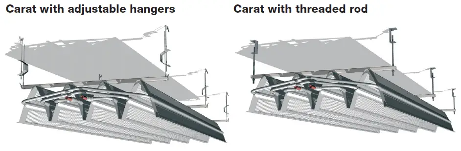
Installation Procedure
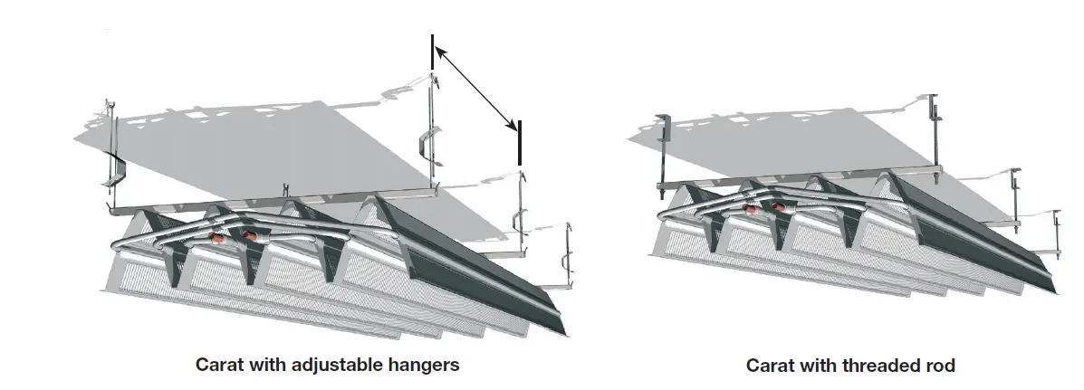
Measure the distance between the suspension points and mount the chosen fixing to the roof. Put adjustable hangers or threaded rod through the pre-drilled holes in the aluminium suspension bars/suspension brackets. Lift up the product using the hangers and attach the hangers/rods to the soffit fixing. DO NOT lift the chilled beam from any position other than the aluminum suspension bars or attached hangers.
Adjust the beam’s vertical position according to the diagram on page 4. If necessary shorten the hangers/rods to appropriate lengths.
Hangers/rods should be secured to ensure that they do not come loose from either the soffit fixing or the chilled beam. Hangers should be secured by bending over the hanger end loops at either end, threaded rods by using 4 nuts for each rod – above and below the soffit fixing and again above and below the aluminum bar/bracket. Don’t forget to tighten your nuts.
It is important to remember to fit the copper support sleeves into the water connection pipes before connecting the compression, press-fit or push-fit couplings. NOTE! DO NOT SOLDER! Ensure that allowance is made for possible expansion/contraction of the mains water pipework (using expansion loops or bellows).
Where plastic connections or flexible hoses are used, it is important to ensure that these products are designed to be resistant to oxygen penetration.
Ensure that the distribution pipework is flushed and cleaned in isolation of the chilled beam. Do not remove protective pipe caps until just before connection to the flushed distribution pipework.
Handling
NEVER handle the product from the extreme edges or from the pipe tails.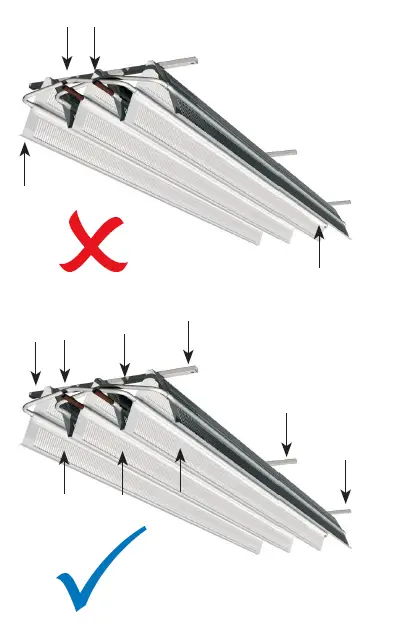
ALWAYS handle the product from either the suspension bar, the pipe mani-fold or the bottom of the ‘A’ profile. Take care not to damage cooling fins or pipe tails.
Support
Here you can find product updates/mounting instructions and support telephone number/mail. www.lindab.com
Right to alterations reserved.
Do you have trouble finding your local contacts please go to:
www.lindab.com


