Mercoid D Series Pressure Controls with Mercury Switches Instruction Manual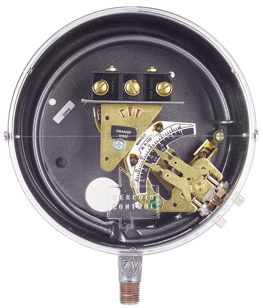
Instructions
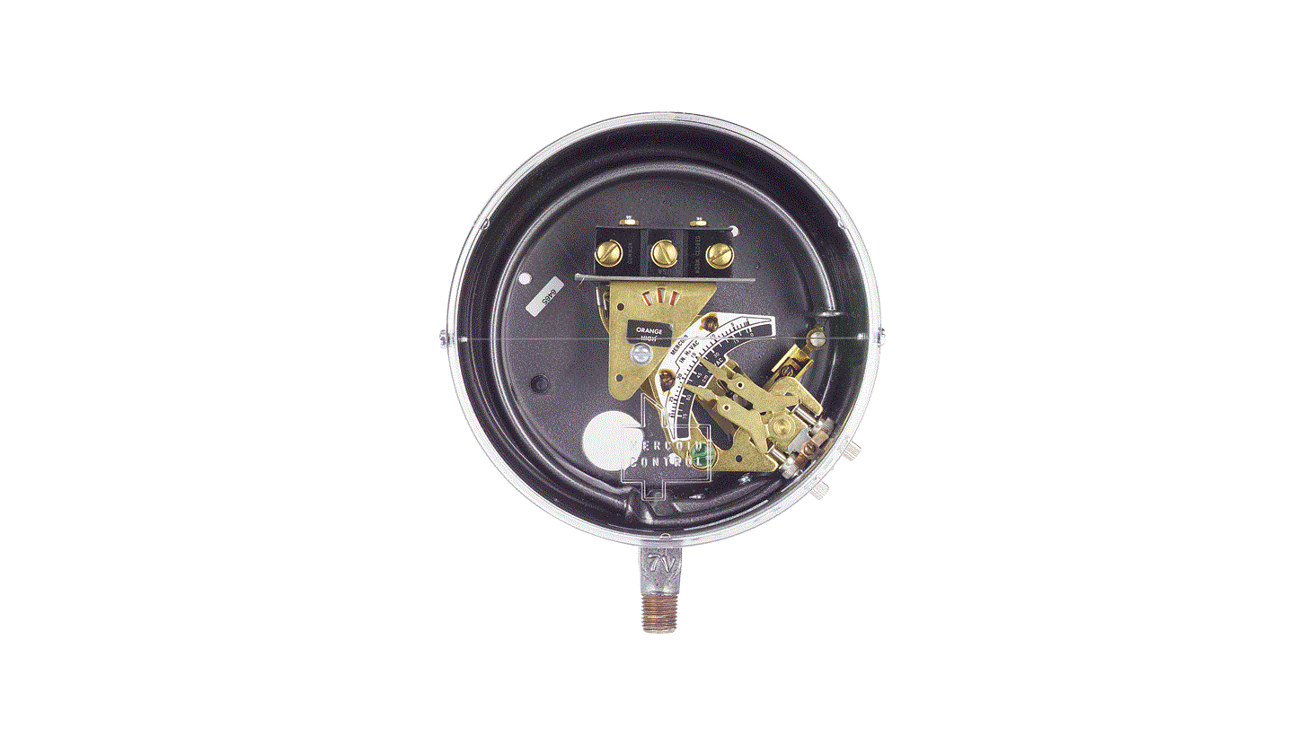
General purpose
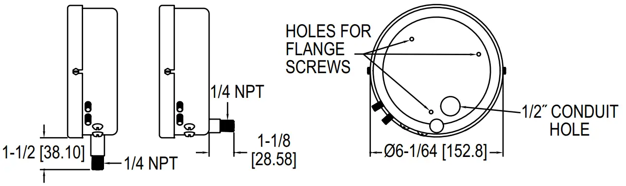
General purpose with flange for surface mounting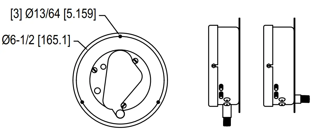
Mercoid Series “D” Pressure Controls Bourdon tube power elements, visible setpoint, adjustable deadband or fixed deadband and pressure ranges from 0 to 30 in Hg VAC to 800 to 8000 psig (345 bar).
BENEFITS/FEATURES
- Visible calibrated dial
- On/off indication
- Adjustable, fixed deadband, or manual reset
- External switch setpoint adjustments
- Minimum deadband is obtainable at any point in the range
- Pressure Ranges of full vacuum to 8000 psig.
- UL listed, CSA approved. Many models FM approved.
- General purpose, weatherproof or explosion-proof enclosures
- Single or two stage operation
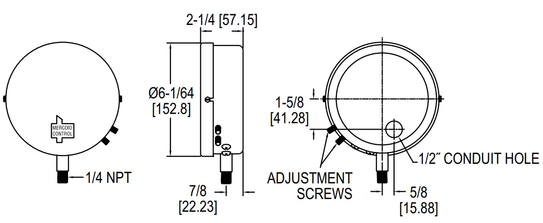
Location and Mounting
Select a location that is recommended by equipment manufacter and reasonably free from vibration caused by reciprocating or rotating machinery. Where excessive vibration occurs, use a remote connection and mount by means of a mounting bracket or separable flange (available on order). When in doubt about excessive vibration, use a remote connection. Where pulsations, pres-sure surges, or water hammer are present, protect the control with a surge tank or scrubber. Mount all controls vertically and level.
General Purpose Controls: Install controls prefixed by the let-ters DA, DAF, DRF, DL, DS, DSF, firmly in a level position. Do not mount the control by twisting the case; use a wrench on the square part of the 1/4˝ bottom pipe connection. To level, sight across the two cover screws or check the lower end of the glass opening in the cover to see that the control is lined up horizontal-ly. On general purpose controls provided with a flange, mount by means of the three holes in the flange.
SPECIFICATIONS
Wetted Materials: Brass, 403 SS, or 316 SS.
Temperature Limit: 180°F (82°C).
Pressure Limit: Maximum pressure of the operating range. Enclosure rating: General purpose, weatherproof or explosion-proof.
Repeatability: ±1% of full operating range.
Switch Type: See circuit chart.
Electrical Rating: See electrical ratings chart.
Electrical Connections: Screw terminal.
Conduit Connection: General purpose: 1/2˝ hole for conduit hub. Weatherproof: 1/2˝ conduit hub. Explosion-proof: 3/4˝ female NPT.
Process Connection: General purpose and weatherproof: 1/4˝ male NPT, 1/2˝ male NPT on ranges 15S and 16S. Explosion-proof: 1/2˝ male NPT and 1/4˝ female NPT.
Mounting Orientation: Vertical.
Set Point Adjustment: Thumbscrew.
Weight: General Purpose: 4 lb (1.8 kg), weatherproof: 6 lb (2.7 kg), explosionproof: 8 lb (3.5 kg).
Deadband: See ranges and differentials chart.
ACCESSORIES
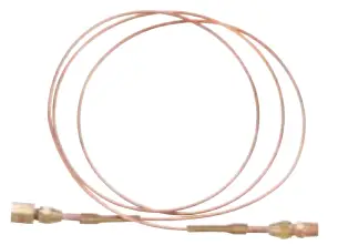 Remote Connection No. 49-62 (300 psi) No. 49-62HP (to 2500 psi) | 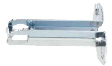 Mounting Bracket No. 33-25 | 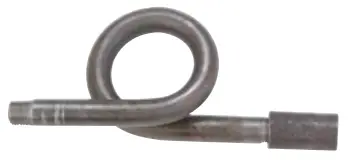 Pigtail Siphon No. 42-52 (300 psi) No. 42-58 (2,000 psi) |
General Watertight or Weather-Resistant Types: These controls are prefixed by the letters DAW, DRW, DSW and DLW. They are supplied with flanged case, bottom connection only, for surface mounting. Again, install firmly in a level position. Do not mount the control by twisting the case; use a wrench on the square part of the 1/4˝ bottom pipe connection. Be sure pipe connection is in a vertical position. After cover is properly attached, with the name plate on bottom of the cover, sight across the lower end of the glass opening in the cover to see that the control is lined up vertically.
Do not use holes in case bottom for mounting.
Explosion-Proof Types: Install controls prefixed by the letters DAH, DAHF, DRH, DSH, DAE, DRE, DSE, firmly in a level position by means of mounting lugs attached to the control housing. Line up horizontally by sighting across the left and right conduit hubs.
Note: Series D-30, D-230, D-430, D-530 (i.e., DA-31-3, etc.), when used for steam with operating ranges of 35 psi or higher, must be siphoned to prevent live steam from entering the Bourdon tube. With high pressure steam in excess of 100 psi, use a remote connection.
Series D-20, D-220, D-420, D-520 (i.e., DA-21-2, etc.), when incorpo-rate an orifice as standard in the bottom stem to dampen out surges or pul-sations.
WIRING
Wire in accordance with local electrical codes or equipment manufacturer’s instructions.
For general purpose controls, use a short piece of BX between the rigid conduit and the control so that it will not be subjected to conduit expan-sion and contraction. Where control is directly connected into load circuit, it should be connected into hot side of line. For electrical rating, see name-plate attached to control case.
ADJUSTMENTS
How to Set Operating Point Double Adjustment Types – Fully Automatic
Prefixed by DA, DAF, DAW, DAH, DAHF – provided with double adjustments. Adjust the upper pointer “C” to set the HIGH PRESSURE POINT for switch operation. Adjust the lower pointer “U” to set the LOW U PRESSURE POINT. The differ-ence between the HIGH and LOW pointers is the operating differential between “on-off” switch operation.
Double adjustment types – Fully automatic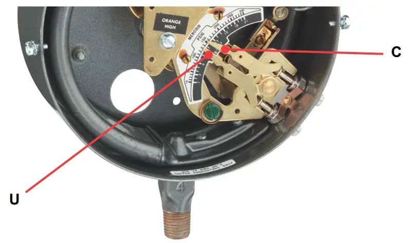
Single Adjustment Types – Fully Automatic
Prefixed by DS, DSE, DSF, DSH -equipped with a single adjustment. The single pointer on the scale sets the pressure where switch operation occurs. Differential is fixed (not adjustable). Example setting: Type DS-21-2, range 0-60 psi: circuit opens on pressure rise. If pointer is set at 40 psi, the control will operate to OPEN circuit at 40 psi and RE-CLOSE circuit at the fixed differential of 4 psi.
Single adjustment types – Fully automatic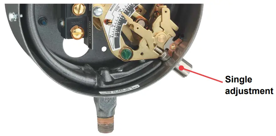
Semi-Automatic Control with Manual Reset
Prefixed by DR, DRF, DRH, DRE, DRW – with suffix -L or -U. Example: Type DR21-2U. A single adjustment sets the operating point for automatic operation. A pushbutton reset must be operated manually to restore the circuit to the original positionafter automatic operation. Example: Type DA-21-2L. Circuit will open automatically on a pressure rise to the pressure indicated by the pointer on the scale. No matter how much the pressure drops, the circuit will not re-close until the reset button has been operated. Suffix -L denotes control will operate automatically on an increase in pressure. Suffix -U denotes control will operate automatically on a decrease in pressure.
Semi-automatic control with manual reset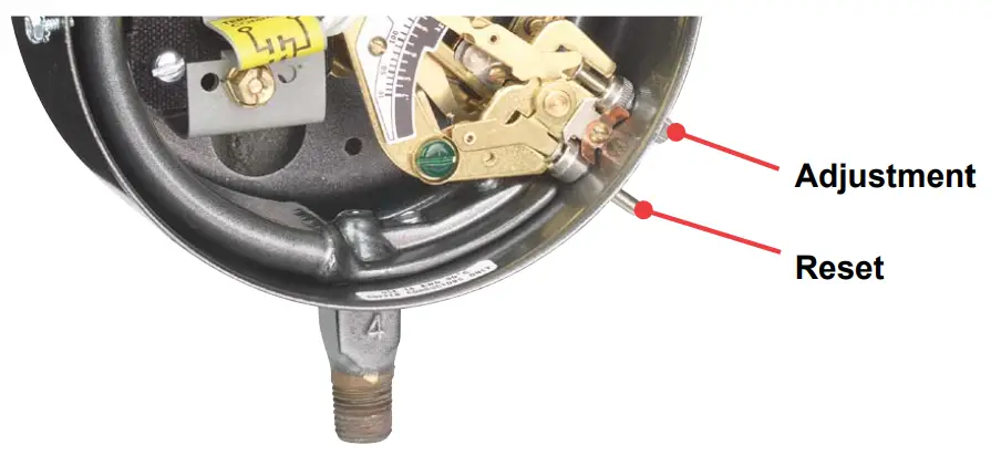
Manual Lock Type Reset Control
Operates automatically on a decrease of pressure with provision for man-ual reset when pressure is below set point. Prefixed by DL, DLW, DLE, DLH. A single adjustment sets the low pressure operating point of the control at any value on the scale range.
The control will operate automati-cally at the set point only on a drop in pressure. The lock-type feature per-mits the circuit to be reset and locked in position when pressures are below control setting. The lock remains in effect until the pressure has risen to a value above the control setting. Lock then releases and the circuit is held in the reset position due to the pressure rise. It will remain in the reset position until it is called on to again operate automatically on a pressure drop to the selected setting.
Manual lock type reset control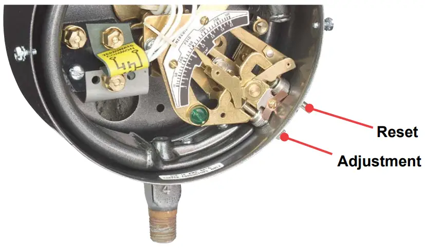
Two-Stage Pressure Controls – Series D-400
Types DA, DAW, DAH, DAE – with suffixes 421, 423, 431, 433, etc., followed by specification numbers 4122, 4123, 4129, 4132.
This series incorporates two single pole, single throw magnetic mercury switches, actuated by the same Bourdon tube. The operating point of each switch is adjustable through an outside adjustment.
The change in pressure which opens and closes each switch at its respective setting is the switch’s fixed differential. The pressure represented by the difference between the two adjustment pointers is the pressure “spread” between operation of the two switches. Upper pointer “U” indicates the operating point of the HIGH pressure circuit.
Lower point “L” indicates the operating point of the low pressure circuit.
Two-stage pressure controls Series 400 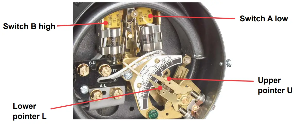
Example Setting: Type DA-421, Specification No. 4122, range 0 to 60 psi. With lower pointer “L” set at 25 psi and upper pointer “U” set at 50 psi, both circuits will be closed when pressure is 25 psi and lower. When pressure rises to 26 psi, mercury switch A will open its circuit. When pressure rises to 50 psi, mercury switch B will open its circuit.
Both switches remain open above this setting. The fixed differential (sensitivity) of each switch for this particular range is 1 psi. Upon a drop in pressure, mercury switch “B” will close its circuit at 49 psi; mercury switch “A” will close its circuit at 25 psi.
LOCKING DEVICE
When the control has been adjusted to desired range, the locking bar may be inserted between the adjustment screws with slot passing over the hole in the lug. By placing a sealing wire between the locking bar and the hole in the lug protruding from the adjustment assembly, adjustments cannot be tampered with.
For DAF, DRF, DSF, DAW, DRW, DSW, the adjusting knob cover may be sealed in place with sealing wire through the cover bolt hole. For DAH, DSH, sealing wire may pass through locking bar and hole in hub above the adjusting knobs.
CAUTION: Do not exceed maximum adjustment/operating range of control. Remove control if higher pressures are required.
CAUTION: Do not fail to use a siphon on steam where range is 35 lb or more. Control movement must not be oiled.
CAUTION: Do not overload — note electrical rating on nameplate and be sure total current passing through switch is within specified rating.
CAUTION: Do not tamper with switch wires. Position of these wires is essential to proper operation. Tampering with these wires will void warranty.
| Controls with Mercury Switches | Adjustable Differential Double Adjustment for setting both ‘on and ‘off” operating points Maximum Differenial – full-scale. Minimum Differential listed below. | Fixed Differenital Single Adjustment Adjustable operating point. Differential fixed NOT ADJUSTABLE | |||
| APPLICATION Bourdon tube Material | Adjustable Operating Range psig | Range Number | DA-31 | DA-531 | DS-231 |
| Brass Bourdon Tubes | 0-30 Hg VAC 10 in Hg VAC 12 1/8 to 15 psig 1/8 to 20 psig 1 to 35 psig 25 in Hg VAC 50 2 to 60 psig 5 to100 psig 5 to 150 psig 10 to 200 psig 10 to 300 psig | 2 3 1 3A 4 27 5 6 7 8 9 | 2˝ Hg 1 psig 1 psig 1 psig 1.75 psig 3.5 psig 3 psig 3.75 psig 6 psig 8 psig 12 psig | 1 in Hg 0.5 psig 0.5 psig 0.5 psig 0.75 psig 2 psig 1 psig 2 psig 3 psig 3.5 psig 6 psig | 0.2 in Hg 2 oz 2 oz 2 oz 4 oz 7 oz 6 oz 7 oz 8 oz 12 oz 16 oz |
| DA-21 | DA-521 | DS-221 | |||
| 403 Stainless Steel Bourdon Tubes | 30 in Hg VAC 60 30 in Hg VAC 75 2 to 60 psig 5 to 100 psig 10 to 200 psig 10 to 300 psig 40 to 350 psig 25 to 600 psig 50 to 1000 psig 100 to 1500 psig 300 to 2500 psig 500 to 5000 psig 800 to 8000 psig | 25S 26S 5S 6S 8S 9S 9AS 10S 11S 12S 13S 15S 16S | 6 psig 8 psig 4 psig 6 psig 8 psig 14 psig 14 psig 25 psig 60 psig 90 psig 150 psig 450 psig 750 psig | 3 psig 4 psig 2.5 psig 3 psig 4 psig 7 psig 7 psig 15 psig 40 psig 50 psig 100 psig 200 psig 400 psig | 12 oz 12 oz 0.5 psig 0.75 psig 0.75 psig 1 psig 1 psig 2.5 psig 10 psig 12 psig 45 psig 150 psig 200 psig |
| DA-41 | DA-541 | DS-241 | |||
| 316 Stainless Steel Bourdon Tubes | 30 in Hg VAC 75 5 to 75 psig 10 to 100 psig 10 to 150 psig 10 to 300 psig 30 to 400 psig 75 to 800 psig 100 to 1000 psig 200 to 2500 psig | 26E 23E 6E 24E 9E 21E 22E 11E 13E | 7 psig 3 psig 7 psig 6 psig 18 psig 30 psig 75 psig 100 psig 210 psig | 35 psig 2 psig 3.5 psig 3 psig 5 psig 15 psig 35 psig 45 psig 110 psig | 14 oz 0.4 psig 14 oz 0.75 psig 3 psig 5 psig 12 psig 18 psig 50 psig |
Note: Differentials listed are for SP-ST operation only. When controls incorporate two mercury switches for double throw or two pole operation, the differentials are approximately double those shown for standard single pole, single throw controls.
Two-Stage Pressure Controls, Series D-400 Ranges and Differentials
| Range Number | Adj. Working Range | Bourdon Tube Material | Minimum Pressure Spread Between Switch Operation | Fixed Differential Each Switch (Sensitivity) |
| For Steam and Other Applications: DA-431, -DAW-433, DAH-431 | ||||
| 1 | 1/8 to 15 psig | Brass | 2-1/2 psig | 1/2 psig |
| 2 | 0 to 30 in Hg VAC | Brass | 4 in Hg | 1 in Hg VAC |
| 3 | 10 in VAC 12 psig | Brass | 2-1/2 psig | 1/2 psig |
| 3A | 1/8 to 20 psig | Brass | 2-1/2 psig | 1/2 psig |
| 4 | 1 to 35 psig | Brass | 3-1/2 psig | 3/4 psig |
| 5 | 2 to 60 psig | Brass | 5 psig | 3/4 psig |
| 6 | 5 to 100 psig | Brass | 7 psig | 1 psig |
| 7 | 5 to 150 psig | Brass | 10-5/8 psig | 1-1/8 psig |
| 8 | 5 to 200 psig | Brass | 15 psig | 1-1/4 psig |
| 9 | 10 to 300 psig | Brass | 25 psig | 2 psig |
| 27 | 25 in VAC 50 psig | Brass | 7 psig | 1 psig |
| For General Pressure Applications: DA-421, DAW-423, DAH-421 | ||||
| 5S | 2 to 60 psig | Steel | 6 psig | 1-1/4 psig |
| 6S | 5 to 100 psig | Steel | 8 psig | 2 psig |
| 8S | 10 to 200 psig | Steel | 10 psig | 2 psig |
| 9S | 10 to 300 psig | Steel | 20 psig | 4 psig |
| 9AS | 40 to 350 psig | Steel | 20 psig | 4 psig |
| 10S | 25 to 600 psig | Steel | 40 psig | 7 psig |
| 11S | 50 to 1000 psig | Steel | 100 psig | 10 psig |
| 12S | 100 to 1500 psig | Steel | 150 psig | 12 psig |
| 13S | 300 to 2500 psig | Steel | 250 psig | 20 psig |
| 15S | 500 to 5000 psig | Steel | 600 psig | 150 psig |
| 25S | 30 in Hg VAC 60 psig | Steel | 5 psig | 1 psig |
| 26S | 30 in Hg VAC 75 psig | Steel | 10 psig | 2 psig |
| 316 SS Bourdon Tubes: DA-441, DAW-443, DAH-441 | ||||
| 26E | 30 in Hg VAC 75 | 316 SS | 12 psig | 2 psig |
| 23E | 5 to 75 psig | 316 SS | 12 psig | 2 psig |
| 6E | 10 to 100 psig | 316 SS | 12 psig | 2 psig |
| 24E | 10 to 150 psig | 316 SS | 13 psig | 3 psig |
| 9E | 10 to 300 psig | 316 SS | 35 psig | 6 psig |
| 21E | 30 to 400 psig | 316 SS | 40 psig | 8 psig |
| 22E | 75 to 800 psig | 316 SS | 85 psig | 15 psig |
| 11E | 100 to 1000 psig | 316 SS | 125 psig | 22 psig |
| 13E | 200 to 2500 psig | 316 SS | 275 psig | 75 psig |
Two Stage, Series D-400 Switch Operating Specifications
When ordering, select operation desired, add suffix number to type number of control. Example: Type DA-431-4122.
| Specification Number Pressure | Switch Mk. | Contact Position | ||
| Low Pressure Hi-Vac. | Intermediate Pressure | High Pressure Lo-Vac. | ||
| -4122 | “A” | ON | OFF | OFF |
| “B” | ON | ON | OFF | |
| -4129 | “A” | OFF | ON | ON |
| “B” | OFF | OFF | ON | |
| -4132 | “A” | ON | OFF | OFF |
| “B” | OFF | OFF | ON | |
| -4123 | “A” | OFF | ON | ON |
| “B” | ON | ON | OFF | |
Specification No. 4122. One circuit opens on increase of pressure; second circuit opens on further increase of pressure.
Specification No. 4129. One circuit closes on increase of pressure; second circuit closes on further increase of pressure.
Specification No. 4132. Both circuits open at intermediate pressure. One circuit closes on increase of pressure above neutral zone; second circuit closes on decrease in pressure below neutral zone.
Specification No. 4123. Both circuits close at intermediate pressure. One circuit opens on increase of pressure above neutral zone; second circuit opens on decrease in pressure below neutral zone.
Electrical Ratings D-400
See Code C on Page 5 in Electrical Rating Chart
| CIRCUIT CHART | ||||
| Suffix Number | Circuit | Code | Circuit Response to Pressure Increase | |
| -2 |  | SP-ST | A | Opens |
| -3 |  | SP-ST | A | Closes |
| -4 |  | DP-ST | B | Closes |
| -26 | 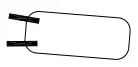 | SP-ST | A* | Closes |
| -36 | 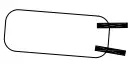 | SP-ST | A* | Opens |
| -54 |  | DP-ST | B | Opens |
| -103 |  | DP-ST | A | Closes |
| -113 | 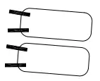 | DP-ST | A* | Closes |
| -127 | 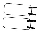 | DP-ST | A | Opens |
| -152 |  | SP-DT | B | One Closes as Other Opens |
| -153 |  | SP-DT | B | One Closes as Other Opens |
| -154 | 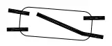 | 2 Circuits 1 Circuit | B | Close Opens |
| -155 | 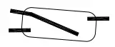 | 1 Circuit 2 Circuit | B | Closes Open |
| -156 |  | SP-DT | A | One Closes as Other Opens |
| -705 |  | SP-DT SP-DT | B A | One Closes as Other Opens Opens |
| -729 |  | SP-ST SP-DT | B A | One Closes as Other Opens Opens |
| -804 |  | DP-DT | B | Two Close Two Open |
| -815 |  | B | 4P-ST Close (2) 9-67 | |
| -816 |  | B | 4P-ST Open (2) 9-67 | |
| *Consult factory. | ||||
| ELECTRICAL RATING CHART | ||||||||
| Code | Circuit Suffix | AC Capacity | DC Capacity | Horsepower | ||||
| 120 V | 240 V | 440 V | 120 V | 240 V | AC | DC | ||
| A B C | -2, -3 -153 -2, -3 -2, -3 | 10A 4A 5A 0.3A | 5A 2A 2A 0.15A | 3A 1* NA NA | 10A 4A 2-1/2A 0.15A | 5A 2A 1A 0.07A | 3/4 1/8 1/8 NA | 1/3 NA 1/10 NA |
| *Consult factory. | ||||||||
Explosion-proof prefixed by DAH, DAHF DRH, DSH, DSHF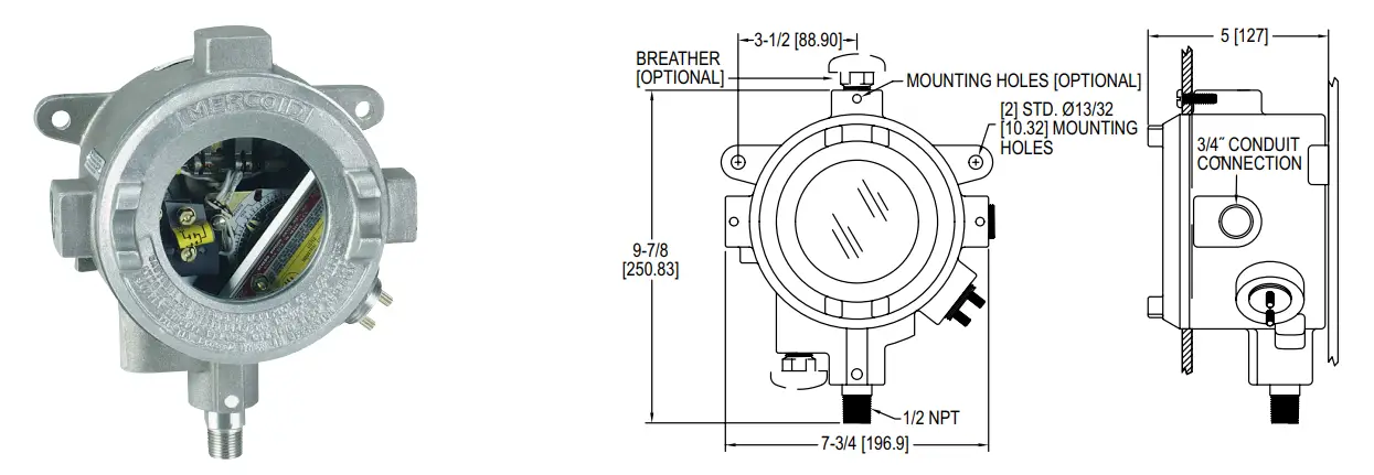
Watertight NEMA 2, 3, 4 – Prefixed by DAW, DRW, DSW, DLW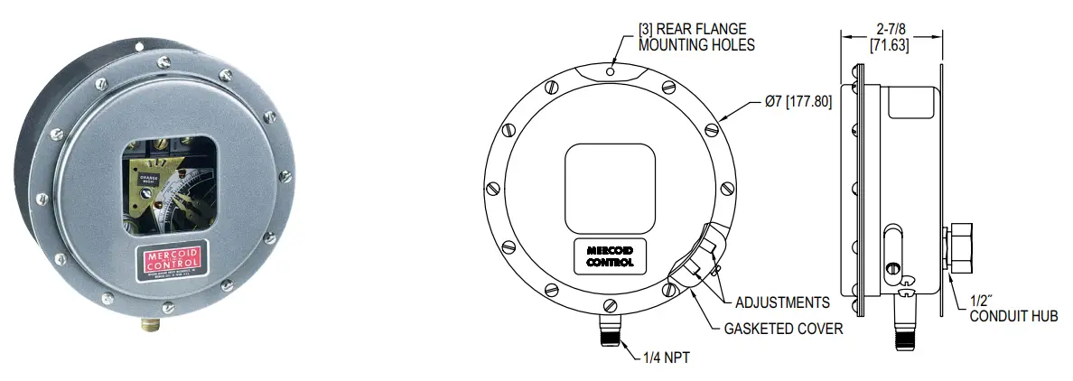
Explosion-proof prefixed by DAE, DLE, DRE, DSE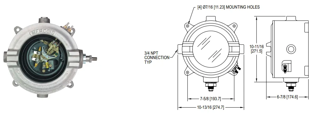
©Copyright 2022 Dwyer Instruments, Inc.
Printed in U.S.A. 3/22
FR# 441852-00 Rev. 5
DWYER INSTRUMENTS, INC.
P.O. BOX 373 • MICHIGAN CITY, INDIANA 46360, U.S.A.
Phone: 219-879-8000
Fax: 219-872-9057
www.dwyer-inst.com
e-mail: [email protected]