FS S5810 Series Managed L2/L3 Enterprise Switches User Guide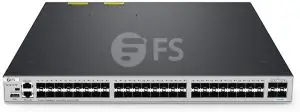
Introduction
Thank you for choosing S5810 Series Switches. This guide is designed to familiarize you with the layout of the switch and describes how to deploy the switch in your network.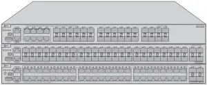
- S5810-28FS
- S5810-48FS
- S5810-48TS-P
Accessories
- Power Cord x2

- Mini Console Cable x1

- Grounding Cable x1

- Rubber Pad x4

- Mounting Bracket x2

- M4 Screw x8


![]() NOTE: S5810 series switches have dust plugs delivered with them. Keep the dust plugs properly and use them to protect idle optical ports.
NOTE: S5810 series switches have dust plugs delivered with them. Keep the dust plugs properly and use them to protect idle optical ports.
Hardware Overview
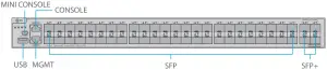
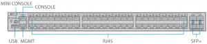
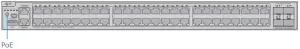
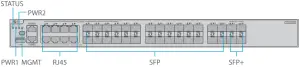
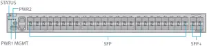
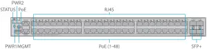
Front Panel Ports
- S5810-28FS

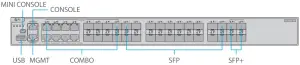
- S5810-48FS
- S5810-48TS-P
Ports Description
RJ45 10/100/1000BASE-T ports for Ethernet connection COMBO One RJ45 port and one SFP slot, with one port active at a time SFP SFP ports for 100M/1G connection SFP+ SFP+ ports for 1/10G connection MGMT An out-of-band Ethernet management port MINI CONSOLE A serial port for installing the software driver Ports Description
CONSOLE An RJ45 console port for serial management USB
A USB management port for software and configuration backup and offline software upgrade
Front Panel Button
- S5810-48TS-P

Button
Description
PoE Switch the display mode between PoE mode and switch mode.
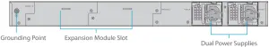
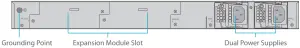
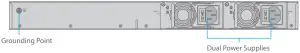
Back Panels
- S5810-28FS

- S5810-48FS

- S5810-48TS-P
Front Panel LEDs
- S5810-28FS

- S5810-48FS
- S5810-48TS-P

LEDs
Status
Description
STATUS
Off
The system is powered off. Blinking Green (3Hz)
The switch is being initialized with 3Hz blinking. Continuous blinking indicates errors. Blinking Green (10Hz)
Supports remote on/off to locate the switch. Solid Green
The switch is operational. Solid Yellow
Temperature warning, check the working environment of the switch immediately. Solid Red
Switch is faulty. PWR1/PWR2
Off
The power module is not in place or not receiving power. Solid Green
The power module is connected and able to work. Solid Red
The redundant power is faulty or the AC power cord is not connected. MGMT
Off
The port is not connected. Solid Green
The port is connected at 1000 Mbps. Blinking Green
The port is receiving or transmitting traffic at 1000 Mbps. Solid Yellow
The port is connected at 10/100 Mbps. Blinking Yellow
The port is receiving or transmitting traffic at 10/100 Mbps. PoE
Solid Green
Indicates the switching state. Solid Yellow
Indicates the PoE state. RJ45
Off
The port is not connected. Solid Green
The port is connected at 1000 Mbps. Blinking Green
The port is receiving or transmitting traffic at 1000 Mbps. Solid Yellow
The port is connected at 10/100 Mbps. Blinking Yellow
The port is receiving or transmitting traffic at 10/100 Mbps. LEDs
Status
Description
PoE (1-48)
Off PoE is not enabled. Solid Green PoE is enabled. The port is operational. Solid Yellow The port has a PoE fault of overload. SFP
Off The port is not connected. Solid Green The port is connected at 1000 Mbps. Blinking Green The port is receiving or transmitting traffic at 1000 Mbps. Solid Yellow The port is connected at 100 Mbps. Blinking Yellow The port is receiving or transmitting traffic at 100 Mbps. SFP+
Off The port is not connected. Solid Green The port is connected at 1/10 Gbps. Blinking Green The port is receiving or transmitting traffic at 1/10 Gbps.
Installation Requirements
Before you begin the installation, make sure that you have the followings:
- Phillips screwdriver.
- Standard-sized, 19″ wide rack with a minimum of 1U height available.
- Category 5e or higher RJ-45 Ethernet cables, ber optical cables and console cable for connecting network devices.
Site Environment:
- Do not operate it in an area that exceeds an ambient temperature of 50°C.
- Do not install the equipment in a dusty environment.
- The installation site must be free from leaking or dripping water, heavy dew, and humidity.
- The installation site must be well ventilated. Ensure that there is adequate airflow around the switch.
- The switch should be installed at least 1U (44.45mm) away from devices to its sides.
- Be sure that the switch is level and stable to avoid any hazardous conditions.
- Ensure rack and working platforms are well earthed.
Mounting the Switch
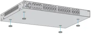
Desk Mounting

- Attach four rubber pads to the bottom.
- Place the chassis on a desk.
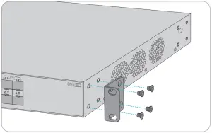
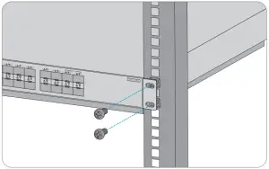
Rack Mounting
- Secure the mounting brackets to the two sides of the switch with eight M4 screws.

- Attach the switch to the rack using four M6 screws and cage nuts.
- Secure the mounting brackets to the two sides of the switch with eight M4 screws.
Installing the Power Supply Module
- Take a new power module out of the package and confirm the input mode and the input parameters of the power module match the requirements.
- Remove the old power module and take the plane printed with power information as the top panel of the power module. Hold the handle of the power module with one hand, and hold the end of the power module with the other hand. Insert it into the chassis along the guide rail uprightly and slowly until it clicks into place, and make sure that it is in good contact with the power slot.
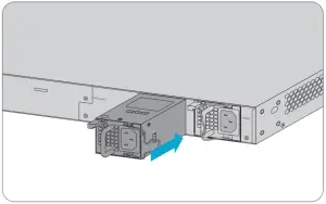
![]() NOTE: Insert the power module steadily. Please pay attention to the direction of the power panel to avoid wrong insertion. If the position is not proper, press the plug of the power module and hold on to the module handle with one hand to pull it out slowly, then re-insert it.
NOTE: Insert the power module steadily. Please pay attention to the direction of the power panel to avoid wrong insertion. If the position is not proper, press the plug of the power module and hold on to the module handle with one hand to pull it out slowly, then re-insert it.
Grounding the Switch
- Connect one end of the grounding cable to a proper earth ground, such as the rack in which the switch is mounted.
- Secure the grounding lug to the grounding point on the switch back panel with the washers and screws.
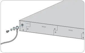
![]() CAUTION: The earth connection must not be removed unless all supply connections have been disconnected.
CAUTION: The earth connection must not be removed unless all supply connections have been disconnected.
Connecting the Power
- Plug the AC power cord into the power port on the back of the switch.
- Connect the other end of the power cord to an AC power source.
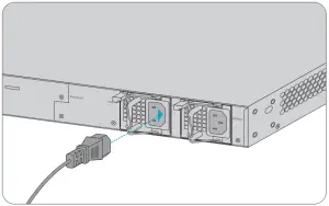
![]() WARNING: Do not install power cable while the power is on.
WARNING: Do not install power cable while the power is on.
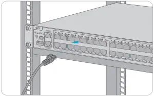
Connecting the RJ45 Ports
- Connect an Ethernet cable to the RJ45 port of IP cameras, IP telephone, Access Points (AP), or other network devices.
- Connect the other end of the Ethernet cable to the RJ45 port of the switch.
Connecting the SFP/SFP+ Ports
- Plug the compatible SFP/SFP+ transceiver into the SFP/SFP+ port.
- Connect a fiber optic cable to the fiber transceiver. Then connect the other end of the cable to another fiber device.
![]() WARNING: Laser beams will cause eye damage. Do not look into bores of optical modules or optical fibers without eye protection.
WARNING: Laser beams will cause eye damage. Do not look into bores of optical modules or optical fibers without eye protection.
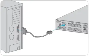
Connecting the Console Port
- Insert the RJ45 connector into the RJ45 console port on the front of the switch.
- Connect the DB9 female connector of the console cable to the serial port on the computer.
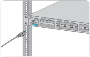
Connecting the MGMT Port
- Connect one end of a standard RJ45 Ethernet cable to a computer.
- Connect the other end of the cable to the MGMT port on the front of the switch.
Stacking the Switches
The S5810 series switches support stacking up to 8 switches between the same series together.
The switch can be physically stacked using optical ber cables connected to SFP/SFP+ transceivers or 1G/10G Direct Attach Cables (DAC). Only four SFP+ uplinks on the switch can be used for physical stacking.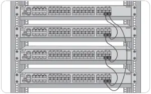
Configuring the Switch
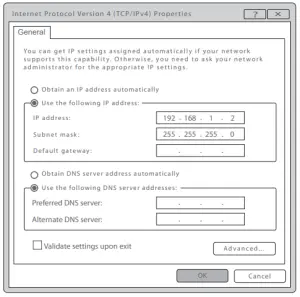
Configuring the Switch Using the Web-based Interface
- Step 1: Connect the computer to the Management port of the switch using the network cable.
- Step 2: Set the IP address of the computer to 192.168.1.x.(“x” is any number from 2 to 254.)

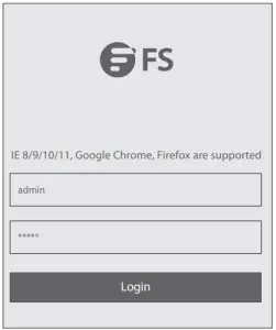
- Step 3: Open a browser, type http://192.168.1.1, and enter the default username and password, admin/admin.

- Step 4: Click Login to display the web-based configuration page.
Configuring the Switch Using the Console Port
- Step 1: Connect a computer to the switch’s console port using the console cable.
- Step 2: Start the terminal simulation software such as HyperTerminal on the computer.
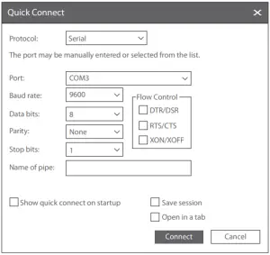
- Step 3: Set the parameters of the HyperTerminal: 9600 bits per second, 8 data bits, no parity, 1 stop bit and no flow control.

- Step 4: After setting the parameters, click Connect to enter.
Troubleshooting
Power System Fault
The indicator on the front panel of host is OFF. The Status indicator of fan module is OFF, and the fan does not work. The indicator on the panel of the power module is OFF and the fan does not work.
Please check the following:
First, disconnect the power cord of the power module.
- Whether the cables of the cabinet have been correctly connected.
- Whether the cabinet power sockets are loosely connected to power modules.
- Whether the power modules are installed correctly.
Connecting the Switch Remotely Unsuccessfully
- Test network connectivity through ping.
- If the network is reachable, try restarting the switch.
- Check if the corresponding service is enabled.
The Port is not Working, the LED Indicator is Off
- Ensure the switch ports are in the no shutdown state.
- Check if the switch can read the DDM information.
- Check if the port speed setting is correct.
- Try looping the switch cable.
Troubleshooting for Terminal No-show
After power-on, if the configuration terminal shows nothing, you can firstly check the following:
- Whether serial port cables are connected correctly.
- Whether the configuration of the serial port on the HyperTerminal.
Troubleshooting for Terminal Show Error Codes
If the configuration terminal shows error codes, it is likely that the terminal (such as HyperTerminal) parameters are set incorrectly. Please confirm the parameters of the terminal (such as HyperTerminal).
Support and Other Resources
- Download: https://www.fs.com/download.html
- Help Center: https://www.fs.com/service/help_center.html
- Contact Us: https://www.fs.com/contact_us.html
Product Warranty
FS ensures our customers that any damage or faulty items due to our workmanship, we will offer a free return within 30 Days from the day you receive your goods. This excludes any custom made items or tailored solutions.

Warranty: S5810 series switches enjoy 5 years limited warranty against defect in materials or workmanship. For more details about warranty, please check at https://www.fs.com/policies/warranty.html
Return: If you want to return item(s), information on how to return can be found at https://www.fs.com/policies/day_return_policy.html