![]() 800 Series Dilution-At-Hand Extreme Chemical Dispenser
800 Series Dilution-At-Hand Extreme Chemical Dispenser
Instructions 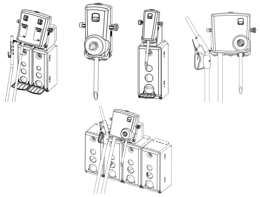 DEMA® DILUTION-AT-HAND EXTREME
800 Series Chemical Dispensers
Overview
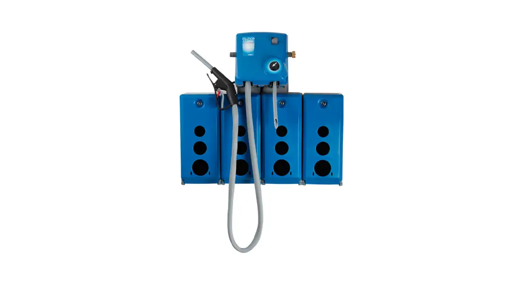
The DILUTION-AT-HAND EXTREME chemical dispenser series combines the proven technology of the DEMA® DILUTION-AT-HAND with a new look and modular chemical enclosures.
The dispenser series accurately dilutes chemical concentrates with water and dispenses the diluted mixture at either a high flow rate to fill buckets and scrubbers or a low flow rate to fill bottles and small containers.
Each dispenser can be set up to meet specific application needs with the ability to offer:
- High and low flow dispensing
- 2 Liter or 1 Gallon (5 Liter) chemical cabinets
- Selector valve option to dispense more than one chemical per dispensing unit
- Bottle filling or bucket filling
- Option of a remote gun for bucket or scrubber filling
- Dilution ratios up to 3:1 for low flow dispensing and up to 7:1 for high flow dispensing
- Supplied metering tips allow for leaner ratios of dilution
Warnings
![]() All installations must conform to local plumbing codes and use approved backflow prevention devices. A pressure indicating tee is to be installed with existing faucets according to local plumbing codes in the state of Wisconsin and any other state that requires the use of a pressure indicting tee.
All installations must conform to local plumbing codes and use approved backflow prevention devices. A pressure indicating tee is to be installed with existing faucets according to local plumbing codes in the state of Wisconsin and any other state that requires the use of a pressure indicting tee. ALWAYS WEAR PROTECTIVE CLOTHING AND EYEWEAR WHEN WORKING WITH CHEMICAL PRODUCTS.
Packing List
|
Part Number |
Description | 801 | 801GAP-S2L | 803GAP | 803GAP-Q2L | 802GAPRF | 804 | 820 | 830 | 822 | 830 | 830 | 820 | 822 | |
| L1107 | CHEMICAL LABELS | 1 | 1 | 1 | 1 | 1 | 1 | 1 | 1 | 1 | 1 | 1 | 1 | 1 | |
| 100-15K | METERING TIP KIT | 1 | 1 | 1 | 1 | 1 | 1 | 1 | 1 | 1 | 1 | 1 | 1 | 1 | |
| 61-107-2 | SMALL CERAMIC WEIGHT | 1 | 1 | 4 | 4 | 1 | 4 | 2 | 5 | 2 | 5 | 5 | 2 | 2 | |
| 98-42-2 98-43-1 | TUBE (GAP) TUBE (AG) | 1 | 1 | 1 | 1 | 2 | 1 | 1 | 1 | 1 | 2 | 1 |  | ||
| 100-16E-1 | TUBING & FOOT VALVE 1/4″ X 8′ | 1 | 4 | 1 | 4 | 2 | 5 | 2 | 5 | 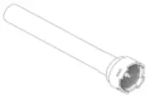 | |||||
| 100-16E-3 | TUBING & FOOT VALVE 1/4″ X 32″ | 1 | 4 | 5 | 2 | 2 | 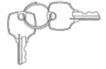 | ||||||||
| 66-21K | KEY SET | 1 | 1 | 1 | 1 | 1 | 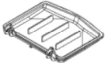 | ||||||||
| 89-10-1 | DRIP TRAY | 1 | 1 | 1 | 2 | 1 | 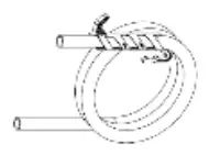 | ||||||||
| 89-30-GAP 89-30-G | BUCKET TUBE 6’ | 1 | 1 | 1 | 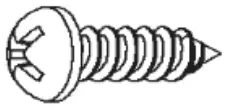 | ||||||||||
| 66-53-4 | MOUNTING SCREW | 2 | 2 | 2 | 8 | 2 | 2 | 4 | 4 | 4 | 4 | 8 | 4 | 2 |  |
| 66-52 | WALL ANCHOR | 2 | 2 | 2 | 8 | 2 | 2 | 4 | 4 | 4 | 4 | 8 | 4 | 2 | m |
Operational Requirements
Water Supply Requirements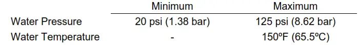
** Recommended water pressure is between 20 psi (1.38 bar) and 80 psi. (5.52 bar). If pressure exceeds 80 psi, it is recommended that a 66.43 regulator is used.
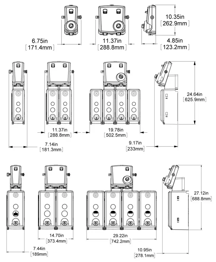
Overall Size
Installation
Mounting
Dispenser Only
- “Remove selector knobs (if installed).” Selector knob is removed by first rotating the locking cam 90 degrees. Locking cam is unlocked when slot is perpendicular to selector arrow. Once unlocked, pull knob from selector body to remove.” Remove the dispenser cover by depressing the tab on the top of the cover.
- Position the dispenser on the wall and mark the screw locations.
- Chemical containers can be no greater than 6’ (1.83 meters) below the dispenser.
- Install the supplied anchors in the wall.
- Mount the dispenser to the wall with the supplied screws.
- Replace the cover and any selector knob(s).
Dispenser with Chemical Cabinets
1. Open the door(s) of the chemical cabinet(s) using the supplied key.
2. Position the dispenser on the wall and mark the screw locations.
3. Install the supplied anchors in the wall. Use two anchors and two screws for
each chemical cabinet.
4. Mount the dispenser to the wall with the supplied screws.
Metering Tips & Chemical Supply Tubes
- Each dispenser is supplied with at least one metering tip kit. Chose the appropriate color metering tip based on the supplied chemical induction chart.
- Remove any selector knobs (if installed) by pulling on the knobs.
- Remove the dispenser head by depressing the tab on the top of the cover.
- Screw the metering tip into the chemical barb on the dispenser head.
- Cut to length the chemical supply tube to remove excess tubing.
- Install a supplied ceramic weight onto the tube.
- Push the tubing onto the proportioner barb.
- Replace the cover and any selector knobs
- Place the ceramic weight, tubing, and foot valve into the chemical.
Water Supply
1. Attach a garden hose to the water inlet of the unit.
Metering Tip & Action Gap Proportioner Table
Table 1: “Action Gap”/Proportioner
Induction Flow Rates w/Standard 1/4″ Barb & Tubing
| Metering Tip Color | (1 GPM Flow Rate Action Gap Proportioner)Injection Rates For Viscosities Shown | (4 GPM Flow Rate Action Gap Proportioner) Injection Rates For Viscosities Shown | ||||||||||
| 1 cps | 75 cps | 200 cps | 1 cps | 75 cps | 200 cps | |||||||
| Oz/Gal | Ratio | Oz/Ga l | Ratio | Oz/Ga l | Ratio | Oz/Ga l | Ratio | Oz/Gal | Ratio | Oz/Gal | Ratio | |
| Tan | 1.03 | 125-1 | 0.76 | 168-1 | 0.38 | 333-1 | 0.33 | 387-1 | 0.26 | 500-1 | 0.12 | 1090-1 |
| Orange | 1.24 | 103-1 | 0.98 | 130-1 | 0.53 | 241-1 | 0.42 | 307-1 | 0.32 | 430-1 | 0.17 | 735-1 |
| Turquoise | 1.43 | 89-1 | 1.07 | 119-1 | 0.61 | 211-1 | 0.51 | 251-1 | 0.34 | 382-1 | 0.19 | 676-1 |
| Pink | 2.47 | 52-1 | 1.58 | 81-1 | 0.92 | 139-1 | 0.78 | 165-1 | 0.56 | 230-1 | 0.3 | 422-1 |
| Light Blue | 3.05 | 42-1 | 2.1 | 61-1 | 1.06 | 121-1 | 0.87 | 147-1 | 0.67 | 192-1 | 0.33 | 391-1 |
| Brown | 3.48 | 37-1 | 2.31 | 55-1 | 1.15 | 111-1 | 0.99 | 129-1 | 0.74 | 174-1 | 0.37 | 345-1 |
| Red | 4.38 | 29-1 | 2.83 | 45-1 | 1.23 | 104-1 | 1.37 | 93-1 | 0.91 | 141-1 | 0.44 | 289-1 |
| White | 5.33 | 24-1 | 3.1 | 42-1 | 1.37 | 93-1 | 1.52 | 84-1 | 1.04 | 123-1 | 0.48 | 264-1 |
| Green | 6.38 | 20-1 | 3.63 | 35-1 | 1.4 | 91-1 | 1.72 | 74-1 | 1.22 | 105-1 | 0.52 | 244-1 |
| Blue | 6.77 | 19-1 | 3.78 | 34-1 | 1.45 | 88-1 | 2.13 | 60-1 | 1.27 | 101-1 | 0.54 | 239-1 |
| Yellow | 9.90 | 13-1 | 5.1 | 25-1 | 1.48 | 86-1 | 3.05 | 42-1 | 1.71 | 75-1 | 0.56 | 229-1 |
| Black | 15.00 | 9-1 | 6.54 | 20-1 | 1.53 | 84-1 | 4.50 | 28-1 | 1.96 | 65-1 | 0.57 | 224-1 |
| Purple | 24.94 | 5-1 | 7.28 | 18-1 | 1.57 | 82-1 | 7.75 | 17-1 | 2.4 | 53-1 | 0.59 | 217-1 |
| Gray | 35.94 | 4-1 | 8.5 | 15-1 | 1.64 | 78-1 | 9.86 | 13-1 | 2.54 | 50-1 | 0.63 | 204-1 |
| No Tip | 42.2 | 2-1 | 9.35 | 14-1 | 1.87 | 69-1 | 19.63 | 7-1 | 3.16 | 40-1 | 0.67 | 190-1 |
Note: All induction flow rates are based on a water pressure of 40 psi.
Leaner dilutions can be achieved by ordering DEMA® ultra lean metering tip kit 100-15KU.
Service Note: Standard size ¼” hose barbs and metering tips that come with this model are used for water thin (1cps) products. Ratios as low as parts-per-million, can be achieved with the use of a capillary metering tip. More viscous products (75cps – 200cps) may require larger 3/8” hose barbs and metering tips. If you are having difficulty achieving the ratio you require, call DEMA® technical service.
Metering Tip & Air Gap Proportioner Table
Table 2: “Air Gap” Proportioner
Induction Flow Rates w/Standard 1/4″ Barb and Tubing
| Metering Tip Color | 164 BAG (1 GPM Flow Rate Air Gap Proportioner) Injection Rates For Viscosities Shown | 163 BAG (4 GPM Flow Rate Air Gap Proportioner) Injection Rates For Viscosities Shown | ||||||||||
| 1 cps | 75 cps | 200 cps | 1 cps | 75 cps | 200 cps | |||||||
| Oz/Gal | Ratio | Oz/Ga l | Ratio | Oz/Ga l | Ratio | Oz/Ga l | Ratio | Oz/Gal | Ratio | Oz/Gal | Ratio | |
| Tan | 1.25 | 102-1 | 0.90 | 142-1 | 0.60 | 213-1 | 0.30 | 427-1 | 0.20 | 640-1 | 0.15 | 853-1 |
| Orange | 1.70 | 75-1 | 1.20 | 107-1 | 0.80 | 160-1 | 0.40 | 320-1 | 0.30 | 427-1 | 0.25 | 512-1 |
| Turquoise | 2.15 | 60-1 | 1.55 | 83-1 | 1.10 | 116-1 | 0.60 | 213-1 | 0.40 | 320-1 | 0.30 | 427-1 |
| Pink | 3.00 | 43-1 | 2.00 | 64-1 | 1.50 | 85-1 | 0.80 | 160-1 | 0.50 | 256-1 | 0.40 | 320-1 |
| Light Blue | 3.90 | 33-1 | 2.75 | 47-1 | 1.80 | 71-1 | 1.00 | 128-1 | 0.70 | 183-1 | 0.45 | 284-1 |
| Brown | 4.55 | 28-1 | 3.00 | 43-1 | 2.00 | 64-1 | 1.20 | 107-1 | 0.80 | 160-1 | 0.50 | 256-1 |
| Red | 5.80 | 22-1 | 3.60 | 36-1 | 2.30 | 56-1 | 1.50 | 85-1 | 0.90 | 142-1 | 0.60 | 213-1 |
| White | 7.00 | 18-1 | 4.45 | 29-1 | 2.70 | 47-1 | 1.85 | 69-1 | 1.10 | 116-1 | 0.70 | 183-1 |
| Green | 7.90 | 16-1 | 5.00 | 26-1 | 3.00 | 43-1 | 2.00 | 64-1 | 1.25 | 102-1 | 0.80 | 160-1 |
| Blue | 9.80 | 13-1 | 5.75 | 22-1 | 3.30 | 39-1 | 2.50 | 51-1 | 1.50 | 85-1 | 0.82 | 156-1 |
| Yellow | 14.80 | 9-1 | 7.35 | 17-1 | 3.55 | 36-1 | 4.00 | 32-1 | 1.85 | 69-1 | 0.90 | 142-1 |
| Black | 20.15 | 6-1 | 8.50 | 15-1 | 3.70 | 35-1 | 5.50 | 23-1 | 2.00 | 64-1 | 0.94 | 136-1 |
| Purple | 27.80 | 5-1 | 9.80 | 13-1 | 3.80 | 34-1 | 8.80 | 15-1 | 2.40 | 53-1 | 0.96 | 133-1 |
| Gray | 31.60 | 4-1 | 10.50 | 12-1 | 3.90 | 33-1 | 11.65 | 11-1 | 2.50 | 51-1 | 1.00 | 128-1 |
| No Tip | 35.70 | 3.6-1 | 11.80 | 11-1 | 4.50 | 28-1 | 16.20 | 8-1 | 3.00 | 43-1 | 1.20 | 107-1 |
Note: All induction flow rates are based on a water pressure of 40 psi.
Leaner dilutions can be achieved by ordering DEMA® ultra lean metering tip kit 100-15KU.
Service Note: Standard size ¼” hose barbs and metering tips that come with this model are used for water thin (1cps) products. Ratios as low as parts-per-million, can be achieved with the use of a capillary metering tip. More viscous products (75cps – 200cps) may require larger 3/8” hose barbs and metering tips. If you are having difficulty achieving the ratio you require, call DEMA® technical service.
Operation
Dispensing of diluted chemical can be performed in several waysdepending on the dispenser.
- Lever / Button Activation – The unit can be operated by pushing up on the lever. This lever can be locked in an “On” position by depressing the lever inward. To unlock
the “On” position, either depress the lever or push up on the bottle fill lever.
- Bottle Fill Activation – Slide a bottle up to the bottom of the unit and push up on the shown lever.

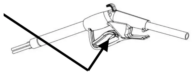
- Remote Fill Activation – Depress the trigger on the handle of the remote gun. The remote gun can be locked “On” by rotating the red lever downward. To disengage this
lever, depress the trigger.

Troubleshooting
(Some models may not include all items listed below)
| Symptom | Probable Cause | Remedy |
| Proportioner fails to draw chemical properly. | 1. Insufficient water supply pressure. 2. Foot valve has dirt/chemical build- up. 3. Proportioner metering tip clogged with dried chemical. 4. Mineral deposits are located on Air Gap nozzle. 5. Bucket fill (4 GPM) side appears to have slow flowing water stream. | 1. 20 PSI is the minimum allowable pressure. Seek Plumber if necessary to increase water pressure. 2. Soak in hot water to clean. 3. Soak in hot water to clean interior passages. 4. Soak nozzle and inlet screen in hot water or product such as CLR to clean mineral deposits. 5. Flow disc assembly must be removed from lower section of water valve assembly if installed. |
| “Air Gap” Proportioner is dripping or spraying a mist (fan pattern) of water. | 1. Mineral deposits are located on Air Gap nozzle. | 1. Soak nozzle and inlet screen in hot water or off the shelf product such as CLR to clean and remove mineral deposits. |
| Water valve is not shutting off completely. | 1. “Sliding lever” return spring may be missing. 2. “Sliding lever” is not returning all the way down due to interference between the sliding lever and either the chemical supply and/or outlet tubing. 3. Bucket fill outlet hose is catching the bottom edge of the sliding lever during normal usage. | 1. Remove cover and visually check for sliding lever return spring. Replace if missing. 2. Remove cover and visually check for any tubes rubbing the sliding lever. Routing of chemical supply and outlet tubing must not restrict the movement of the sliding lever. Reroute tubing. 3. Don’t pull the bucket fill outlet hose too tight from either side otherwise sliding lever may not return properly. |
| Water valve is leaking. | 1. Enclosing tube nut is too loose. 2. One or more of the valve o-ring connections are out-of-position. Identify each leak before disassembly. | 1. Shut water supply off first. Hand-tighten the enclosing Hose nut. Do not overtighten w/tool. 2. “O-ring” seals may be pushed out of place or missing when sub-assembling valve together. |
| Threaded connections are leaking water. | 1. The connection between the blend center and water supply line is too loose or rubber washer is missing. 2. Backflow prevention devices and/or proportioners are too loose. | 1. Shut water supply off first. Carefully tighten the female hose coupling on the blend center to the inlet water supply line. Do not overtighten. 2. Tighten loose connection(s) with tools if necessary. Do not overtighten if using tools. |
| Proportioner continues to draw chemical after water valve is closed. | 1. Concentrated chemical is positioned higher than the proportioner. | 1. Move the concentrated chemical so it is lower than the proportioner. |
Parts List
BOTTLE/HOSE FILL APPLICATIONS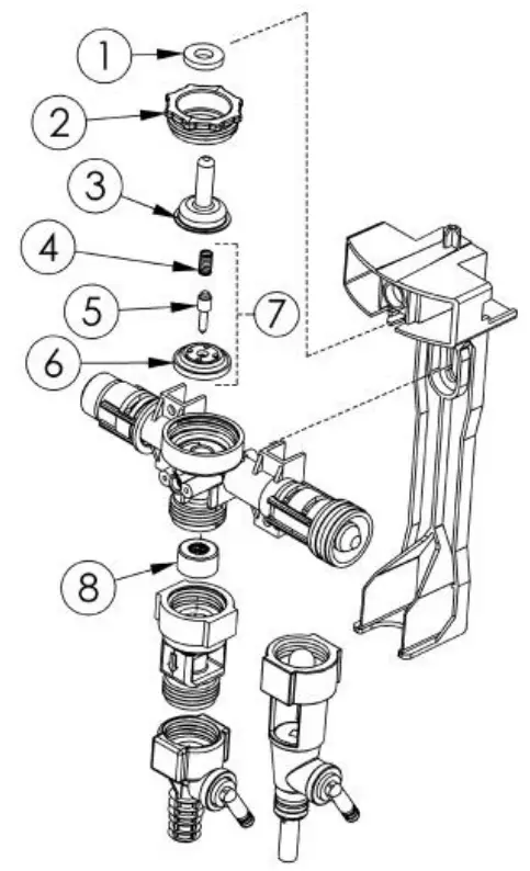
| NO. | PART NO. | DESCRIPTION |
| 1 | 63-35 | Magnet |
| 2 | 98-7-2 | Enclosing Tube Nut |
| 3 | 41-7-25 | Enclosing Tube |
| 4 | 98-41-1 | Spring |
| 5 | 98-24-1 | Plunger |
| 6 | 41-15-10 | Diaphragm With Center Hole EPDM |
| 7 | 98-25-1 | Bottle/Hose Repair Kit |
| 8 | 89-20-1 | Flow Disc Assembly (1 GPM only) |
REMOTE FILL APPLICATION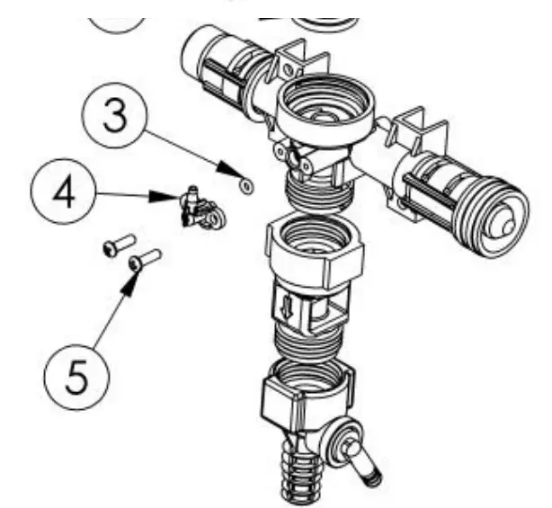
| NO. | PART NO. | DESCRIPTION |
| 1 | 98-5-2 | Nut, Diaphragm |
| 2 | 98-26-1 | Diaphragm Without Center Hole EPDM |
| 3 | 26-35 | O-ring (EPDM) |
| 4 | 98-15-1 | Elbow |
| 5 | 58-60 | #6 Hi Lo Screw ½” Lg. (2 Required) |
REMOTE FILL APPLICATION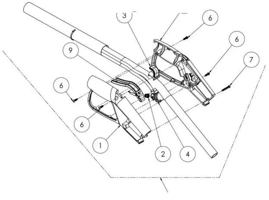
| NO. | PART NO. | DESCRIPTION |
| 1 | 40-731-1 | Remote Gun Fill Half (R.H.) |
| 2 | 40-737-1 | Trigger Return Spring |
| 3 | 40-734-1 | Hook |
| 4 | 40-775-1 | Valve Assembly |
| 5 | 40-730-1 | Remote Gun Fill Half (L.H.) |
| 6 | 58-60 | #6 Hi Lo Screw ½” Lg. (4 Required) |
| 7 | 21-009-6 | #6 Hi Lo Screw 1” Lg. (1 Required) |
| 8 | 40-736-1 | Remote Fill Assembly |
| 9 | 40-735-1 | Activation Lever ASM |
BACK FLOW & PROPORTIONING DEVICES 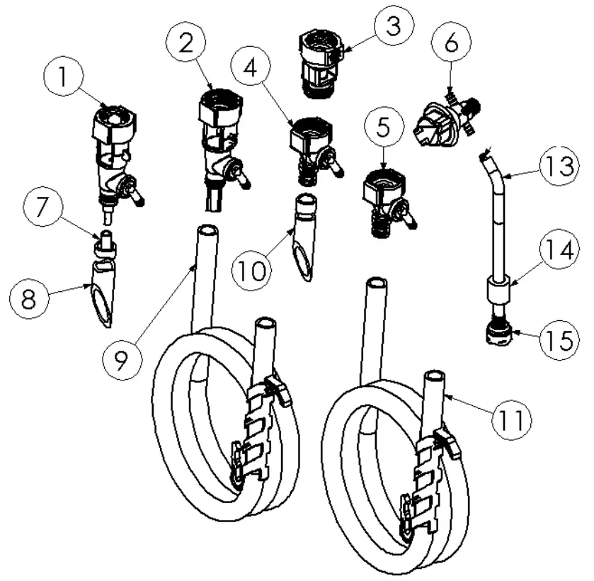
| NO. | PART NO. | DESCRIPTION |
| 1 | 61-32AGP | Proportioner Assembly (1 GPM) |
| 2 | 61-22-3GAP-2 | Proportioner Assembly (4 GPM) |
| 3 | 16-30 | Action Gap Assembly |
| 4 | 61-99-2 | Proportioner Assembly (1 GPM) |
| 5 | 61-22-3 | Proportioner Assembly (4 GPM) |
| 6 | 63-53-13 | Selector and Knob Assembly |
| 7 | 63-82 | Tube, 3/16” I.D. Outlet |
| 8 | 98-43-1 | Tube, 9/16” I.D. Outlet |
| 9 | 98-30-AG | Outlet 9/16″ I.D. Hose W/Hanger (6′ LG) |
| 10 | 98-42-2 | Tube, 1/2” I.D. Outlet |
| 11 | 89-30-GAP | Outlet 1/2″ I.D. Hose W/Hanger (6′ LG) |
| 13 | 100-12 /100- 12E | Hose, 7/32” I.D. x 8’ Lg./7/32” I.D. x 50’ Lg. |
| 14 | 61-107-2 | Ceramic Weight, 3/8” I.D. |
| 15 | 100-16E | Foot Valve Assembly (EPDM) |
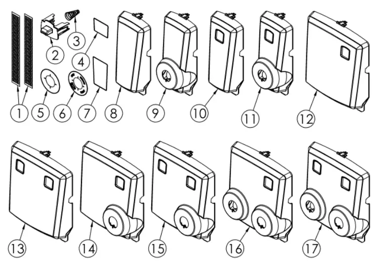
LABELS, LIFT BUTTON AND COVERS
| NO. | PART NO. | DESCRIPTION | NO. | PART NO. | DESCRIPTION |
| 1 | L1107 | Chemical Label | 10 | 89-2-3 | Cover, Single (Lift Button) |
| 2 | 89-5-1 | Lift Button | 11 | 89-2-4 | Cover, Single (Lift Button & Selector) |
| 3 | 63-36 | Lift Button Return Spring | 12 | 89-4-1 | Cover, Dual (RH Lift Button) |
| 4 | L1074 | DEMA® Label, Small | 13 | 89-4-2 | Cover, Dual (LH & RH Lift Buttons) |
| 5 | L1075 | Selector label, Blank | 14 | 89-4-3 | Cover, Dual (RH Lift Button & RH Selector) |
| 6 | L1108 | Selector label, 4-Dilution | 15 | 89-4-4 | Cover, Dual (Both Lift Buttons & RH Selectors) |
| 7 | L1073 | DEMA® Label, Large | 16 | 89-4-5 | Cover, Dual (RH Lift Buttons & Both Selectors) |
| 8 | 89-2-1 | Cover, Single (Plain) | 17 | 89-4-6 | Cover, Dual (Both Lift Buttons & Both Selectors) |
| 9 | 89-2-2 | Cover, Single (Selector) | |||
2 LITER AND 1 GALLON (5 LITER) STORAGE BOX ASSEMBLIES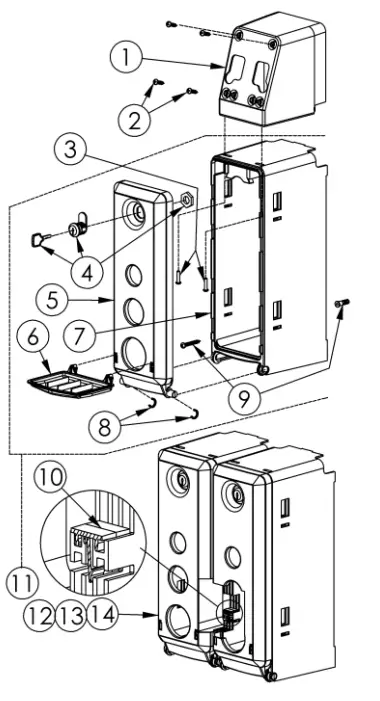
| NO. | 2 LITER PART NO. | 1GALLON PART NO. | DESCRIPTION |
| 1 | 89-11-1 | 89-11-1 | Mounting Support (1for Single & 2 for Dual Unit) |
| 2 | 44-116-5 | 44-116-5 | #8 Hi-Lo Screws (4 Per Dispenser Unit) |
| 3 | 44-116-1 | 44-116-5 | #8 Hi-Lo Screws (2 per Mounting Support) |
| 4 | 81-69 | 81-69 | Cabinet Lock with Key / Key Only (66-21K) |
| 5 | 89-8-1 | 89-9-1 | Storage Box Door |
| 6 | 89-10-1 | 89-10-1 | Drip Tray |
| 7 | 89-6-1 | 89-7-1 | Storage Box Base |
| 8 | 89-19-1 | 89-19-1 | Door Retaining Clip (2 per Box Assy.) |
| 9 | 98-40-1 | 98-40-1 | #10 Screw & Anchor Set (Qty. 2 /Set) |
| 10 | 89-12-1 | 89-12-1 | Box Retaining Clip (2 for 2 Boxes +2 per Box) |
| 11 | 89-16-1 | 89-17-1 | Single Box Assy. Kit (1 Drip Tray & Mtg. Hardware) |
| 12 | 89-16-2 | 89-17-2 | Dual Box Assy. Kit (1 Drip Tray & Mtg. Hardware) |
| 13 | 89-16-3 | 89-17-3 | Triple Box Assy. Kit (1 Drip Tray & Mtg. Hardware) |
| 14 | 89-16-4 | 89-17-4 | Quad Box Assy. Kit (1 Drip Tray & Mtg. Hardware) |
Warranty
Merchandise Returns
No merchandise will be returned for credit without DEMA®’s written permission. Returned merchandise authorization number is required in advance of return.
Product Warranty
DEMA® products are warranted against defective material and workmanship under normal use and service for one year from the date of manufacture. This limited warranty does not apply to any products that have a normal life shorter than one year or failure and damage caused by chemicals, corrosion, physical abuse, or misapplication. Rubber and synthetic rubber parts such as “O”-rings, diaphragms, PVC tubing, and gaskets are considered expendable and are not covered under warranty. This warranty is extended only to the original buyer of DEMA® products. If products are altered or repaired without prior approval of DEMA®, this warranty is void.
Defective units or parts should be returned to the factory with transportation prepaid. If inspection shows them to be defective, they will be repaired or replaced without charge, F.O.B. factory. DEMA® assumes no liability for damages. Return merchandise authorization number must be granted in advance of returned units for repair or replacement (See “Merchandise Returns” above). ![]()


