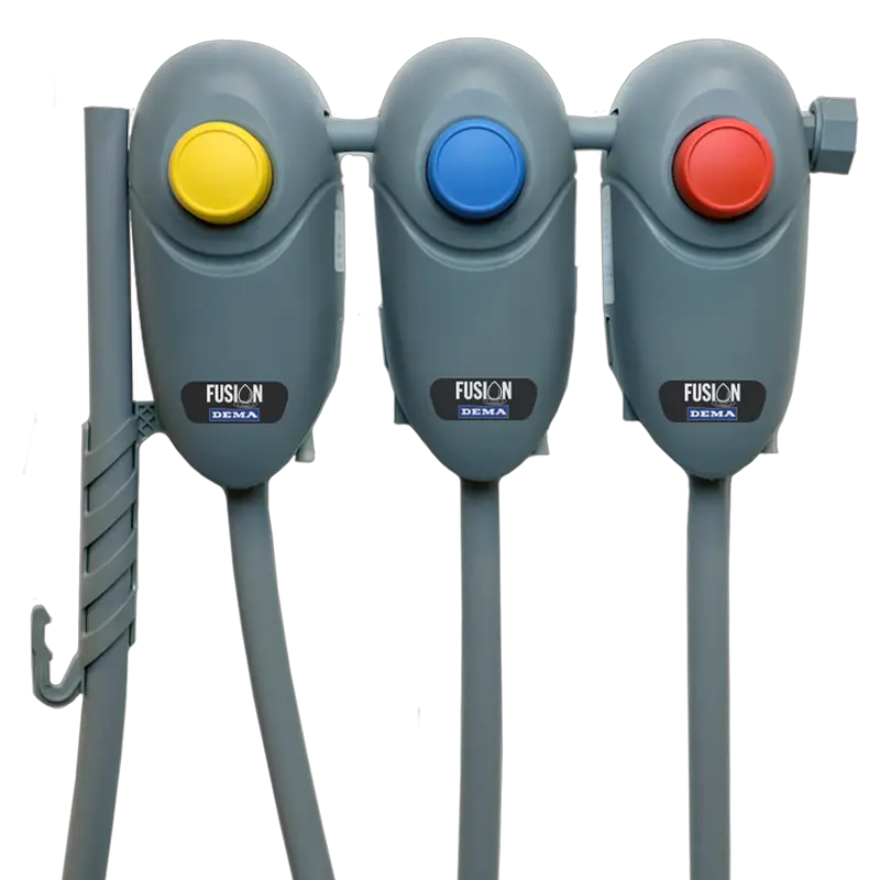
DEMA Fusion One Housekeeping Chemical Dispensing System
Installation and Setup Guide
Fusion One accurately blends proportioned chemical with water for cleaning, sanitizing or `needs. The dispensing system uses a pilot drive water valve designed for easy maintenance. Fusion One is engineered with 1055 approved back flow protect using DEMA’s Air Gap or Action Gap proportioning system.
Warnings
All installations must conform to local plumbing codes and use approved backflow prevention devices. A pressure indicating tee is to be installed with existing faucets according to local plumbing codes in the state of Wisconsin and any other state that requires the use of a pressure indicating tee.
ALWAYS WEAR PROTECTIVE CLOTHING AND EYEWEAR WHEN WORKING WITH CHEMICAL PRODUCTS.
Installation and Servicing
WARNING: INSTALLATION OF DEMA PRODUCTS MUST MEET ALL APPLICABLE PLUMBING CODES AND REGULATIONS ESTABLISHED BY NATIONAL, CITY, COUNTY, PARISH, PROVINCIAL OR OTHER AGENCIES. IT IS POSSIBLE THAT PLUMBING CODES AND REGULATIONS REQUIRE THAT A CERTIFIED INSTALLATION CONTRACTOR OR ENGINEER PERFORM THE PLUMBING INSTALLATION.
- Locate where to install the Fusion One dispenser. Keep the following in mind
- Mount near or over a mop sink.
- Best access to water hookup.
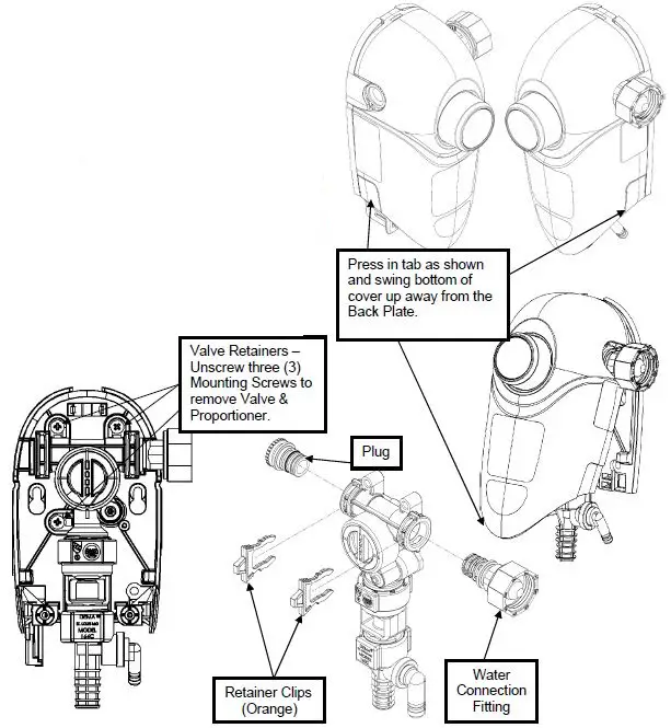
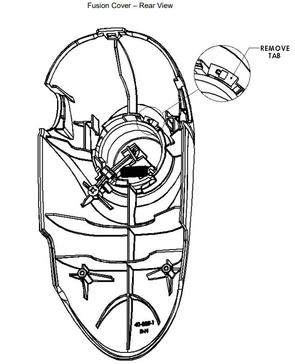
- Remove the Fusion One cover by pressing the plastic tabs on the side of the unit and swing the bottom away from the mounting bracket.
- Determine if the water supply connection should be on the right of left-hand side of the dispenser.
- The entire valve and proportioned assembly can be removed from the mounting bracket (see illustration on this page).
- The water supply connection can be moved to either side by removing the plastic, orange retainer clips, the plug and the water connection fitting. Then replace the retainer clips.

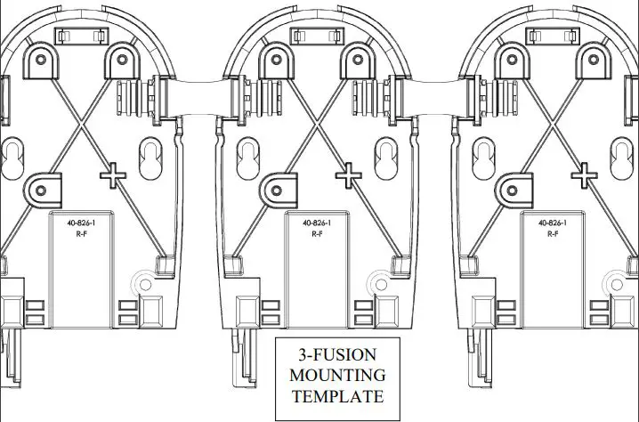
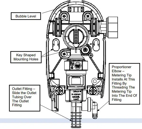
- Locate the 2 key shaped mounting holes in the back plate. Mount the Fusion One using the 2 mounting screws and anchors that are included in the installation kit; with the aid of the integrated bubble level.
- Install the desired metering tip by threading tip into the proportioner chemical pick-up elbow.
- Cut the chemical supply tube to the length allows the foot valve to rest on the bottom of the chemical container. Slide the ceramic weight onto the chemical supply tube until it is against the foot valve. This will keep the foot valve at the bottom of the chemical container.
Note: Chemical containers cannot be greater than 6 feet (1.8M) below the Fusion One dispenser. - Install the Fusion One cover by positioning the top of the cover near the top of dispenser back plate and push the cover back over the valve assembly until the tab latches on side of the unit.
- Connect the water line to the inlet of the Fusion One.
- Note: The water pressure must be between 20psi and 95psi. Optimum chemical induction occurs between 30psi – 60psi.
- The water inlet options for the Fusion One are:
- Garden Hose (female)
- 3/8” Brass Compression Fitting (suitable for 3/8” OD soft copper water line)
- 3/8” John Guest Push-on Water Fitting (suitable for 3/8” OD soft copper or LDPE tubing)
- 3/8” Brass Barb Water Fitting (suitable for 3/8” LDPE tubing)
- The Fusion One can be used in conjunction with a pressure indicating tee, P/N 68.6.QD2.

- Removal of Button Tab to engage Locking Activation feature (for 4GPM Proportioners).
Step 1: Remove Fusion One cover (see #2 above).
Step 2: Break off tab with pliers.
Metering Tip Kits
| Table 1: Fusion Metering Tips 100.15K (Provided) | ||||||
| Metering Tip Color | 1 GPM Air Gap Proportioner | 4 GPM Air Gap Proportioner | ||||
| Oz./gal | ml/L | Ratio : 1 | Oz./gal | ml/L | Ratio : 1 | |
| Tan | 1.37 | 10.57 | 93.65 | 0.37 | 2.91 | 343.19 |
| Orange | 1.67 | 12.91 | 76.48 | 0.44 | 3.45 | 289.14 |
| Turquoise | 1.74 | 13.44 | 73.43 | 0.49 | 3.83 | 260.27 |
| Pink | 3.45 | 26.28 | 37.06 | 0.92 | 7.12 | 139.38 |
| Light Blue | 4.47 | 33.73 | 28.65 | 1.10 | 8.49 | 116.74 |
| Brown | 5.04 | 37.87 | 25.41 | 1.40 | 10.80 | 91.62 |
| Red | 6.89 | 51.08 | 18.58 | 1.78 | 13.70 | 72.01 |
| White | 7.43 | 54.87 | 17.23 | 1.90 | 14.60 | 67.48 |
| Green | 7.46 | 55.06 | 17.16 | 1.98 | 15.26 | 64.53 |
| Blue | 9.14 | 66.63 | 14.01 | 2.54 | 19.44 | 50.45 |
| Yellow | 14.07 | 99.07 | 9.09 | 4.29 | 32.46 | 29.81 |
| Black | 17.36 | 119.45 | 7.37 | 4.53 | 34.19 | 28.25 |
| Purple | 31.36 | 196.81 | 4.08 | 7.67 | 56.53 | 16.69 |
| Gray | 34.95 | 214.51 | 3.66 | 8.77 | 64.15 | 14.59 |
| No Tip | 35.95 | 219.31 | 3.56 | 10.54 | 76.05 | 12.15 |
INDUCTION RATES BASED ON WATER THIN PRODUCTS (1 cps) INDUCTION RATES VARY PRODUCT TO PRODUCT. FIELD TESTS ARE RECOMMENDED
| Table 2: Ultra Lean Metering Tips 100.15KU (Not Provided) | ||||||
| Metering Tip Color | 1 GPM Air Gap Proportioner | 4 GPM Air Gap Proportioner | ||||
| Oz./gal | ml/L | Ratio : 1 | Oz./gal | ml/L | Ratio : 1 | |
| Copper | 0.47 | 3.70 | 269.58 | 0.14 | 1.10 | 904.85 |
| Pumpkin | 0.75 | 5.80 | 171.35 | 0.22 | 1.71 | 585.42 |
| Burgundy | 0.87 | 6.75 | 147.10 | 0.25 | 1.98 | 503.37 |
| Lime Green | 1.07 | 8.26 | 120.14 | 0.31 | 2.44 | 408.69C |
| Table 3: Fusion Metering Tips 100.15K (Provided) | ||||||
| Metering Tip Color | 1 GPM Action Gap Proportioner | 4 GPM Action Gap Proportioner | ||||
| Oz./gal | ml/L | Ratio : 1 | Oz./gal | ml/L | Ratio : 1 | |
| Tan | 0.96 | 7.46 | 133.12 | 0.32 | 2.49 | 399.99 |
| Orange | 1.20 | 9.30 | 106.51 | 0.38 | 2.97 | 335.84 |
| Turquoise | 1.43 | 11.01 | 89.81 | 0.45 | 3.50 | 285.06 |
| Pink | 2.26 | 17.36 | 56.62 | 0.79 | 6.15 | 161.72 |
| Light Blue | 2.87 | 21.95 | 44.56 | 1.01 | 7.81 | 127.09 |
| Brown | 3.40 | 25.86 | 37.68 | 1.20 | 9.30 | 106.48 |
| Red | 4.10 | 31.08 | 31.18 | 1.42 | 10.99 | 89.99 |
| White | 4.67 | 35.18 | 27.43 | 1.67 | 12.86 | 76.79 |
| Green | 4.85 | 36.54 | 26.38 | 1.79 | 13.81 | 71.40 |
| Blue | 6.96 | 51.58 | 18.39 | 2.46 | 18.83 | 52.10 |
| Yellow | 10.27 | 74.31 | 12.46 | 3.79 | 28.79 | 33.74 |
| Black | 12.90 | 91.59 | 9.92 | 4.86 | 36.59 | 26.34 |
| Purple | 26.69 | 172.54 | 4.80 | 11.31 | 81.19 | 11.32 |
| Gray | 30.36 | 191.72 | 4.22 | 13.76 | 97.10 | 9.30 |
| No Tip | 45.48 | 262.17 | 2.81 | 24.77 | 162.15 | 5.17 |
| Table 4: Ultra Lean Metering Tips 100.15KU (Not Provided) | ||||||
| Metering Tip Color | 1 GPM Action Gap Proportioner | 4 GPM Action Gap Proportioner | ||||
| Oz./gal | ml/L | Ratio : 1 | Oz./gal | ml/L | Ratio : 1 | |
| Copper | 0.34 | 2.67 | 373.60 | 0.12 | 0.94 | 1060.18 |
| Pumpkin | 0.56 | 4.33 | 230.23 | 0.19 | 1.50 | 665.14 |
| Burgundy | 0.77 | 6.00 | 165.66 | 0.24 | 1.85 | 539.29 |
| Lime Green | 0.84 | 6.52 | 152.39 | 0.28 | 2.21 | 451.24 |
Replacement Parts: Fusion Unit
Fusion One units can be connected using the Fusion Valve Connector (41.186.1). It would replace the Plug Adapter (40.926.1) on one of the units, and the Inlet Adapter Assembly (40.925.1 & 40.925.2) of the other nit. Please use the orange retainer clips (40.854.1), to secure the connector in place. 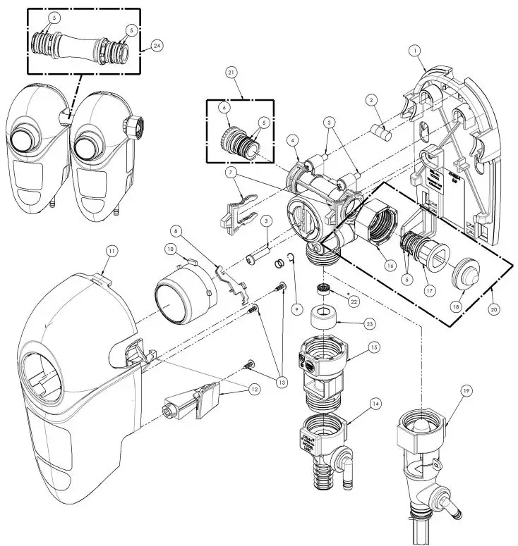
| FUSION REPLACEMENT PARTS | |||||
| Item No. | DEMA Part No. | QTY | DESCRIPTION | ||
| 1 | 40.826.1 | 1 | BASE, FUSION HK | ||
| 2 | 40.970.1 | 1 | FUSION BUBBLE LEVEL | ||
| 3 | 44.116.3 | 3 | #8 HI-LO SCREW X 1″ LONG | ||
| 4 | 40.847.2 | 1 | FUSION VALVE ASSEMBLY (SEE PG. #7 FOR PARTS) | ||
| 5 | 63.78 | 4 | O-RING-SEAL EPT (7/16″I.D. X 3/8″O.D. X 1/16″ NOM.) | ||
| 6 | 40.853.1 | 1 | END PLUG PILOT ACTIVATED VALVE | ||
| 7 | 40.854.1 | 2 | RETAINING CLIP PILOT ACTIVATED VALVE | ||
| 8 | 40.931.1 | 1 | BOTTOM LEVER, FUSION HK | ||
| 9 | 40292.1 | 1 | EXTENSION SPRING | ||
| 10 | 40.929.1 | 1 | BUTTON, FUSION HK | ||
| 11 | 41.185.1 | 1 | FRONT COVER, FUSION, W/LABELS | ||
| 12 | 40.930.1 | 1 | RETENTION LATCH | ||
| 13 | 81.20.2 | 2 | #4 X 3/8″ HI LO SCREW | ||
| 14 | 61.22.3 | 1 | ACTION GAP PROPORTIONER ASSEMBLY (4GPM) | ||
| 15 | 16.30 | 1 | ACTION GAP | ||
| 16 | 65.10.2 | 1 | STANDARD COUPLING, GARDEN HOSE THREAD | ||
| 16 | 98.55.1 | 1 | EURO COUPLING, BRITISH HOSE THREAD | ||
| 17 | 40.852.1 | 1 | WATER INLET FITTING, PILOT ACTIVITED VALVE | ||
| 18 | 100.38 | 1 | STRAINER WASHER | ||
| 19 | 61.22.3BAG | 1 | AIR GAP PROPORTIONER ASSEMBLY (4GPM) | ||
| 20 | 40.925.1 | 1 | FUSION VALVE INLET ADAPTER W/GHT, ASSEMBLY | ||
| 20 | 40.925.2 | 1 | FUSION VALVE INLET ADAPTER W/BRITISH PSPP, ASSEMBLY | ||
| 20 | 40.925.3 | 1 | FUSION VALVE INLET ADAPTER W/GHT, ASSEMBLY, PLASTIC | ||
| 20 | 40.925.4 | 1 | FUSION VALVE INLET ADAPTER W/BSPP, ASSEMBLY, PLASTIC | ||
| 21 | 40.926.1 | 1 | FUSION VALVE PLUG ADAPTER, ASSEMBLY | ||
| 22 | 77.2.1.06 | 1 | FLOW DISC, PINK, [1.06(GPM) / 4(L/MIN)] *Not Installed W/Air Gap Models* | ||
| 22 | 77.6.2.64 | 1 | FLOW DISC, YELLOW, [2.64(GPM) / 10(L/MIN)] | ||
| 22 | 40.570.1 | 1 | FLOW DISC, NATURAL, [4.45(GPM) / 16.85(L/MIN)] | ||
| 23 | 89.18.1 | 1 | RETAINER, FLOW DISC | ||
| 24 | 41.186.1 | – | FUSION VALVE CONNECTOR | ||
| 25 | 89.30.GAP | 1 | HOSE HANGER ASSY. FOR GAP MODELS ONLY | ||
Replacement Parts Valve Body 
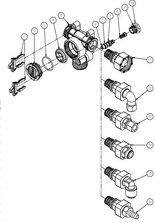
| VALVE REPLACEMENT PARTS | |||
| Item No. | DEMA Part No. | QTY | DESCRIPTION |
| 1 | 40.854.1 | 2 | RETAINING CLIP PILOT ACTIVATED VALVE |
| 2 | 41.058.1 | 1 | DIAPHRAGM CAP |
| 3 | 619.21 | 1 | O-RING SEAL EPDM (15/16” X 1/16”) |
| 4 | 98.26.1 | 1 | 1-1/16″ DIAPHRAGM |
| 5 | 40.824.1 | 1 | VALVE BODY |
| 6 | 40.849.1 | 1 | BUTTON, PILOT ACTIVATED VALVE |
| 7 | 640.106 | 2 | O-RING SEAL (3/16″ID X 3/8″OD X 3/32″NOM.) |
| 8 | 98.39.2 | 1 | RETURN SPRING |
| 9 | 63.78 | 1 | O-RING-SEAL EPT (7/16″I.D. X 9/16″O.D. X 1/16 NOM.) |
| 10 | 40.851.1 | 1 | BOTTOM CAP |
| 11 | 40.925.1 | 1 | FUSION INLET ADAPTER W/GHT |
| 11 | 40.925.2 | 1 | FUSION INLET ADAPTER W/BSPP |
| 11 | 40.925.3 | 1 | FUSION INLET ADAPTER W/GHT, PLASTIC |
| 11 | 40.925.4 | 1 | FUSION INLET ADAPTER W/BSPP, PLASTIC |
| 12 | 40.927.1 | 1 | 3/8” ELBOW COMPRESSION INLET FITTING |
| 13 | 40.927.2 | 1 | 3/8” STRAIGHT COMPRESSION INLET FITTING |
| 14 | 40.927.3 | 1 | 3/8” JOHN GUEST PUSH-ON INLET FITTING |
| 15 | 40.927.4 | 1 | 3/8” ELBOW JOHN GUEST PUSH-ON INLET FITTING |
| 16 | 40.927.5 | 1 | 3/8” BARB INLET FITTING |
Trouble Shooting
| Symptom | Probable Cause | Remedy |
|
Water Valve Does Not Shut Off After Use | Water pressure is above recommended range | Recommended water pressure is 30-70psi (2-5bar), install #66.43 pressure regulator |
| Hole in the diaphragm | Replace the diaphragm | |
| Debris on the diaphragm or the valve actuation button | Rinse the diaphragm or button assembly | |
| Proportioner Continues To Draw Chemical After Water Valve Is Shut Off | Concentrated chemical is positioned higher than the proportioner and is siphoning chemical | Move chemical container so it is lower than the proportioner |
| Activation Button Does Not Return To Off Position | Spring is missing from button | Replace spring, #64.50.1 |
|
Proportioner Does Not Draw Chemical Properly | Insufficient water pressure | Minimum allowable water pressure is 20psi (1.38bar) |
| Foot valve/SafeLink cap is clogged | Soak in hot water to clean | |
| Metering tip is clogged | Soak in hot water to clean | |
| Mineral deposits are located on air gap nozzle | Soak nozzle and inlet screen in hot water or in a mineral deposit removal chemical | |
| Proportioner elbow is loose, or O-ring seal has failed, allowing air in | Tighten seal, inspect O-ring condition, replace if needed, #63.78 | |
| Air Gap Is Spraying Or Dripping | Mineral deposits are located on air gap nozzle | Soak nozzle and inlet screen in hot water or in a mineral deposit removal chemical |
| Leaking At Action Gap | Bucket fill tube is raised higher than proportioner | Do not raise bucket fill tube higher than proportioner, ensure dispenser is mounted a minimum of 4′ (1.2m) off floor |
| Leaking At Water Valve Fittings | Retainer clip (orange) is not present | Replace retainer clip, #40.854.1 |
| Leaking At Threaded Connections | Connection between dispenser and water supply is too loose or strainer washer is missing | Inspect connection, verify strainer washer is present, tighten fittings |
| Leaking At Threaded Connections | Connection between dispenser and water supply is too loose or strainer washer is missing | Inspect connections, tighten fittings |
| Proportioner and/or backflow preventer is too loose | Inspect connections, tighten fittings |
Product Dimensions 
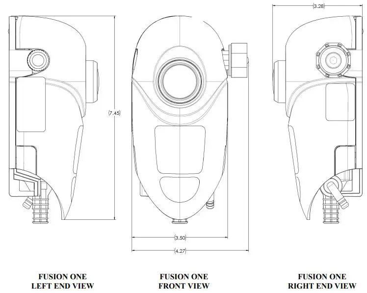
Specifications
- Operation Pressure Rating: 20psi – 95psi
- Safety Pressure Rating: 125psi
- Water Temperature Rating: 45ºF (7ºC) – 125ºF (50ºC) Max
- Back Flow Protection – ASSE 1055 (Action Gap & Air Gap)
- ASME A112.1.2 (Air Gap)
Warranty
Merchandise Returns: No Merchandise Will Be Returned For Credit Without DEMA’S Written Permission. Returned Merchandise Authorization Number Is Required In Advance Of Return.
Product Warranty
DEMA products are warranted against defective material and workmanship under normal use and service for one year from the date of manufacture. This limited warranty does not apply to any products that have a normal life shorter than one year or failure and damage caused by chemicals, corrosion, physical abuse, or misapplication. Rubber and synthetic rubber parts such as “o”-rings, diaphragms, PVC tubing, and gaskets are considered expendable and are not covered under warranty. This warranty is extended only to the original buyer of DEMA products. If products are altered or repaired without prior approval DEMA, this warranty is void. Defective units or parts should be returned to the factory with transportation prepaid. If inspection shows them to be defective, they will be repaired or replaced without charge, F.O.B. factory. DEMA assumes no liability for damages. Return merchandise authorization number must be granted in advance of return units for repair or replacement (See “Merchandise Returns” above).