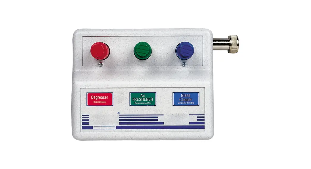
![]() 681AG-5 Blend Center
681AG-5 Blend Center
Instruction Manual
PARTS
A. 1 pc. Blend center assembly.
B. 5 pc. 1/4 in. I.D. or 3/8 in. I.D. x 8 ft. long vinyl supply tubing, foot valve, and ceramic weight.
C. 1 pc. 9/16 in. I.D. x 20 ft. long vinyl outlet tubing.
D. 2 pc. #8 pan head 3/4 in screws & anchors.
E. 1 pc. label card.
F. 1 pc. Metering tip kit (3/8 in.: 61-9K) (1/4 in.: 10015K)
INSTALLATION:
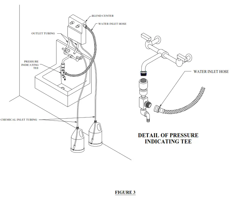
Note: Pressure-indicating tee is to be installed with existing faucets according to local plumbing codes in the state of Wisconsin and any other state that requires the use of a pressure-indicating tee.
This product is designed only to be used as described in this instruction sheet. Adhere to all warnings and cautions identified in this document.
![]() WARNING: Installations must conform to all local and national plumbing codes and use approved backflow prevention and pressure relief devices where required.
WARNING: Installations must conform to all local and national plumbing codes and use approved backflow prevention and pressure relief devices where required.
ALWAYS DISCONNECT THE DISPENSER FROM THE WATER SOURCE WHEN DISPENSER IS NOT IN USE.![]() Always read SDS for all chemicals used and follow personal protective guidelines.
Always read SDS for all chemicals used and follow personal protective guidelines.
A. Mounting and water supply:
Remove the Blend Center lid and hold the unit in position to locate the mounting screw positions. Install the mounting screws; leaving approximately 1/8 in. extension between the wall and screw head. Mount the Blend Center by inserting the screw heads through the keyhole slots in the base and tighten the screws (See Figure 1). The water inlet is equipped with a female garden hose fitting (with a strainer washer) for attaching a water supply hose. The fitting may be removed to permit direct connection to a 3/8 in. NPT pipe. The unit is designed so water can be supplied to either side by interchanging the pipe plug and the female hose fitting.
B. Pressure Indicating Tee Installation:
Screw female quick disconnect to the faucet and attach pressure indicating tee to female quick disconnect. Attach the female end of the reinforced hose to the male threads of the tee, then attach the male end to the female garden hose fitting at the water inlet of the Blend Center (See Figure 3). The water supply should not exceed 125 psi and the water temperature must not exceed 160°F.
C. Chemical supply:
Place the chemical containers in a convenient location not more than 6 ft. below the blend center (greater lifts will reduce injection capacities). Insert the vinyl supply tubing with the foot valve ends into the chemical containers. Cut the vinyl tubes to any convenient length that will allow them to extend from the bottom of the chemical container to the proportioner inlet barbs. (See figure 1). Gummed labels are provided for product labeling.
D. Outlet:
Cut the 9/16 in. I.D. outlet tubing to the desired lengths and attach them to the proportioner outlets. Longer lengths may be used up to 10 ft. The 7-in. long tubing must be left on the 1 GPM proportioner to insure priming.
E. Chemical injection adjustment:
- Dilution Control: Chemical feed rates are controlled by metering tips screwed into the proportioner barbs. Select a tip for each barb using Tables 1-4 as a guide.
- Viscosity 1 cps (centipoise) is equal to the viscosity of water, 75 cups is approximately equal to the viscosity of 10-weight motor oil, and 200 cups is approximately equal to the viscosity of most dishwashing detergents.
OPERATION
The Blend Center is now ready for use. Depressing a push button opens the valve, allowing water to flow through the chemical proportioner that mixes chemicals at the desired rate. The buttons are spring-loaded to prevent accidental overflow if unattended but may be converted to locking buttons by cutting off the tab at the notch. (See Figure 2) Pushing the button and tubing it 1/4 turn clockwise at the end of its travel allows the valve to lock on. This makes it unnecessary for the attendant to hold the button while filling large containers. Turning the button in a counterclockwise direction will release it, allowing the valve to shut off.
SERVICING
A. Proportioner fails to draw chemicals.
- Pinch the outlet tube to create back pressure which will cause the unit to prime. The foot valve will keep the inlet tube primed.
- Insufficient water supply pressure. 20 psi. is the minimum allowable.
B. Proportioner stops drawing chemicals.
- Inspect the foot valve for dried chemicals or dirt. Soak in hot water to clean.
- Proportioner metering tip clogged with the dried chemical. Remove the tip and try injecting hot water to clear interior passages.
C. Proportioner continues to draw chemicals after the water valve closes.
The chemical supply is higher than the bottom of the discharge tube creating a natural siphon. Lower the chemical supply or hang up the outlet tubing after use.
D. Valve malfunction.
Check that the button moves freely up & down and that a “click” can be heard when the button is pushed and released, indicating that the magnet is activating the plunger properly. Remove cover. To inspect internal parts, unscrew the magnet housing and carefully pull off the enclosing tube so as not to drop the plunger, kick-off spring, and spacer. Check for dirt or damage to the impending plunger and kick-off spring movement. Inspect the diaphragm, making sure the two small pin holes (bleed holes) in the diaphragm convolution are clear to allow the valve to close.
Caution: When servicing the unit, be sure that replacement parts have been installed according to the drawing.
TABLE 1 – 164 AG (1 GPM flow rate proportioner – 1/4 in. barb and tubing)
| Metering Tip Color | 1 cps | 75 cps | 200 cps | |||
| Oz./Gal. | Ratio | Oz./Gal. | Ratio | Oz./Gal. | Ratio | |
| Tan | 1. | 102-1 | 0.90 | 142-1 | 0.60 | 213-1 |
| Orange | 1.70 | 75-1 | 1.20 | 107-1 | 0.80 | 160-1 |
| Turquoise | 2. | 60-1 | 2. | 83-1 | 1.10 | 116-1 |
| Pink | 3.00 | 43-1 | 2.00 | 64-1 | 1.50 | 85-1 |
| Light Blue* | 3.90 | 33-1 | 3. | 47-1 | 1.80 | 71-1 |
| Brown | 5. | 28-1 | 3.00 | 43-1 | 2.00 | 64-1 |
| Red | 5.80 | 22-1 | 3.60 | 36-1 | 2.30 | 56-1 |
| White | 7.00 | 18-1 | 4. | 29-1 | 2.70 | 47-1 |
| Green | 7.90 | 16-1 | 5.00 | 26-1 | 3.00 | 43-1 |
| Blue | 9.80 | 13-1 | 6. | 22-1 | 3.30 | 39-1 |
| Yellow | 14.80 | 9-1 | 7. | 17-1 | 4. | 36-I |
| Black | 20. | 6-1 | 8.50 | 15-1 | 3.70 | 35- I |
| Purple | 27.80 | 5-1 | 9.80 | 13-1 | 3.80 | 34-I |
| Gray | 31.60 | 4-1 | 10.50 | 12-1 | 3.90 | 33- I |
| No Tip | 35.70 | 3.6-1 | 11.80 | 11-1 | 4.50 | 28-I |
* Metering tip color was formerly clear. Leaner dilutions can be achieved by ordering DEMA ultra lean metering tip kit 100-15KU.
TABLE 2 – 164 AG (1 GPM flow rate proportioner – 3/8 in. barb and tubing)
| Metering Tip Color | Injection Rates For Viscosities Shown | |||||
| 1 cps | 75 cps | 200 cps | ||||
| Oz./Gal. | Ratio | Oz./Gal. | Ratio | Oz./Gal. | Ratio | |
| Clear | 1.40 | 91-1 | 1.00 | 128-1 | 0.85 | 151-1 |
| Purple | 2. | 60-1 | 2. | 73-1 | 1.40 | 91-1 |
| Yellow | 4.00 | 32-1 | 3. | 39-I | 2.80 | 46-1 |
| Green | 6.70 | 19-1 | 5.40 | 24-1 | 4.50 | 28-1 |
| Pink | 8.70 | 15-1 | 7.00 | 18-1 | 5.60 | 23-1 |
| Turquoise | 14. | 9-1 | 11. | 11-1 | 8. | 16-1 |
| Black | 17. | 7-1 | 13.50 | 9-1 | 10.00 | 13-1 |
| Gray | 22.60 | 6-1 | 17. | 8-1 | 11.60 | 11-1 |
| Red | 25. | 5-1 | 19.50 | 7-1 | 13.50 | 10-1 |
| Blue | 27.50 | 4.7-1 | 22. | 6-1 | 14. | 9-1 |
| Brown | 31.00 | 4-1 | 24. | 5-1 | 15.60 | 8-1 |
| White | 33.50 | 3.8-1 | 26. | 4.9-1 | 16.70 | 7.7-1 |
| Orange | 35.40 | 3.6-1 | 28.00 | 4.6-1 | 17.40 | 7.4-1 |
| Lt. Blue* | 36.50 | 3.5-1 | 29.00 | 4.4-1 | 18.20 | 7-1 |
| Tan* | 37.80 | 3.4-1 | 29.90 | 4.3-1 | 19. | 6.9-1 |
| No Tip | 38.30 | 3.3-1 | 30.90 | 4.1-1 | 21.30 | 6-1 |
Note: All induction rates are based on water pressure of 40 psi. * These tips are not included in the standard tip pack.
TABLE 3 – 163 AG (4 GPM flow rate proportioner – 1/4 in. barb and tubing)
| Metering Tip Color | Injection Rates For Viscosities Shown | |||||
| 1 cps | 75 cps | 200 cps | ||||
| Oz./Gal. | Ratio | Oz./Gal. | Ratio | Oz./Gal. | Ratio | |
| Clear | 1.40 | 91-1 | 1.00 | 128-1 | 0.85 | 151-1 |
| Purple | 2. | 60-1 | 2. | 73-1 | 1.40 | 91-1 |
| Yellow | 4.00 | 32-1 | 3. | 39-I | 2.80 | 46-1 |
| Green | 6.70 | 19-1 | 5.40 | 24-1 | 4.50 | 28-1 |
| Pink | 8.70 | 15-1 | 7.00 | 18-1 | 5.60 | 23-1 |
| Turquoise | 14. | 9-1 | 11. | 11-1 | 8. | 16-1 |
| Black | 17. | 7-1 | 13.50 | 9-1 | 10.00 | 13-1 |
| Gray | 22.60 | 6-1 | 17. | 8-1 | 11.60 | 11-1 |
| Red | 25. | 5-1 | 19.50 | 7-1 | 13.50 | 10-1 |
| Blue | 27.50 | 4.7-1 | 22. | 6-1 | 14. | 9-1 |
| Brown | 31.00 | 4-1 | 24. | 5-1 | 15.60 | 8-1 |
| White | 33.50 | 3.8-1 | 26. | 4.9-1 | 16.70 | 7.7-1 |
| Orange | 35.40 | 3.6-1 | 28.00 | 4.6-1 | 17.40 | 7.4-1 |
| Lt. Blue* | 36.50 | 3.5-1 | 29.00 | 4.4-1 | 18.20 | 7-1 |
| Tan* | 37.80 | 3.4-1 | 29.90 | 4.3-1 | 19. | 6.9-1 |
| No Tip | 38.30 | 3.3-1 | 30.90 | 4.1-1 | 21.30 | 6-1 |
* Metering tip color was formerly clear. Leaner dilutions can be achieved by ordering DEMA ultra lean metering tip kit 10015KU.
TABLE 4 – 163 AG (4 GPM flow rate proportioner – 3/8 in. barb and tubing)
| Metering Tip Color | Injection Rates For Viscosities Shown | |||||
| 1 cps 75 cps | 200 cps | |||||
| Oz./Gal. Ratio | Oz./Gal. | Ratio | Oz./Gal. | Ratio | ||
| Clear | 0.90 | 142-1 | 0.30 | 427-1 | 0.20 | 640-1 |
| Purple | 1.10 | 116-1 | 0.50 | 256-1 | 0.40 | 320-1 |
| Yellow | 1.80 | 71-1 | 1.00 | 128-1 | 0.70 | 183-1 |
| Green | 2.50 | 51-1 | 1.50 | 85-1 | 1.20 | 107-1 |
| Pink | 3.00 | 43-1 | 2.00 | 64-1 | 1.50 | 85-1 |
| Turquoise | 4.50 | 28-1 | 3. | 41-1 | 2.30 | 56-1 |
| Black | 4.80 | 27-1 | 4. | 34-1 | 2.80 | 46-1 |
| Gray | 6.70 | 19-1 | 4.80 | 27-1 | 3. | 38-1 |
| Red | 8. | 16-1 | 5.80 | 22-1 | 3.80 | 34-1 |
| Blue | 9.20 | 14-1 | 6.60 | 19-1 | 4.20 | 30-1 |
| Brown | 11.10 | 12-1 | 8. | 17-1 | 4.70 | 27-1 |
| White | 13.20 | 10-1 | 9. | 14-1 | 5.00 | 26-1 |
| Orange | 15.00 | 9-1 | 10.10 | 13-1 | 5.30 | 24-1 |
| Lt. Blue* | 16.70 | 8-1 | 11.10 | 12-1 | 5.50 | 23-1 |
| Tan* | 18.50 | 7-1 | 11.80 | 11-1 | 5.80 | 22-1 |
| No Tip | 19.40 | 6.6-1 | 13.00 | 10-1 | 6.20 | 21-1 |
Note: All induction rates are based on water pressure of 40 psi. * These tips are not included in the standard tip pack.
RETURNS: NO MERCHANDISE MAY BE RETURNED FOR CREDIT WITHOUT DEMA’S WRITTEN PERMISSION.
RETURN MERCHANDISE AUTHORIZATION NUMBER REQUIRED IN ADVANCE OF RETURN.
WARRANTY: DEMA products are warranted against defective material and workmanship under normal use and service for one year from the date of manufacture. This limited warranty does not apply to any products which have a normal life shorter than one year or failure and damage caused by chemicals, corrosion, improper voltage supply, physical abuse, or misapplication. Rubber and synthetic rubber parts such as “O”- rings, diaphragms, squeeze tubing, and gaskets are considered expendable and are not covered under warranty. This warranty is extended only to the original buyer of DEMA products. If products are altered or repaired without prior approval of DEMA, this warranty will be void.
Defective units or parts should be returned to the factory with transportation prepaid. If inspection shows them to be defective, they will be repaired or replaced without charge, the F.O.B. factory. DEMA assumes no liability for damages.
Return merchandise authorization number, to return units for repair or replacement, must be granted in advance of return.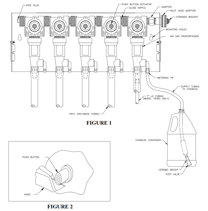
PRESSURE INDICATING TEE INSTALLATION
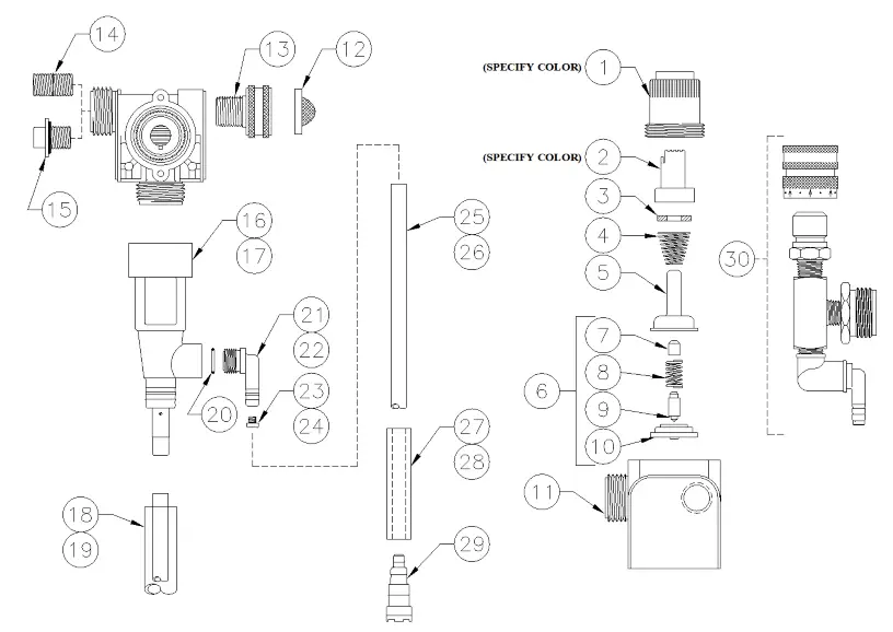
| NO. | PART NO. | DESCRIPTION |
| 1 | 66-139 | MAGNET HOUSING |
| 2 | 66-140 | PUSH BUTTON |
| 3 | 63-35 | MAGNET |
| 4 | 63-36 | SPRING |
| 5 | 41-7-25 | ENCLOSING TUBE |
| 6 | 63-87 | VALVE REPAIR MT |
| 7 | 63-37 | SPACER |
| 8 | 41-1-8 | KICKOFF SPRING |
| 9 | 63-38 | PLUNGER |
| 10 | 41-15-10 | DIAPHRAGM, EP |
| 11 | 63-39 | VALVE BODY |
| 12 | 100-38 | STRAINER WASHER |
| 13 | 93-44 | PIPE TO GARDEN HOSE ADAPTOR |
| 14 | 66-31 | CLOSE NIPPLE |
| 15 | 66-153 | PIPE PLUG ASSY |
| 16 | 61-22GAP-2 | 4 GPM PROPORTIONER (WHITE) |
| 17 | 61-99GAP-2 | 1 GPM PROPORTIONER (GREEN) |
| 18 | 61-21 | ‘AN” ID X 6’ LONG VINYL OUTLET TUBE (4 GPM) |
| 19 | 16-3-6 | 1/3″ ID X 6′ LONG VINYL OUTLET TUBE (1 GPM) |
| 20 | 63-78 | 0-RING EP |
| 21 | 63-79 | INLET BARB (1/4″) |
| 22 | 63-80 | INLET BARB (3/8″) |
| 23 | 100-15K | METERING TIP KIT (1/4″ BARB) |
| 24 | 61-9K | METERING TIP MT (3/8″ BARB) |
| 25 | 100-12 | ‘AN” ID X 8’ LONG VINYL SUPPLY TUBING |
| 26 | 100-12L | 3/8″ ID X 8′ LONG VINYL SUPPLY TUBING |
| 27 | 61-107-2 | CERAMIC WEIGHT FOR 1/4″ TUBING |
| 28 | 61-107 | CERAMIC WEIGHT FOR 3/8″ TUBING |
| 29 | 100-16E-1 | FOOT VALVE |
| 30 | 68-6-QD2 | PRESSURE INDICATING TEE |
I-500
Rev. D-4784


