ggm gastro GPOE430DN Pizza Oven
GENERAL INFORMATION
Before installing the appliance, read operation and maintenance instructions carefully. Wrong installation and part changing may damage the product or may cause injury on people. These are not in our company’s responsibility to damage the appliance intentionally, negligence, detriments because of disobeying instructions and regulations, wrong connections. Unauthorized intervention to appliance invalidates the warranty
- This instruction manual should be kept in a safe place for future reference.
- Installation should be made in accordance with ordinances and security rules of that country by a qualified service personnel.
- This appliance has to be used by trained person.
- Please turn off the appliance immediately in the event of malfunction or failure. The appliance should be repaired only by authorized service personnel. Please demand original spare part.
PRODUCT DESCRIPTION
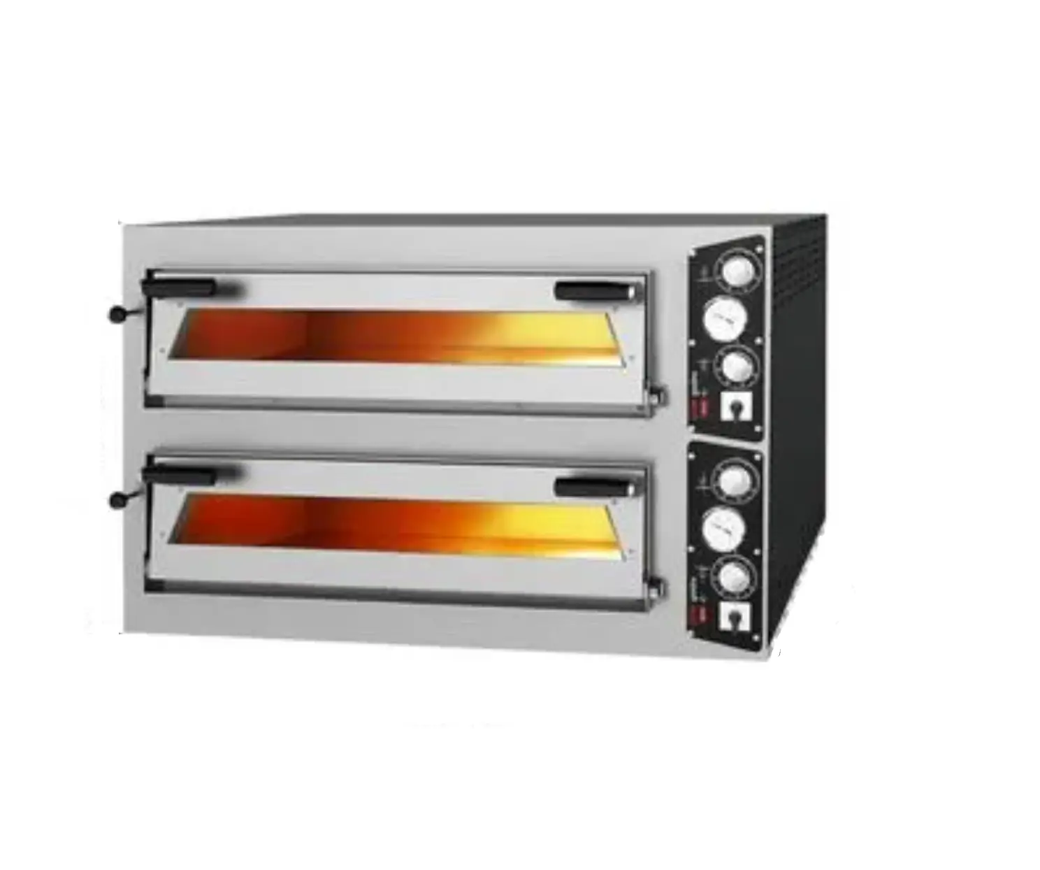
*The Professional Pizza Ovens (Gas) ,that provides high efficiency has been designed to be used in industrial kitchen.
| Product Code | Dimensions (mm) | Weight (kg) | Packaging Dimensions (mm) |
| GPOE430DN | 1100x950x520 | 125 | 1120x960x660 |
| GPOE630DN | 1400x950x520 | 161 | 1450x1000x660 |
| GPOE930DN | 1400x1250x520 | 200 | 1470x1280x660 |
TECHNICAL INFORMATION
| PRODUCT CODE | GPOE430DN | GPOE630DN | GPOE930DN |
| INNER DIMENSIONS (mm) | 615x615x150 | 915x615x150 | 915x915x150 |
| CAPACITY | Ø300 mm x 4 pizza | Ø300 mm x 6 pizza | Ø300 mm x 9 pizza |
| GAS POWER LPG (KW) | 15,5 | 15,5 | 24,2 |
| GAS POWER NG (KW) | 16,1 | 16,1 | 22 |
| ELECTRIC POWER (KW) | 12 | 18 | 24 |
| OPERATING VOLTAGE (V) | 1×230 | 1×230 | 1×230 |
| GAS CONSUMPTION (NG) | 1,70 m³/h | 1,70 m³/h | 2,30 m³/h |
| GAS CONSUMPTION (LPG) | 1,21 kg/h | 1,21 kg/h | 1,90 kg/h |
| OPERATING PRESSURE (mbar) | 30 | 30 | 30 |
| FEEDING CABLE | 3×2,5 | 3×2,5 | 3×2,5 |
TRANSPORTATION
*This appliance can not be moved by hand from area to area.It must be moved on pallet with forklift truck
UNPACKING
- Please unpack the package according to the security codes and ordinances of current country and get rid from the pack. Parts which contacts with food are produced by stainless steel. All plastic parts are marked by material’s symbol.
- Please check that all the parts of appliance had come completely and if they are damaged or not during the shipping.
INSTALLATION
- Please place the product to straight and sturdy ground, please take necessary steps against possibility of overturn.
- Technician who will serve for installation and service for the appliance must be professional on this subject and must have installation and service licenses by the company.
- Connection to Gas Fitment must be done by authorized person.
- The area where the appliance is must have enough ventilation and vent-hole.
- The appliance must be connected correctly according to local and national gas standards of your country.
- The appliance gas entrances are indicated with ‘’G’’ label on the body.
 This appliance must be connected to an earthed outlet in accordance with safety rules and standards.
- Appliance’s earthing must be connected to earthing line on panel which is nearest to electric installation.
- Connection to the main fuse and leak current fuse must be done in accordance with the current regulations.
- Connection to gas fitment must be done with suitable diameter metal flex pipe and spheric valve.
- The spheric valve must be immobilized to a place that is far away from heat and accessible during the danger. After gas entrance connection done, gas leakages must be checked.
- According to the datas on appliance information plate, gas and pressure must be adjusted. If the gas type that is adjusted is not the suitable with gas type that is at installation place, apply the instructions that is about adjustment of different gas type (Event :G)
- For easy cleaning and maintenance of the appliance, there must be at least 50 cm spaces both right and left side of the appliance.
SAFETY INSTRUCTIONS
- Do not use the appliance in insufficient lighted place.
- Do not touch the moving attachments while the appliance operates.
- Do not install the appliance in the presence of flammable or explosive materials.
- Do not operate the appliance when the machine is empty.
- Do not load so less or more than appliance’s capacity.
- Do not attempt to use the appliance without suitable protective equipment’s.
- Do not open the oven lid when the cooking compartment is hot.
- Because of any reason if there is a fire or flame flare where the appliance is used,turn off all gas valves and electric contactor switch quickly and use fire extinguisher .Never use water to extinguish the fire.
- If there is gas leakage where the appliance is, .do not fire absolutely and do not use electric.
- Definitely do not allow to check the sealing with flame.
- The chimney hood must be installed to the oven as it covers over the oven completely. The chimney hood pipes can be used without fan till maximum 3 metres. If the chimney hood pipe distance is more than 3 metres,the fan must be used.
OPERATION
* Control panel:
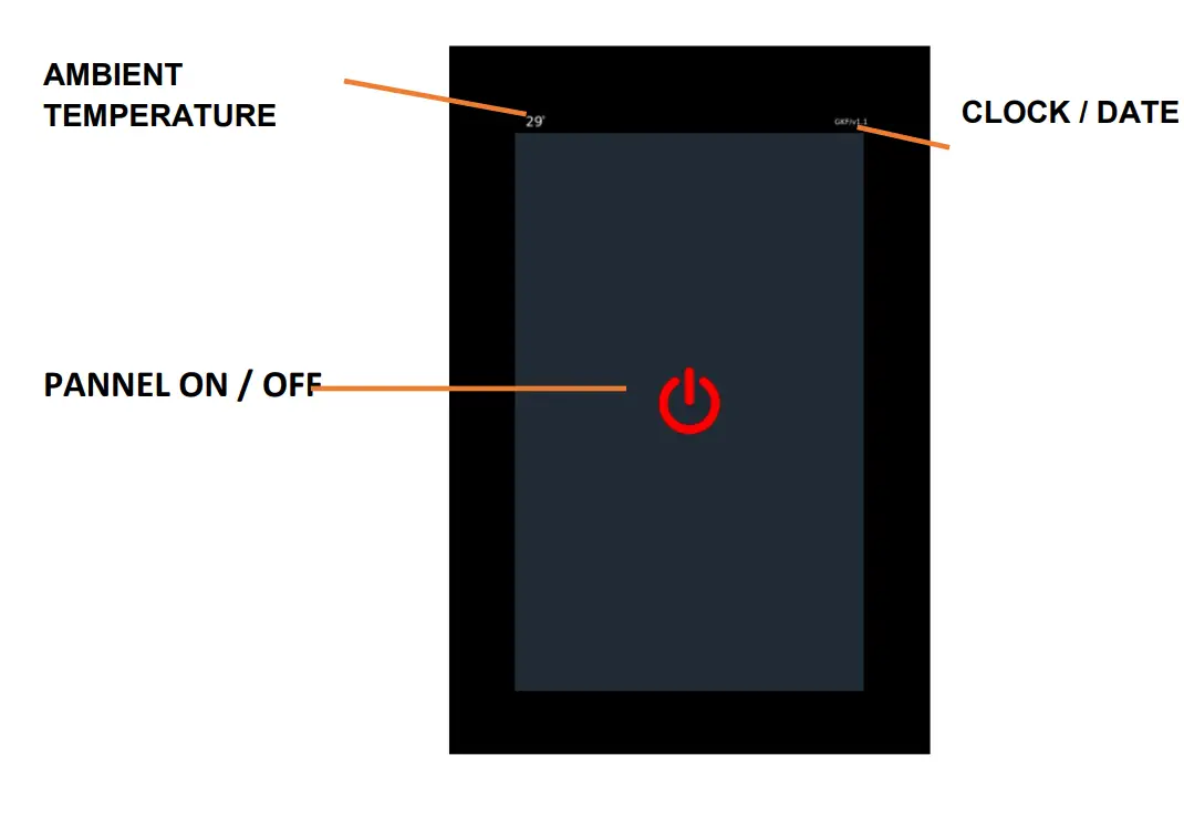
MAIN SCREEN
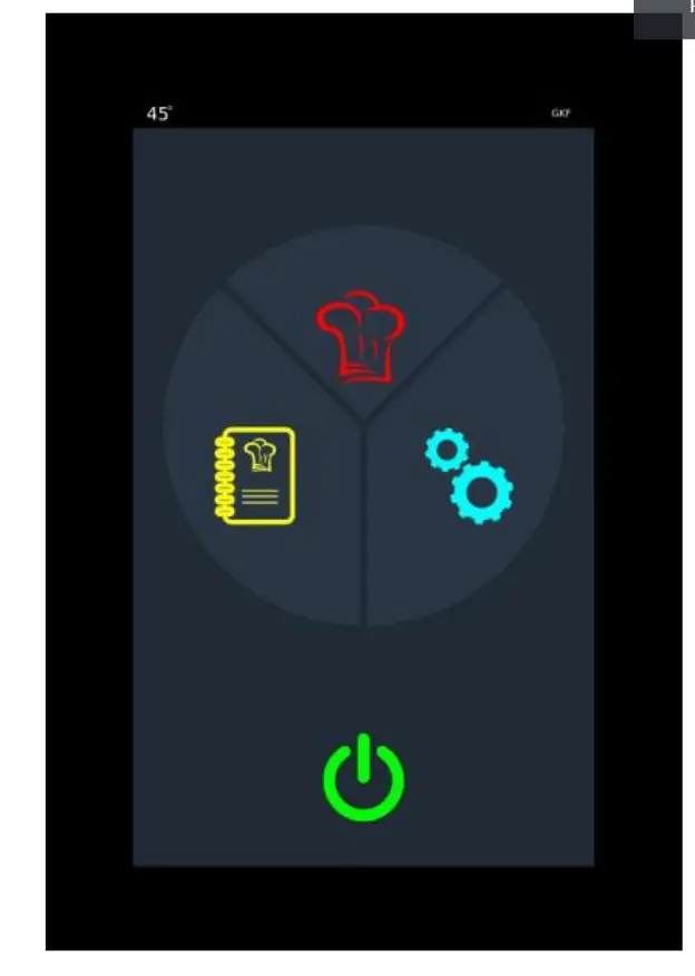
 | MANUEL COOKING If cooking will be done manually, click here |
 | RECIPE COOKING if recipe cooking or recipe creation is to be made, click here |
 | SETTINGS The parameters, Time / date setting and Auto start are set here. |
 | ON/OFF BUTTON |
MANUAL COOKING
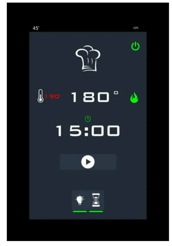
| TEMPERATURE Oven temperature, set value and heaters status are shown here. If the heater icon is red, the heater output is passive, if the heater icon is green, the heater is active. | |
 | COOKING TIME From here, cooking time can be set and started. At the end of this period, the alarm is activated and the expiration warning appears on the screen. At the end of the period, the countdown can be continued with additional time if desired. |
 | RECIPE START / STOP BUTTON The step in which the recipe runs is shown. |
 | LAMB BUTTON It is a lamp on / off button. |
 | TIME START BUTTON It is a time start and end button |
RECIPE REGULATION
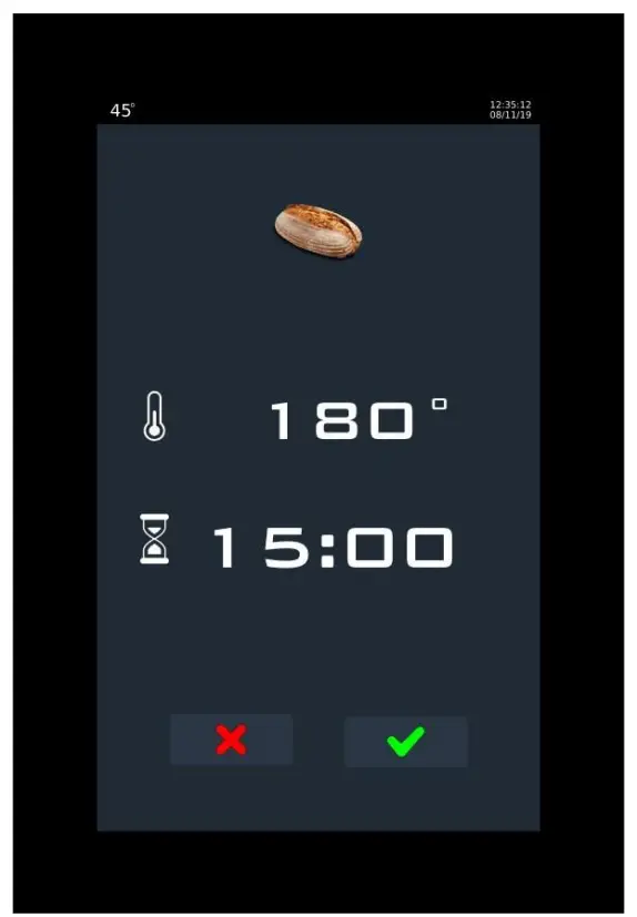
 | RECIPE NAME The recipe name can be changed by clicking here. |
 | RECIPE PHOTO |
 | TEMPERATURE |
| COOKING TIME | |
 | EXIT WIHTOUT SAVE THE RECIPE Exits without saving the recipe |
 | RECIPE SAVE BUTTON It saves the recipe |
RECIPE COOKING
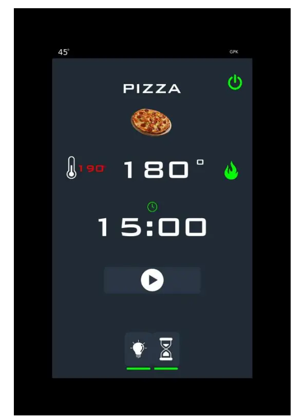
 | TEMPERATURE Oven temperature, set value and heaters status are shown here. If the heater icon is red, the heater output is passive, if the heater icon is green, the heater is active. |
 | COOKING TIME Cooking time can be set and started here. At the end of this period, the alarm is activated and the expiration warning is displayed on the screen. At the end of the time, the countdown can be continued with additional time if desired. |
| START / STOP BUTTON The oven cooking system is started and stopped with this button |
| TIME START BUTTON It is a time start and end button. |
CLEANING & MAINTENANCE
CLEANING AND MAINTENANCE AFTER EVERY USE
- Be sure that gas and electric connections are off before cleaning.
- Clean the inside of the oven with soft cloth by using oil solvent spray,before the appliance gets cooled exactly.
- Do not use abrasive cleaning chemicals as these can leave harmful residues.
- Do not use pressure water or vapor during the cleaning.
- Do not clean the appliance with the materials that may damage to chrome material.
PERIODIC CLEANING AND MAINTENANCE
- Maintenance should be done by qualified person.
- Get the periodic maintenance of the appliance once in every 15 days.
- Check the lighting lamp according to frequency of use.
- Check the cooking stones in periodic times. Change the broken and deformed stones.
- Check the gas connection hoses in periodic time. If there is slit,hole..etc, change the hoses.
- Ventilate the area where the appliance is in periodic times.
TROUBLESHOOTING
| THE APPLIANCE DOESN’T OPERATE |
| ||
| THE APPLIANCE DOESN’T COOK WELL |
| ||
| THE APPLIANCE STOPPED |
| ||
| RESET BUTTON LIGHT DOESN’T SIGNAL |
| ||
| LAMP IS NOT ON. |
| ||
| FAULT | EXPLANATION | NOTE | |
| E01 – CONNECTION FAULT | It is a malfunction related to the connection between the video card and the relay card. | Check the connection cable and its connections.. | |
| E02 – TC1 FAULT | Oven thermocouple failure. | Check the thermocouple and its connection. | |
| E06 – MEDIA SENSOR FAULT | There is a malfunction in the sensor measuring the ambient temperature | Check the ambient sensor on the card | |
| E07 – BURNER FAULT | Malfunction from burner is the signal. | Reset the burner. | |
- If cooking at pizza ovens (gas) is not done at suitable quality
- If any function of security doesn’t work
- Do not use the
*If these problems are still going on,contact with our authorized services.
INJECTOR CHANGE AND GAS SETTING
PIZZA OVENS (GAS ) BURNER-INJECTOR CHANGE CHART
| NG / LPG | GPOE430DN | GPOE630DN | GPOE930DN | |||||
| X | X | X | ||||||
| 2 | G20 | 3 | 1x | 3,5 | 1x | 3,5 | 1x | |
| G25 | 3 | 1x | 3,5 | 1x | 3,5 | 1x | ||
| 3 | G30 | 30 mbar | 2 | 1x | 2 | 1x | 2,5 | 1x |
| 50 mbar | 2 | 1x | 2 | 1x | 2,5 | 1x | ||
| G31 | 37 mbar | 2 | 1x | 2 | 1x | 2,5 | 1x | |
| 50 mbar | 2 | 1x | 2 | 1x | 2,5 | 1x | ||
Change of the burner injector
- The oven must be dispatched from the factory as it works with NG. The injectors of the ovens that will be worked with LPG must be changed by authorized service according to datas on the chart.
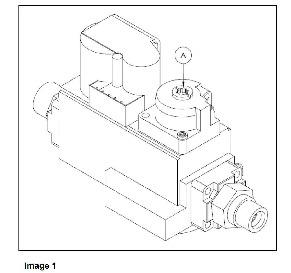
- Increase the gas by turning yellow part on the gas block. If it is turned (-) direction, the gas is reduced. (Image 1)
GAS CONNECTION IMAGES
SPARE PART LIST-EXPLODING DRAWING
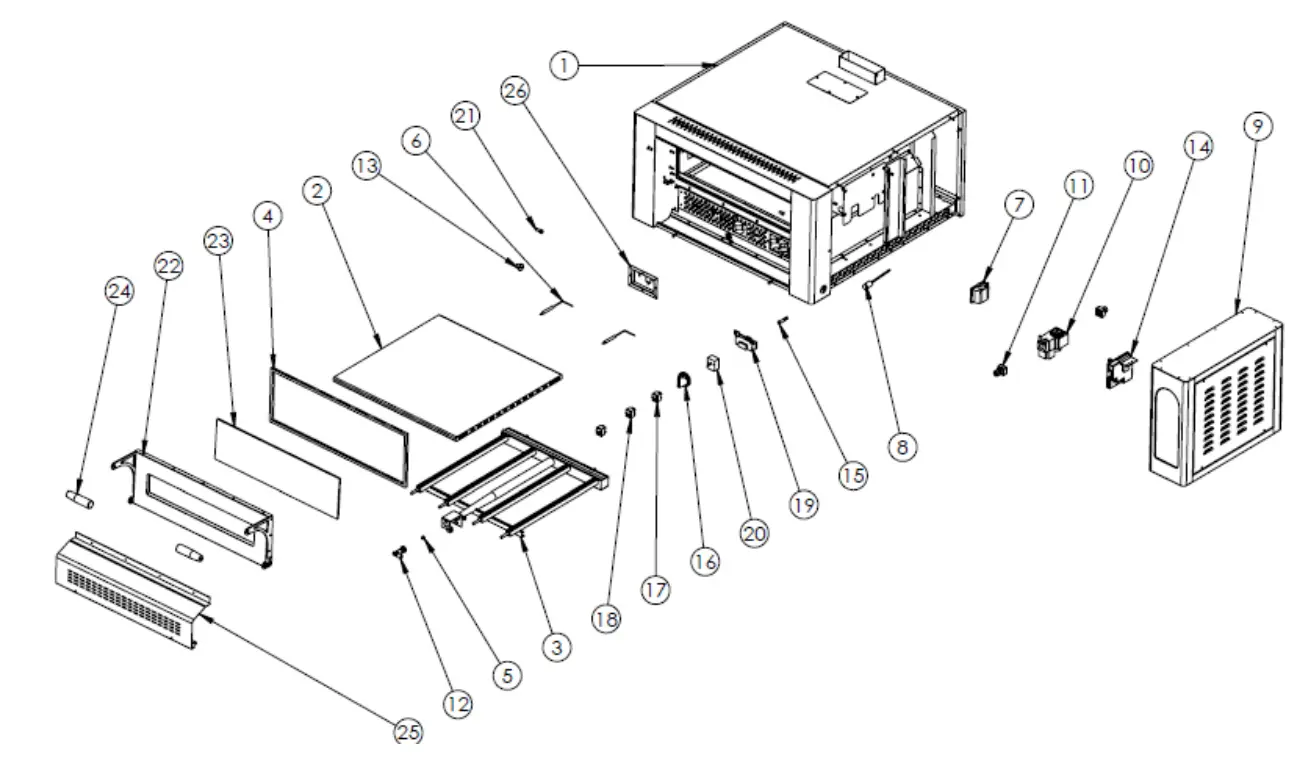
GPOE430DN
| PRODUCT CODE: GPOE430DN | ||
| NO | PRODUCT NAME | P.CODE |
| 1 | BASE FRAME | Y.GPOE430DN.001-R1 |
| 2 | PIZZA STONE | Y.GPOE430DN.002-R1 |
| 3 | BURNER | Y.GPOE430DN.003-R1 |
| 4 | WICK | Y.GPOE430DN.004-R1 |
| 5 | INJECTOR | Y.GPOE430DN.005-R1 |
| 6 | SPARKING PLUG+CABLE | Y.GPOE430DN.006-R1 |
| 7 | 25W LAMP | Y.GPOE430DN.007-R1 |
| 8 | THERMO PART | Y.GPOE430DN.008-R1 |
| 9 | ELECTRIC PANEL SHEETMETAL | Y.GPOE430DN.009-R1 |
| 10 | GAS BLOCK | Y.GPOE430DN.010-R1 |
| 11 | BLOCK CONNECTION PART | Y.GPOE430DN.011-R1 |
| 12 | BURNER BRACKET | Y.GPOE430DN.012-R1 |
| 13 | LID YELLOW RING | Y.GPOE430DN.013-R1 |
| 14 | FIRING CARD | Y.GPOE430DN.014-R1 |
| 15 | WARNING LAMP | Y.GPOE430DN.015-R1 |
| 16 | THERMOSTAT BUTTON | Y.GPOE430DN.016-R1 |
| 17 | SWITCH (ON-OFF) | Y.GPOE430DN.017-R1 |
| 18 | SWITCH (RESET) | Y.GPOE430DN.018-R1 |
| 19 | ANALOG INDICATOR | Y.GPOE430DN.019-R1 |
| 20 | THERMOSTAT 50-450 | Y.GPOE430DN.020-R1 |
| 21 | LID CONNECTION SCREW M8 | Y.GPOE430DN.021-R1 |
| 22 | LID | Y.GPOE430DN.022-R1 |
| 23 | GLASS | Y.GPOE430DN.023-R1 |
| 24 | HANDLE | Y.GPOE430DN.024-R1 |
| 25 | FRONT AIR CONDITIONING SHEETMETAL | Y.GPOE430DN.025-R1 |
| 26 | SPARKING PLUG SHEETMETAL | Y.GPOE430DN.026-R1 |
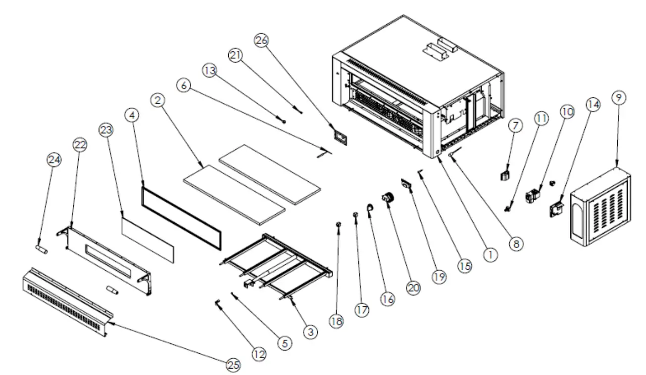
GPOE630DN
| PRODUCT CODE: GPOE630DN | ||
| NO | PRODUCT NAME | P.CODE |
| 1 | BASE FRAME | Y.GPOE630DN.001-R1 |
| 2 | PIZZA STONE | Y.GPOE630DN.002-R1 |
| 3 | BURNER | Y.GPOE630DN.003-R1 |
| 4 | WICK | Y.GPOE630DN.004-R1 |
| 5 | INJECTOR | Y.GPOE630DN.005-R1 |
| 6 | SPARKING PLUG+CABLE | Y.GPOE630DN.006-R1 |
| 7 | 25W LAMP | Y.GPOE630DN.007-R1 |
| 8 | THERMO PART | Y.GPOE630DN.008-R1 |
| 9 | ELECTRIC PANEL SHEETMETAL | Y.GPOE630DN.009-R1 |
| 10 | GAS BLOCK | Y.GPOE630DN.010-R1 |
| 11 | BLOCK CONNECTION PART | Y.GPOE630DN.011-R1 |
| 12 | BURNER BRACKET | Y.GPOE630DN.012-R1 |
| 13 | LID YELLOW RING | Y.GPOE630DN.013-R1 |
| 14 | FIRING CARD | Y.GPOE630DN.014-R1 |
| 15 | WARNING LAMP | Y.GPOE630DN.015-R1 |
| 16 | THERMOSTAT BUTTON | Y.GPOE630DN.016-R1 |
| 17 | SWITCH (ON-OFF) | Y.GPOE630DN.017-R1 |
| 18 | SWITCH (RESET) | Y.GPOE630DN.018-R1 |
| 19 | ANALOG INDICATOR | Y.GPOE630DN.019-R1 |
| 20 | THERMOSTAT 50-450 | Y.GPOE630DN.020-R1 |
| 21 | LID CONNECTION SCREW M8 | Y.GPOE630DN.021-R1 |
| 22 | LID | Y.GPOE630DN.022-R1 |
| 23 | GLASS | Y.GPOE630DN.023-R1 |
| 24 | HANDLE | Y.GPOE630DN.024-R1 |
| 25 | FRONT AIR CONDITIONING SHEETMETAL | Y.GPOE630DN.025-R1 |
| 26 | SPARKING PLUG SHEETMETAL | Y.GPOE630DN.026-R1 |
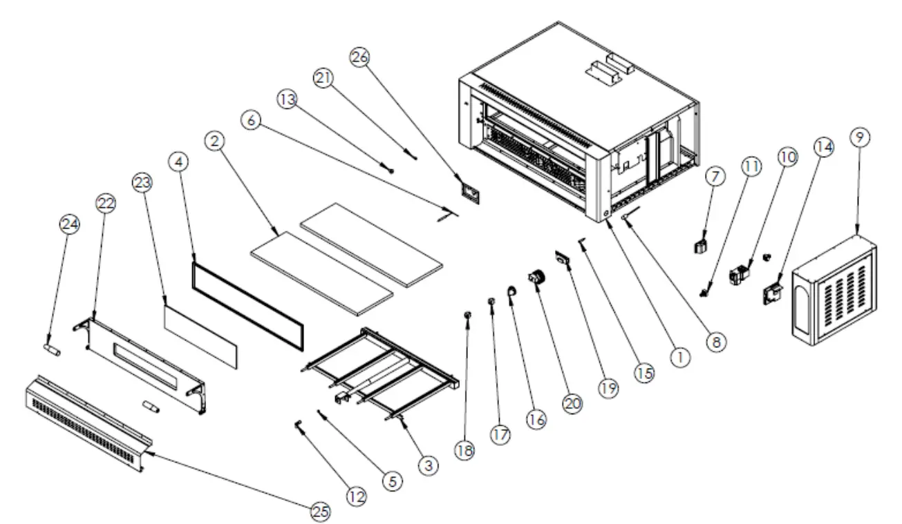
GPOE930DN
| PRODUCT CODE: GPOE930DN | ||
| NO | PRODUCT NAME | P.CODE |
| 1 | BASE FRAME | Y.GPOE930DN.001-R1 |
| 2 | PIZZA STONE | Y.GPOE930DN.002-R1 |
| 3 | BURNER | Y.GPOE930DN.003-R1 |
| 4 | WICK | Y.GPOE930DN.004-R1 |
| 5 | INJECTOR | Y.GPOE930DN.005-R1 |
| 6 | SPARKING PLUG+CABLE | Y.GPOE930DN.006-R1 |
| 7 | 25W LAMP | Y.GPOE930DN.007-R1 |
| 8 | THERMO PART | Y.GPOE930DN.008-R1 |
| 9 | ELECTRIC PANEL SHEETMETAL | Y.GPOE930DN.009-R1 |
| 10 | GAS BLOCK | Y.GPOE930DN.010-R1 |
| 11 | BLOCK CONNECTION PART | Y.GPOE930DN.011-R1 |
| 12 | BURNER BRACKET | Y.GPOE930DN.012-R1 |
| 13 | LID YELLOW RING | Y.GPOE930DN.013-R1 |
| 14 | FIRING CARD | Y.GPOE930DN.014-R1 |
| 15 | WARNING LAMP | Y.GPOE930DN.015-R1 |
| 16 | THERMOSTAT BUTTON | Y.GPOE930DN.016-R1 |
| 17 | SWITCH (ON-OFF) | Y.GPOE930DN.017-R1 |
| 18 | SWITCH (RESET) | Y.GPOE930DN.018-R1 |
| 19 | ANALOG INDICATOR | Y.GPOE930DN.019-R1 |
| 20 | THERMOSTAT 50-450 | Y.GPOE930DN.020-R1 |
| 21 | LID CONNECTION SCREW M8 | Y.GPOE930DN.021-R1 |
| 22 | LID | Y.GPOE930DN.022-R1 |
| 23 | GLASS | Y.GPOE930DN.023-R1 |
| 24 | HANDLE | Y.GPOE930DN.024-R1 |
| 25 | FRONT AIR CONDITIONING SHEETMETAL | Y.GPOE930DN.025-R1 |
| 26 | SPARKING PLUG SHEETMETAL | Y.GPOE930DN.026-R1 |
ELECTRIC CIRCUIT SCHEMA
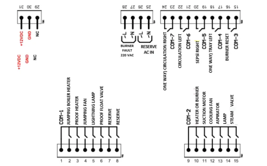
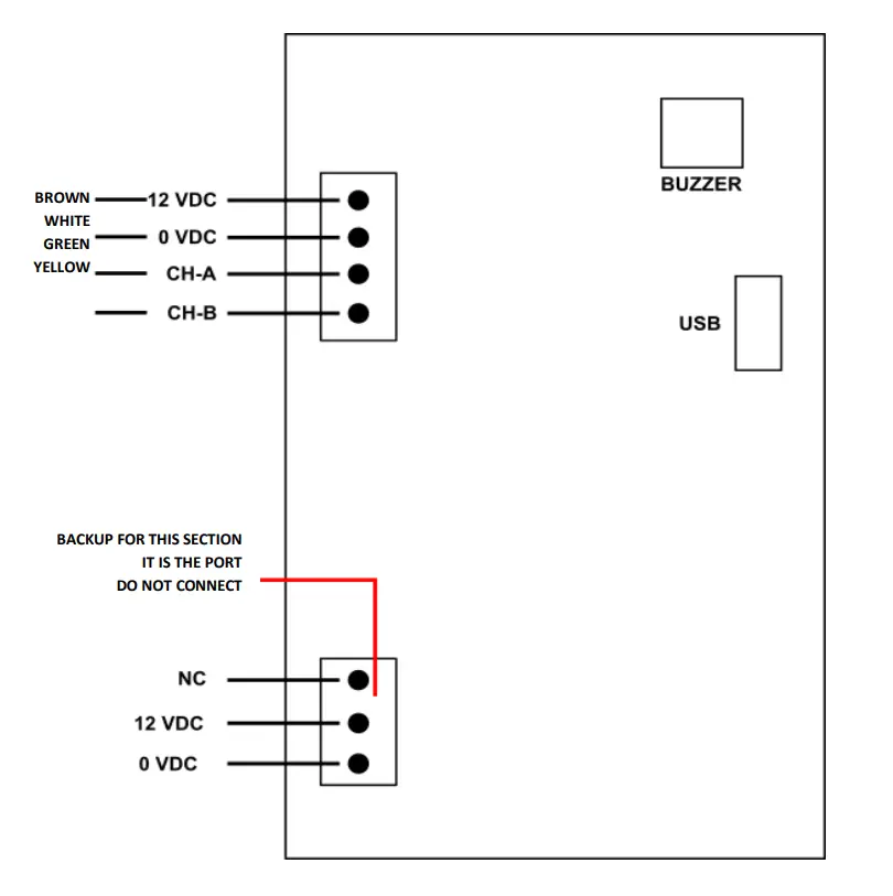
TOP CARD
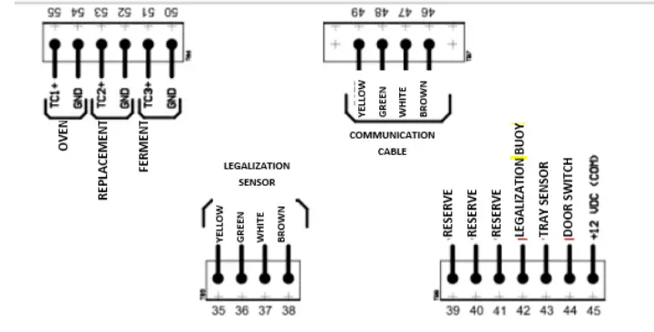
PANNEL CONNECTION