
![]() ViewBoard IFP70 Series Commercial Touch Display
ViewBoard IFP70 Series Commercial Touch Display
User Guide
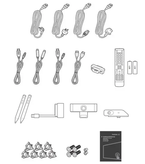
Package Contents
| • Power cable (Ship by region) | • RS232 adapter | • Camera |
| • USB cable (3m) | • Remote control | • Sensor hub |
| • USB type-c cable (1.5m) | • AAA battery x 2 | • Clamp x 7 |
| • Camera USB cable (2m) | • Smart pen | • Screw x 6 |
| • HDMI cable (3m) | • Smart pen charger & receiver | • Quick start guide |
 Wall Mount Kit Specification
 Wall Mount Kit Specification
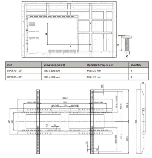
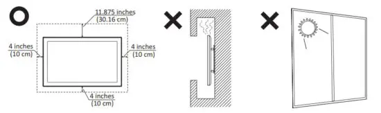
Installation Environment Attention
Control Panel Overview
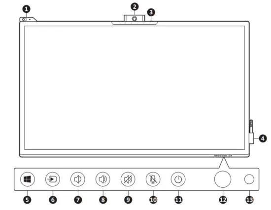
| Item | Description |
| 1 | Sensor hub to monitor temperature, humidity, luminosity, and PIR (motion sensor). |
| 2 | Camera |
| 3 | Microphone |
| 4 | Smart Pen and Charger |
| 5 | Windows button |
| 6 | Source select |
| 7 | Decrease the Volume |
| 8 | Increase the Volume |
| 9 | Speaker Mute |
| 10 | Microphone Mute |
| 11 | Turn on/off the device Tap to enter Energy Saving mode Press and hold for at least two (2) seconds to enter Standby mode |
| 12 | Remote control receiver |
| 13 | ODPower indicator light |
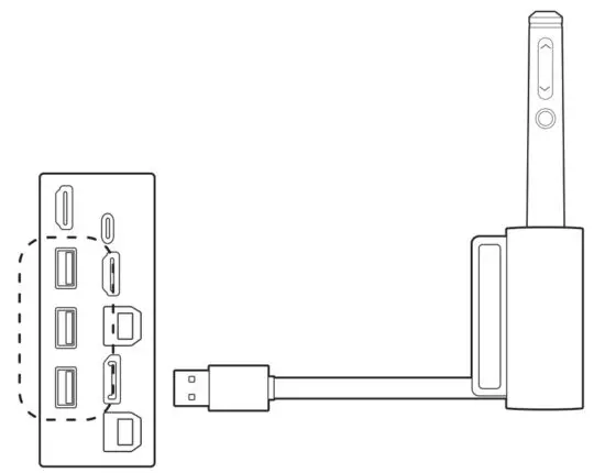
Terminal Interface Overview
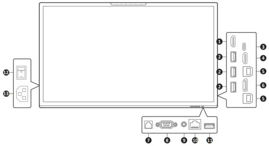
| Item | Description | |
| 1 | HDMI OUT | Connect to devices with HDMI input function. |
| 2 | USB 3.0 | Connect USB devices such as hard disks, keyboards, mice, etc. |
| 3 | USB Type C | Charging support up to 60W, OTG, Data transmission, network signal output, and Extension for Audio and Video output. |
| 4 | HDMI IN | High definition input; connect to PC with HDMI output, set-top box, or another video device. |
| 5 | TOUCH | Touch signal output to external PC. Network signal out to external PC when Embedded Player has Lan port input. After connection (with an external PC), the external PC’s audio can be played through the ViewBoard, and the external PC’s audio can be controlled by the audio button of the ViewBoard. After connection (with an external PC), the device connected to the USB 3.0 port can be directly used by an external PC. |
| 6 | DisplayPort | Connect to devices with DisplayPort output function. |
| 7 | SPDIF | Multichannel sound via optical signals. |
| 8 | RS232 | Serial interface; used for mutual transfer of data between devices. |
| 9 | AUDIO OUT | Audio output to an external speaker. |
| 10 | LAN | Standard R.145 (10M/100M/1G) Internet connection interface (This network port is used for Embedded Player and Slot in PC). |
| 11 | USB 2.0 | Connect USB devices such as hard disks, keyboards, mice, etc. |
| 12 | AC Switch | Turn on/off AC power supply “I” = Power on, “0” = Power off |
| 13 | AC IN | AC power input |
 The terms HDMI and HDMI High-Definition Multimedia Interface, and the HDMI Logo are trademarks or registered trademarks of HDMI Licensing LLC in the United States and other countries.
Smart Pen and Charger
Charger
The charger is magnetically attached to the lower right side of the ViewBoard. Connect the charger to the USB 3.0 port on the side of the panel.
Button Function of the Smart Pen
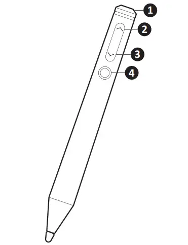
| Item | Description |
| 1 | Eraser |
| 2 | Previous Page |
| 3 | Next Page |
| 4 | Laser Pointer |
Note: After the charger has been connected to the ViewBoard, the button functions of the Smart Pen can be used.
Pairing/Unpairing
To pair/unpair the Smart Pen with the ViewBoard:
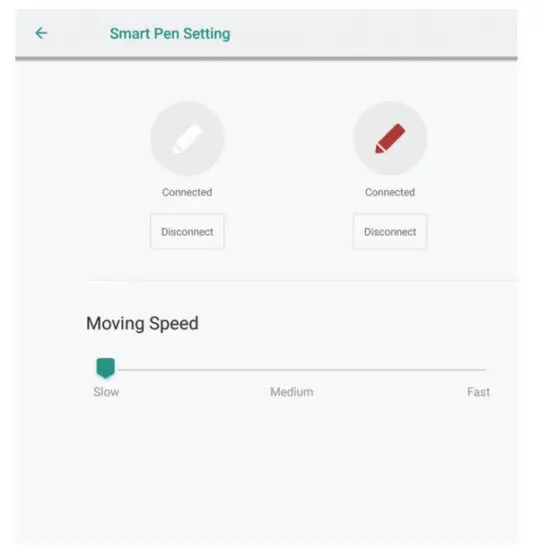
- Go to: Settings > Personal > Smart Pen Setting.
- To Pair: Press the 2 and 4 button on the Smart Pen at the same lime. The LED indicator will go from solid white to flashing orange, and finally off when paired.
- To Unpair: Press the 3 and 4 button on the Smart Pen at the same time. The LED indicator will go from flashing orange to solid white, and finally off when unpaired.
Note: The connection status and moving speed can be viewed and adjusted as well.
Charging
As shown below, the Smart Pen will charge automatically by inserting it into the charger that is connected to the ViewBoard.
Note: Two (2) hours of charge will yield eight (8) hours of Smart Pen use.
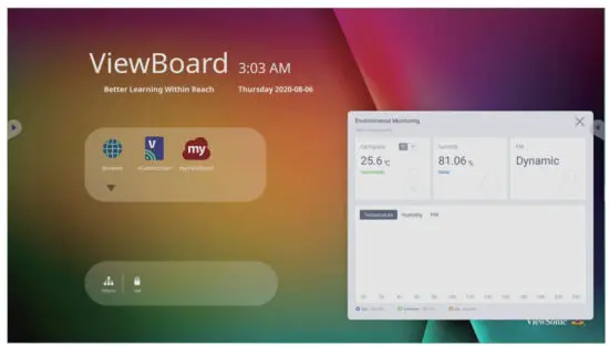
Sensor Hub
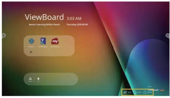
Once installed, and WCD mode is activated, the sensor hub will collect environmental data (Temperature, Humidity, Lumionsity, and PIR) and display it on-screen.
To install the sensor hub:
- Insert the prongs on the bottom of the sensor into the top, upper left of the ViewBoard.
- Secure the sensor with the additional two screws.
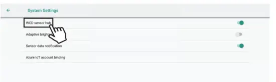
WCD Mode
When activated, WCD mode will display the environmental data (Temperature, Humidity, Lumionsity, and PIR) supplied by the sensor hub on-screen.
To activate WCD mode:
- Go to: Settings > System > System Settings.
- Select WCD to toggle WCD mode On or Off.

- When WCD mode is turned on, the environmental data will be displayed on-screen.

- Touching the environmental data will launch a more detailed overview of the collected data.

Note: When powered off/the backlight is off (standby mode), if the PIR sensors detect movement after standing by for 20 seconds it will turn on automatically.
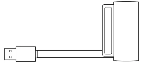
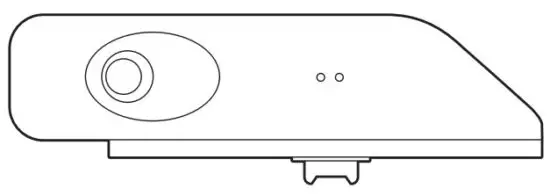
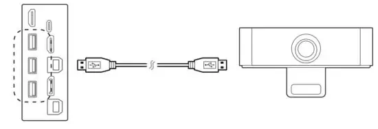
Camera
The camera is magnetically attached to the top middle of the ViewBoard. Connect the camera to the USB 3.0 port on the side of the panel as shown below.
Note: A USB cable of at least two (2) meters should be used.
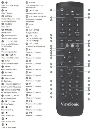
Remote Control Overview
Connecting External Devices and Touch Connection
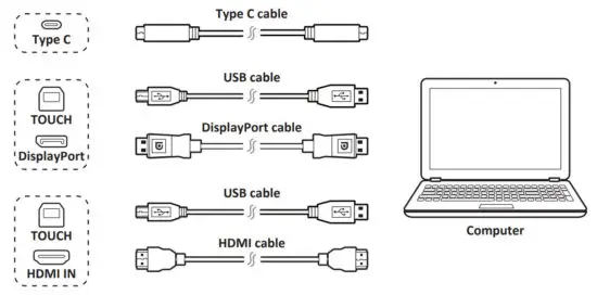
Your external device(s) can be connected in any of the following configurations:
Type C Connection
Connect a Type C cable from your external device to the Type C port on the ViewBoard.
DisplayPort Connection
- Connect a DisplayPort cable from your external device to the DisplayPort port on the ViewBoard.
- Connect a USB cable to the external device from the TOUCH port of the ViewBoard.
HDMI Connection
- Connect an HDMI cable from your external device to the HDMI IN port on the ViewBoard.
- Connect a USB cable to the external device from the TOUCH port of the ViewBoard.
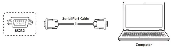
RS232 Connections
When you use a RS232 serial port cable to connect your display to an external computer certain func-tions can be controlled remotely by the PC, including Power On/Off, Volume adjustment, Input select, Brightness, and more.
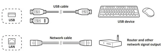
USB and Networking Connections
Just like any PC, it is easy to connect various USB devices and other peripherals to your ViewBoard.
USB Peripherals
Plug the USB device cable into the USB port.
Networking and Modem cables
Plug the router cable into the LAN port.
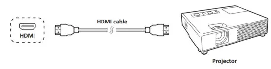
Media Player (Audio and Video) Connection
To connect to a media player:
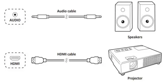
- Connect the HDMI cable to the HDMI ports on your ViewBoard and peripheral device.
- Plug in the power cord of your ViewBoard, and turn on the rear-panel power supply switch.
- Press the Power button on the right-hand side of the ViewBoard to turn the screen on.
- Press the INPUT button on the remote control and switch to the “HDMI” input source.
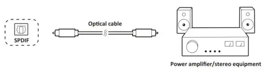
SPDIF Connection
To connect to an external sound system:
- Connect an optical cable from the SPDIF port to your sound system’s optical connector.
- Plug in the power cord of your ViewBoard, and turn on the rear-panel power supply switch.
- Press the Power button on the right-hand side of the ViewBoard to turn the screen on.
Note: S/PDIF & Earphone audio output are working on Embd Player, HDMI, and DP channel only.
Video Output Connection
To output video via a display device:
- Connect an HDMI cable to the HDMI IN port of your display device, and the other end to the HDMI OUT port of your ViewBoard.
- For audio, connect one end of an audio cable to your ViewBoard’s AUDIO OUT port and the other end to your speakers.
- Plug in the power cord of your ViewBoard, and turn on the rear-panel power supply switch.
- Press the Power button on the right-hand side of the ViewBoard to turn the screen on.
Note: S/PDIF & Earphone audio output are working on Embd Player, HDMI, and DP channel only.
Annotation(Overlay digital pens)
Tool bar tigger icons are on the edge of the ViewBoard laucher
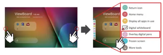
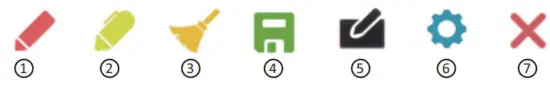
| Item | Description |
| Access the pen, highlighter, clear, and save options
|
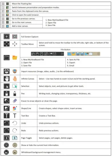
myViewBoard Software
Floating Bar
vCastReceiver & vCastSender Service
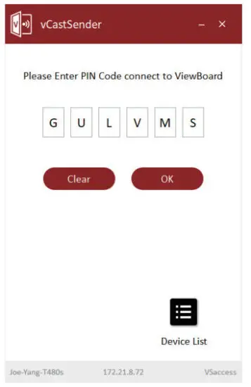
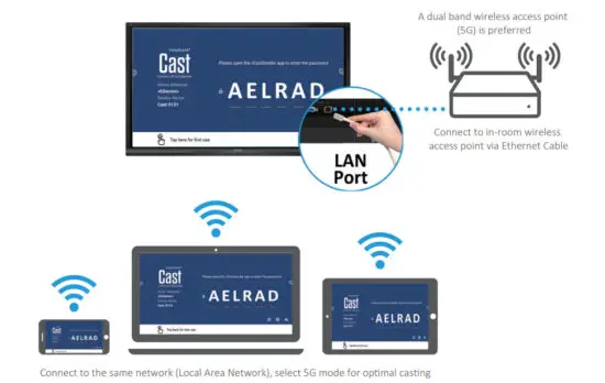
Working with ViewBoard® Cast software, the vCastReceiver app, will allow ViewBoard® to receive vCastSender laptop screens (Windows/Mac/Chrome) and mobile ( i0S/Android) users’ screens, photos, videos, annotations, and camera(s). It is also compatible with Apple AirPlay®.
Network information
- ViewBoard® Cast software, laptops, and mobile devices can connect to both the same subnet and across the subnet
- Please enter the on-screen PIN-code to connect to the
- Ports :
– TCP 56789, 25123, 8121 & 8000
– UDP 48689, 25123 - Port and DNS for activation:
– Port: 443
– DNS: https://vcastactivate.viewsonic.com - OTA service:
– Server Port: TCP443
– Server FQDN Name: https://vcastupdate.viewsonic.com
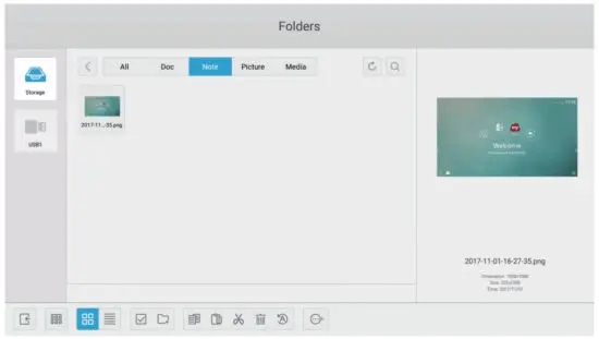
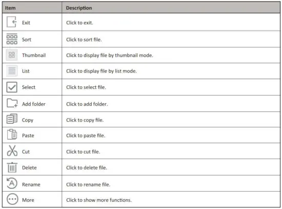
vCastReceiver
Folders
Compliance Statement
FCC Compliance Statement:
FCC Compliance Statement: This device complies with part 15 of FCC Rules. Operation is subject to the following two conditions: (1) this device may not cause harmful interference, and (2) this device must accept any interference received, including interference that may cause undesired operation.
Industry Canada ICES-003 Compliance: CAN ICES-3 (B)/NMB-3(B)
![]() ViewSonic Corporation (US/Canada/Latin America)
ViewSonic Corporation (US/Canada/Latin America)![]() : www.viewsonic.com/support/product-registration
: www.viewsonic.com/support/product-registration
![]() United States
United States![]() 1-800-688-6688
1-800-688-6688![]() [email protected]
[email protected]
Canada![]() 1-866-463-4775
1-866-463-4775![]() [email protected]
[email protected]
Puerto Rico & Virgin Islands![]() http://www.viewsonic.com/la/soporte/servicio-tecnico (Espanol)
http://www.viewsonic.com/la/soporte/servicio-tecnico (Espanol)
Latin America![]() http://www.viewsonic.com/la/soporte/servicio-tecnico-la/
http://www.viewsonic.com/la/soporte/servicio-tecnico-la/


