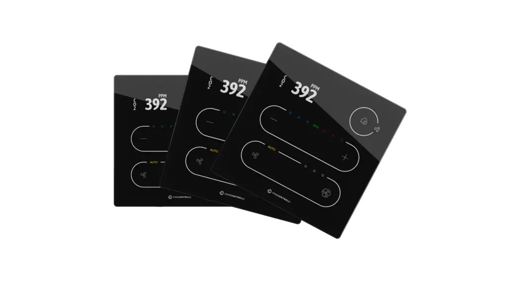
![]() TP Modern Comfort Management Wall Panel
TP Modern Comfort Management Wall Panel
User Manual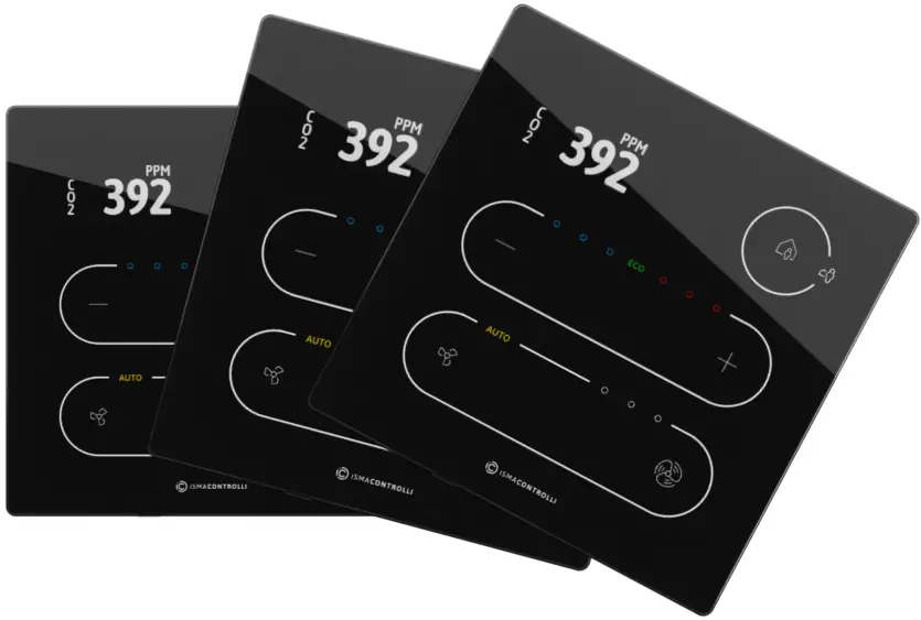
Introduction
The TP TouchPoint is a modern comfort management wall panel with the two most popular open communication protocols: Modbus RTU/ASCII and BACnet MS/TP. The TouchPoint is available in different configurations of sensors (temperature, CO2, and humidity), colors, and versions with or without a display. The panel is equipped with an interactive TFT touchscreen, touch buttons, and a glass panel.
The panel can be configured using the ISMA Configurator software or Modbus registers/BACnet objects. It fits most of the standard junction boxes in Europe and can easily be installed using a wall back box.
Revision History
Table 1. Revision history
| Rev | Date | Description |
| 1.0 | 20 Apr 2022 | First edition |
Safety Rules
- Improper wiring of the product can damage it and lead to other hazards. Make sure that the product has been correctly wired before turning the power on.
- Before wiring or removing/mounting the product, make sure to turn the power off. Failure to do so might cause an electric shock.
- Do not touch electrically charged parts such as power terminals. Doing so might cause an electric shock.
- Do not disassemble the product. Doing so might cause an electric shock or faulty operation.
- Use the product only within the operating ranges recommended in the specification (temperature, humidity, voltage, shock, mounting direction, atmosphere, etc.). Failure to do so might cause a fire or a faulty operation.
- Firmly tighten the wires to the terminal. Failure to do so might cause a fire.
- Avoid installing the product in close proximity to high-power electrical devices and cables, inductive loads, and switching devices. The proximity of such objects may cause an uncontrolled interference, resulting in an unstable operation of the product.
- Proper arrangement of the power and signal cabling affects the operation of the entire control system. Avoid laying the power and signal wiring in parallel cable trays. It can cause interferences in monitored and controlled signals.
- It is recommended to power controllers/modules with AC/DC power suppliers. They provide better and more stable insulation for devices compared to AC/AC transformer systems, which transmit disturbances and transient phenomena like surges and bursts to devices. They also isolate products from inductive phenomena from other transformers and loads.
- Power supply systems for the product should be protected by external devices limiting overvoltage and effects of lightning discharges.
- Avoid powering the product and its controlled/monitored devices, especially high power and inductive loads, from a single power source. Powering devices from a single power source causes a risk of introducing disturbances from the loads to the control devices.
- If an AC/AC transformer is used to supply control devices, it is strongly recommended to use a maximum 100 VA Class 2 transformer to avoid unwanted inductive effects, which are dangerous for devices.
- Long monitoring and control lines may cause loops in connection with the shared power supply, causing disturbances in the operation of devices, including external communication. It is recommended to use galvanic separators.
- To protect signal and communication lines against external electromagnetic interferences, use properly grounded shielded cables and ferrite beads.
- Switching the digital output relays of large (exceeding specification) inductive loads can cause interference pulses to the electronics installed inside the product. Therefore, it is recommended to use external relays/contactors, etc. to switch such loads. The use of controllers with Triac outputs also limits similar overvoltage phenomena.
Technical Specification
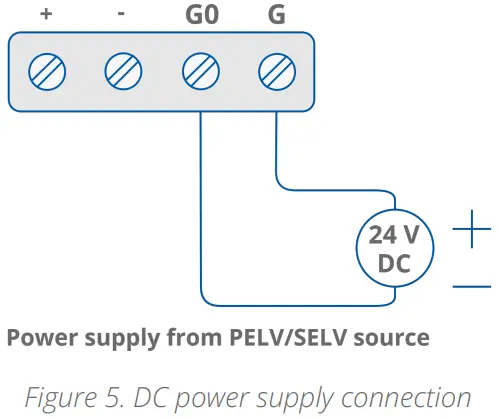
| Power Supply | DC | 20-34 V |
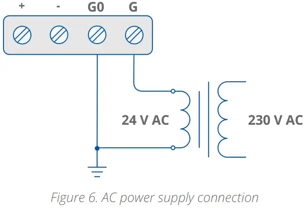
| AC | 24 V ± 20% | |
| Built-in Sensors | Temperature sensor | 10k NTC type, accuracy: ± 0.5˚C, resolution: ± 0.1˚C |
| Humidity sensor (applies to the version with humidity sensor) | Range: 0-100% RH, accuracy: ± 2% RH in range 10-90% RH, resolution: ± 0.1˚C | |
| CO2 sensor (applies to the version with CO2 sensor) | Range: 400-4000 ppm, accuracy: ± 30 ppm | |
| COM1 | RS485 interface | Up to 128 devices |
| Half-duplex | ||
| Communication protocols | Modbus RTU/ASCII, BACnet MS/TP | |
| Ports | 2 RJ45, screw connector | |
| Baud rate | 4800-115200 | |
| Power supply | 30 V | |
| Front Panel | Surface | White/black glass |
| Display (applies to the version with display) | TFT 0.96″ | |
| Backlight | 3 intensity modes | |
| Buttons | 5 | |
| LED | 3 blue and 3 red for temperature | |
| 3 white for fan | ||
| 1 white for occupancy | ||
| 1 configurable RGB | ||
| Ingress Protection | IP rating | IP20 for indoor installation |
| Temperature | Operating | From 0°C to +40°C |
| Storage | From -40°C to +70°C | |
| Humidity | Relative | From 5% to 95% RH (without condensation) |
| Screw Connector | Type | Removable screw terminals |
| Maximum cable size | 1.5 mm2 (24…16 AWG) | |
| Housing | Material | Plastic, self-extinguishing ABS |
| Mounting | Standard 60 mm wall back box | |
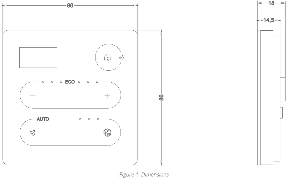
| Dimensions | Metric | 86x86x14.5 mm |
| Inches | 3.39×3.39×0.57 in | |
Table 2. Technical specification | ||
Hardware Specification
This section outlines all details regarding the hardware specification of the TP panel.
Panel Versions
The TP panel is available in the following versions:
| Product Code | Temperature Sensor | CO2 Sensor | Humidity Sensor | Display | Color | |
| Black | White | |||||
| TP-DISP-B | ||||||
| TP-H-DISP-B | ||||||
| TP-C-DISP-B | ||||||
| TP-HC-DISP-B | ||||||
| TP-DISP-W | ||||||
| TP-H-DISP-W | ||||||
| TP-C-DISP-W | ||||||
| TP-HC-DISP-W | ||||||
| TP-B | ||||||
| TP-H-B | ||||||
| TP-C-B | ||||||
| TP-HC-B | ||||||
| TP-W | ||||||
| TP-H-W | ||||||
| TP-C-W | ||||||
| TP-HC-W | ||||||
Table 3. Panel versions
- DISP: display (product code without a DISP part means a panel without a display);
- C: CO2 sensor (optional);
- H: humidity sensor (optional)
Note: All panels are available in black or white, which is reflected in the last letter of the product code, e.g., TP-H-DISP-B or TP-C-W.
Dimensions
Touchscreen
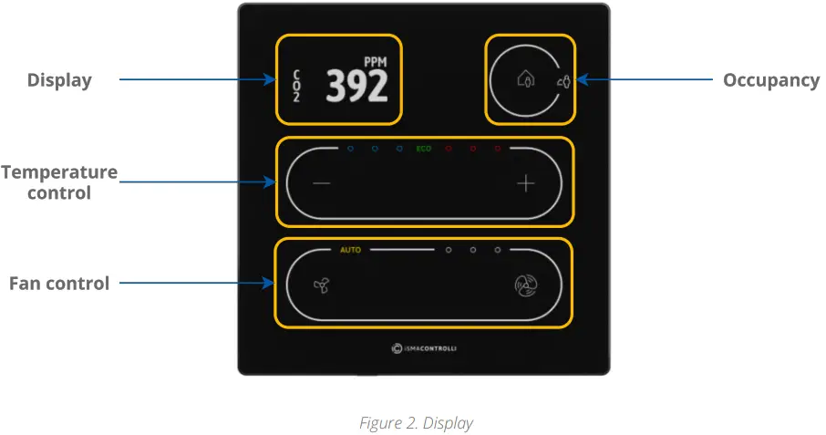
- 5 buttons for occupancy, temperature (–/+), and fan (small fan/big fan icons) control;
- 3 blue and 3 red LEDs for temperature signalization;
- 3 white LEDs for fan signalization.
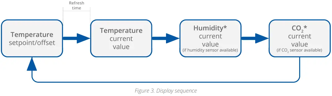
The LCD display shows the following information:
- temperature setpoint or offset (after pushing a + or – button, according to configuration);
- temperature current value with the unit;
- humidity current value with the unit (optionally);
- CO2 current value with the unit (optionally).
Note: Currently displayed parameters change with a frequency set in the 40217 registers.
4.3.1 LEDs
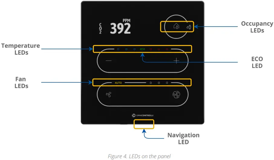
The panel is equipped with:
- 1 white LED for signalizing occupancy status;
- 3 blue and 3 red LEDs for temperature signalization (cooling or heating);
- 3 white LEDs for fan modes indication;
- 1 ECO LED;
- 1 navigation LED to localize the panel in the dark.
4.3.2 LED Modes
The TP panel works in 3 modes of LED lighting intensity:
- active: the LED lighting mode after any button on the screen has been touched;
- idle: the LED lighting mode after a time set from the last button has been touched;
- standby: the LED lighting mode after a time set from going into the idle mode.
All lighting intensity values in these three different modes can be set in the 40207-40216 Modbus registers.
Buzzer
The TP panel is equipped with a buzzer, which informs about a detected touch with a short sound.
The buzzer also provides a CO2 alarm function, which emits sounds once the CO2 level exceeds a set alarm value. The alarm can be confirmed and muted by pressing any button.
The buzzer may be activated or deactivated using the DEVICE_CONFIGURATION register/object (bit 0, BUZZER).
| Register Value | Description |
| 0 | Buzzer deactivated |
| 1 | Buzzer activated |
Table 4. The BUZZER values
Power Supply
4.5.1 DC Power Supply Connection
4.5.2 AC Power Supply Connection
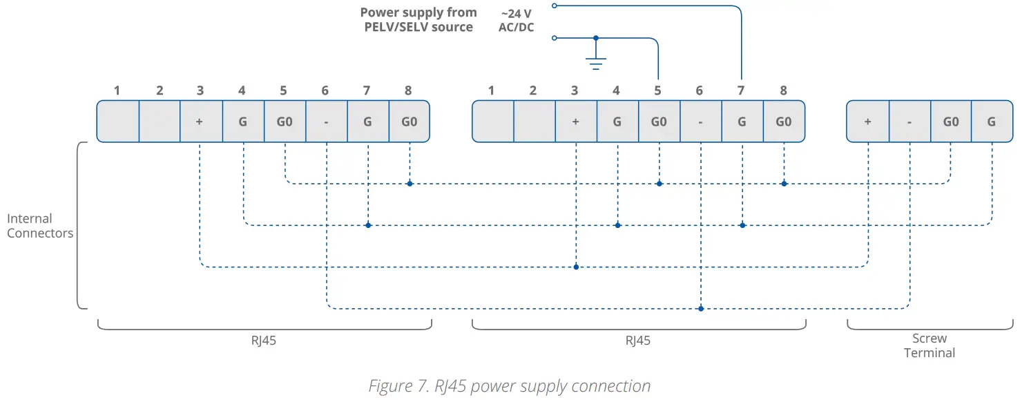
4.5.3 RJ45 Power Supply Connection
Communication
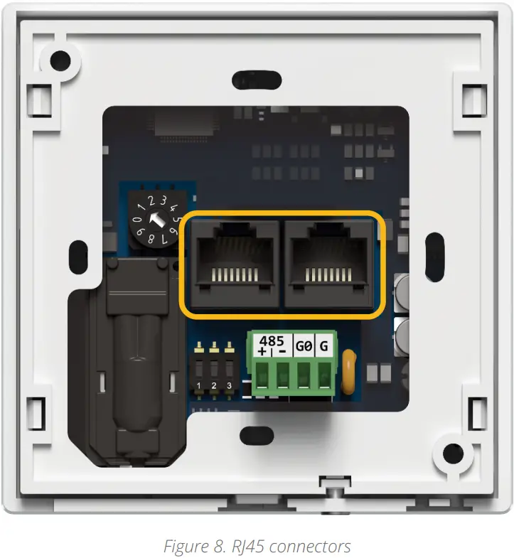
The TP panel supports Modbus RTU/ASCII and BACnet MS/TP communication protocols, using 2 RJ45 sockets and a screw terminal. The panel has one USB type C (USB 2.0) port for communication with the ISMA Configurator and FCU Updater software.
Note: A communication protocol is selected by setting a second switch on the DIP switch on the back of the panel:
- Off: Modbus RTU/ASCII (default);
- On: BACnet MS/TP.
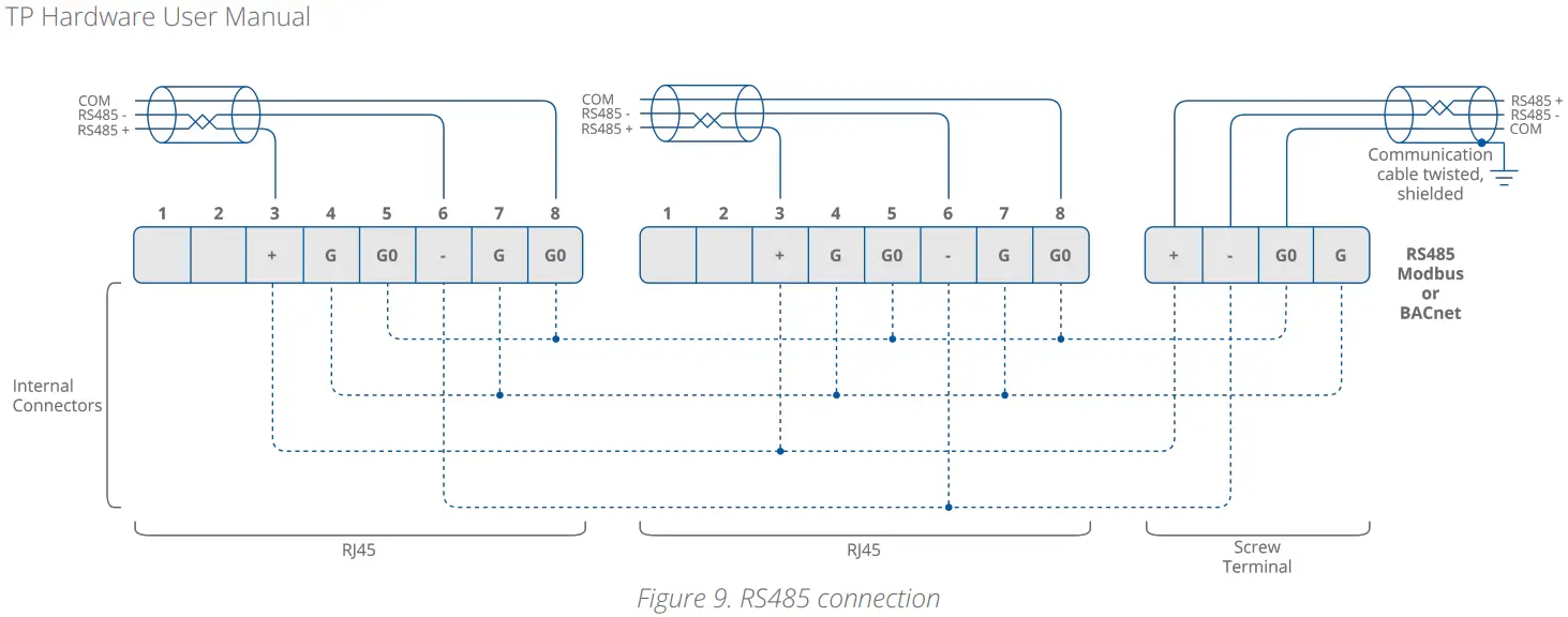
4.6.1 RS485 Connection
4.6.2 RS485 Network Termination
Transmission line effects often present a problem for data communication networks.
These problems include reflections and signal attenuation. To eliminate the presence of reflections of signal from the end of the cable, the cable must be terminated at both ends with a resistor across the line adequate to its characteristic impedance. Both ends must be terminated since the propagation is bidirectional. In the case of an RS485 twisted pair cable, this termination is typically 120 Ω.
Note: A termination resistor can be added with a third switch on the DIP switch on the back of the panel:
- Off: termination resistor disconnected (default);
- On: termination resistor added.
4.6.3 USB Connection
The USB port is used to communicate with product software, such as the iSMA Configurator or FCU Updater, for configuration and firmware updates. The USB port
provides a 5 V DC power supply.
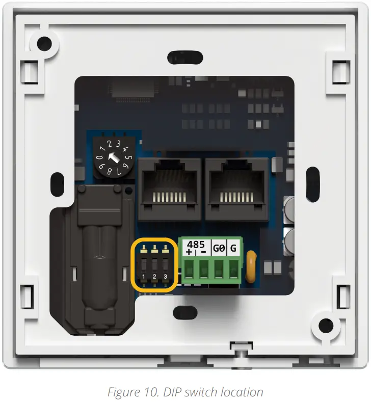
DIP Switch
The TP panel is equipped with a 3-position DIP switch. Each of the three sections has a separate function:
- the first switch allows for restoring default settings;
- the second switch allows for selecting a communication protocol;
- and the third switch allows for the RS485 network termination.
4.7.1 Restoring Default Settings
The first switch provides a possibility to restore default settings in the panel. In order to do so, follow the steps below
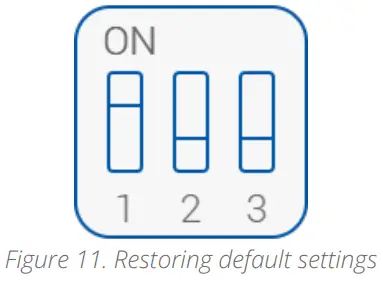
- Turn off the power supply;
- Set the first switch to on;
- Turn on the power supply;
- Wait until the display blinks;
- Set the third switch off.
Default Settings
| Variable | Default Value |
| Baud rate | 115200 |
| Stop bits | 1 |
| Data bits | 8 |
| Parity bits | None |
| Protocol | Modbus RTU |
| Modbus address | 1 |
| Replay delay | None |
| Table 5. Default values | |
4.7.2 Selecting Communication Protocol
The second switch selects between the available communication protocols, Modbus RTU/ASCII or BACnet MS/TP:
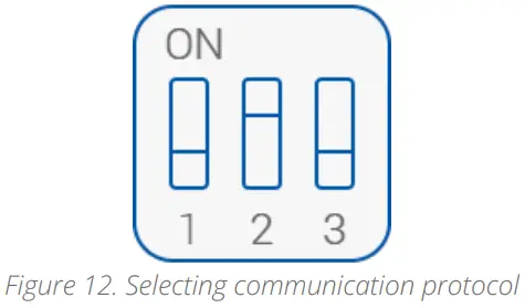
- Off: Modbus RTU/ASCII (default);
- On: BACnet MS/TP.
4.7.3 RS485 Network Termination
The third switch adds or disconnects a termination resistor to the RS485 network:
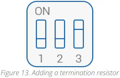
- Off: termination resistor disconnected (default);
- On: termination resistor added (120 Ω).
Rotary Switch
4.8.1 Setting Device Address
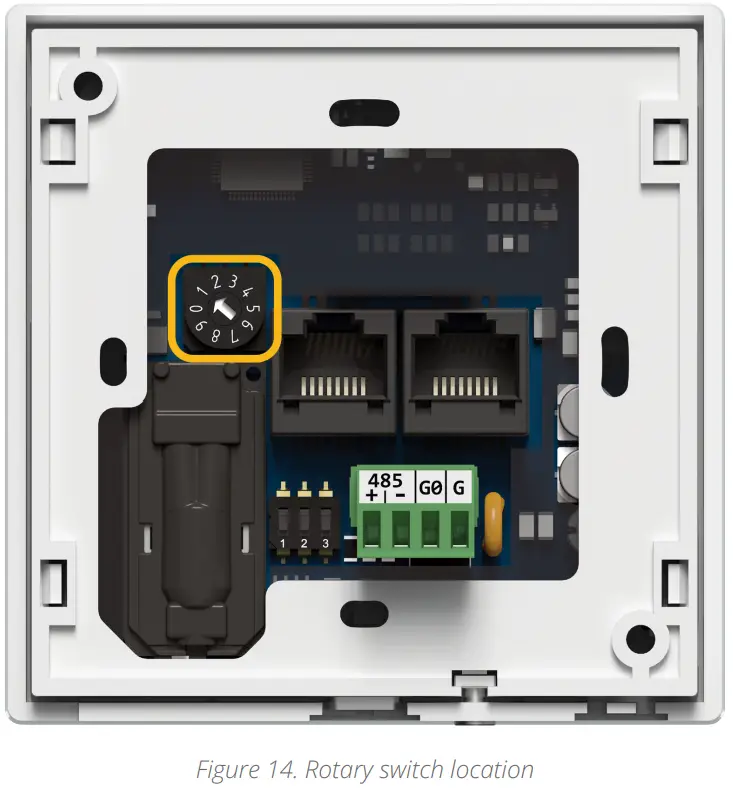
The TP panel is equipped with a rotary switch, which allows for setting a Modbus address in a range from 0 to 9. If the switch is set to 0, the address is read from the ADDRESS register/object (decimal address: 22).
Mounting and Installation
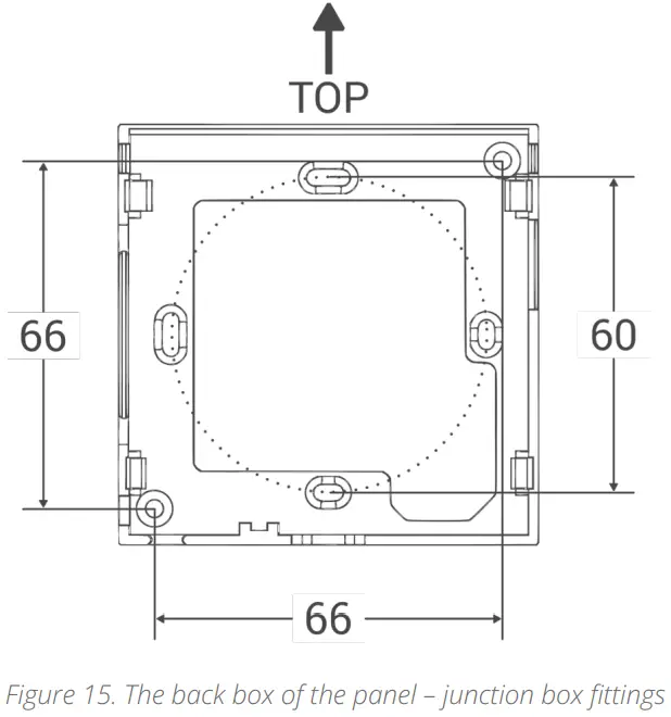
Step 1: Fit the back box to the junction box.
Step 2: Fit the panel to the back box, starting from up corners. Make sure the USB port is headed downwards. 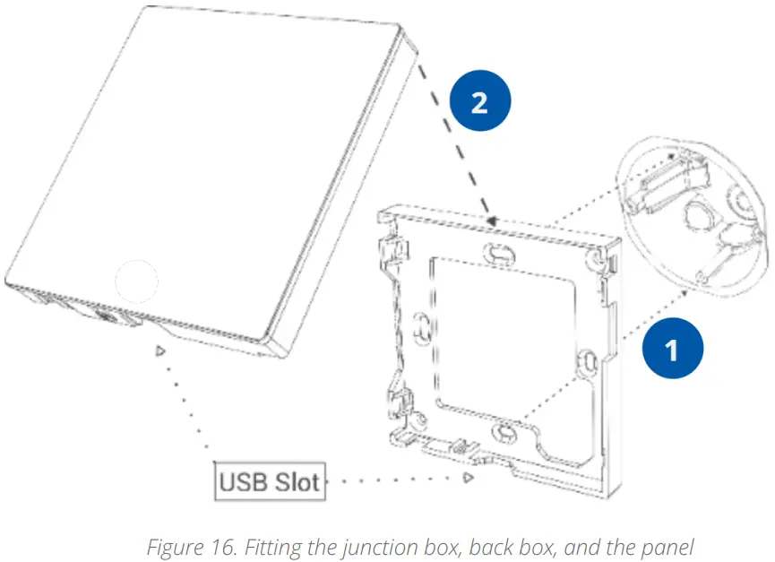 Step 3: Gently push the bottom corners of the panel to the back box
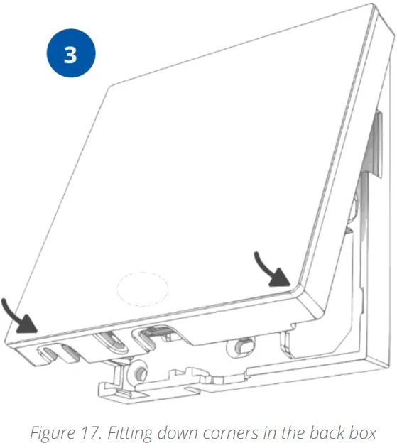
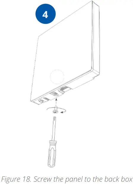
Step 4: Screw the panel to the back box. Turn the screw clockwise.
![]() iSMA CONTROLLI S.p.A.
iSMA CONTROLLI S.p.A.
– Via Carlo Levi 52, 16010
Sant’Olcese (GE) – Italy
[email protected]
www.ismacontrolli.com
DMP254en
1st Issue rev. 0
04/2022


