EURAPO KORC2XX Integrated Comfort Systems User Manual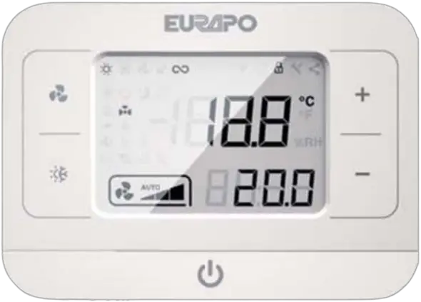
General warning
The product cannot be used by people (including children) with reduced physical, mental or sensory capabilities or inexperienced persons unless they received, through a delegated responsible person, surveillance or a training or proper instruction about the product.
Each operation for installation and/or maintenance on OMNIBUS 360 controllers must be executed by qualified personnel only. EURAPO refuses every responsibility for damages caused by incorrect installation or tampering or improper use of the controller.
For safety reasons, during installation, maintenance or repairing phase the following instructions must be observed:
- always wear work gloves;
- do not expose the electronic board to flammable gas;
- do not install the console in areas with risks of explosion or corrosion, in moist rooms, in open air or severely dusty air.
Before proceeding with any installation and/or maintenance operation or before removing any protection device, make sure that the electronic board has been disconnected from the power supply.
Electrical connections must respect the safety norms and rules of the Country where the product is installed. Always ground the unit.
Do not twist, remove or pull the electrical cables connected to the electronic board, even if it is not connected to the power supply.
Make sure the electrical system can provide the necessary operating current for the normal use of the electronic board in addition to the other electronic devices already present in the same system.
Do not remove the safety labels on the product. If not readable, ask for replacement. It is very dangerous to touch the electronic board with wet parts of the body or barefoot. No water sprays should reach the electronic board.
DESCRIPTION
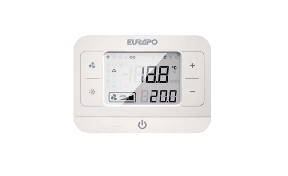
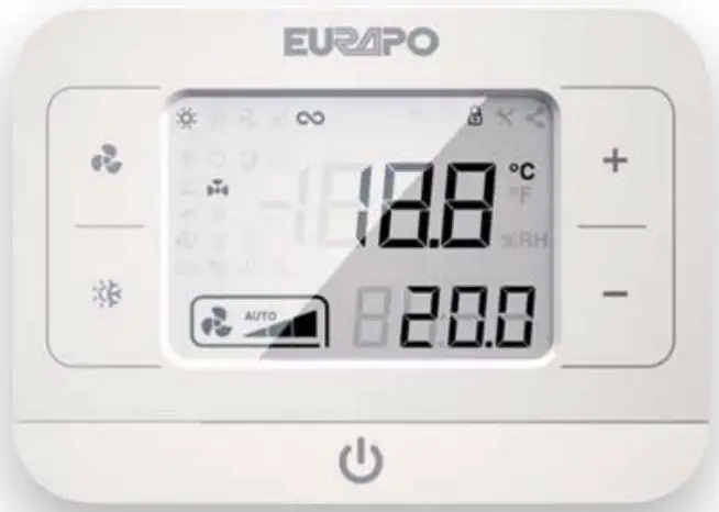
The remote ROUND DISPLAY Console of OMNIBUS 360 is designed for controlling water terminal units (fan coil units, cassettes, high pressure ducted units) for air conditioning and heating applications in domestic, residential or public buildings.
It is composed by an electronic board located in a plastic casing, LCD screen, touch buttons and one NTC integrated air sensor. A buzzer can acknowledge the correct receipt of all commands.
It is designed for wall installation and it has to be connected to the OPower card (installed on the water terminal unit) with 4 wires, for power supply and data exchange.
USER INTERFACE
| Commands | Description |
 | Fan speed button |
 | Summer/Winter button |
| Setpoint setting button (up) | |
| Setpoint setting button (down) | |
| On/Off button |
| Icons | Description |
| Room temperature: visualization of the room temperature (°Celsius or Fahrenheit by choice). | |
| Setpoint: visualization of the room temperature setpoint. | |
| Fan speed: visualization of the fan speed (low, med, high or automatic). |
| Status icons | Description |
 | Heating mode: the controller operates in Winter mode. |
 | Cooling mode: the controller operates in Summer mode. |
| Dead band zone: temperature interval in which the controller is not operating neither in Winter nor in Summer mode. | |
 | Fan mode: the controller operates in ventilation mode only. |
| Continuous fan mode: by reaching the setpoint, the ventilation proceeds at low speed. | |
 | Anti-frost function: the heating valve opens if the room temperature reaches the minimum set value(with console in position OFF). |
 | Destratification function: the fan runs to avoid stratification of the air (i.e. with air sensor at the air intake of the unit). |
 | Economy mode: energy saving by shifting the setpoint. |
 | Electric heater active: the electric heater is energized. |
 | Valve active: the regulating valve is energized. |
 | Forced ventilation: ventilation is forced by a contact (i.e., in case of operation with electric heater). |
 | Service tool – I/O status: reading of input-output states. |
 | Lock buttons mode: deactivation/activation of the buttons on the remote console. |
 | Service tool – Parameters: reading/writing of the OPower parameters. |
| Alarms and Warnings | Description |
 | Warning missing connection: there is no communication between remote console and OPower card. |
 | Warning Window open: by open window, all outputs of the controller are deactivated. |
 | Warning Condensate pump: condensing water in the drain pan reached a dangerous level. |
 | Warning WS water temperature sensor: water is not hot (in Winter) or cold (in Summer) enough. |
 | Warning Dirty filter: a timer indicates that it is necessary to clean/replace the air filter. |
 | Motor alarm: all outputs of the controller are deactivated. |
 | Electric heater alarm: the electric heater has reached too high temperature values. |
| Check sensor alarm: the air outlet temperature is not according to the season set. | |
 | Generic temperature sensors alarm: one or more sensors are detecting anomalies. |
FUNCTIONS
In order to activate the controller, press the button ![]() until the main mask appears on the screen.
until the main mask appears on the screen.
In order to turn OFF the controller, press the button ![]() until “OFF” appears on the screen.
until “OFF” appears on the screen.
Summer/Winter switch
In order to select the operating mode, press the button ![]() until the desired season appears on the screen.
until the desired season appears on the screen.
Setpoint setting
In order to set the desired setpoint (in step of 0,5°C), press the buttons ![]() and
and ![]() .
.
Fan speed setting
For selecting the fan speed press the button ![]() , until the desired speed is visualized (1 – 2 – 3 – AUTO).
, until the desired speed is visualized (1 – 2 – 3 – AUTO).
In AUTO mode, the fan speed changes according to the difference between setpoint temperature and room temperature (the highest is the temperature difference, the highest is the fan speed)
Alarms and warnings
To reset alarms present on the display, press simultaneously for 3 seconds the buttons ![]() and
and ![]()
Alarms
| Code | Description |
| A1 | Alarm no AS: air temperature sensor not present or providing a not valid value. |
| A2 | Alarm no WS: water temperature sensor not present or providing a not valid value. |
| A3 | Alarm no CS: check sensor at the air outlet not present(or water temp. sensor in a 4-pipe system) or providing a not valid value. |
| A4 | Motor alarm: overheating of the motor(for motors with external safety protection, optional). |
| A5 | Electric heater alarm: check sensor temperature above the threshold, with Electric heater ON. |
| A6 | Check sensor alarm: air outlet temperature not hot (in heating mode) or cold (in cooling mode) enough. |
| A7 | Alarm no SE: air temperature sensor inside the remote console not present or providing a not valid value. |
| A8 | Configuration alarm: wrong configuration of the parameters or MODBUS registers. |
Warnings
| Code | Description |
| U1 | TMAX warning: water temperature in cooling mode is not cold enough. |
| U2 | TMIN warning: water temperature in heating mode is not warm enough. |
| U3 | Anti-frost warning: air temperature is too low, anti-frost function active (heating valve activated). |
| U4 | Connection warning: wrong connection between remote console and OPower card on the unit. |
| U5 | Dirty filter warning: the air filter is dirty and it needs to be cleaned or replaced. |
| U6 | Condensate pump warning: high water level in the drain pan, condensate pump active, cooling valve deactivated. |
| U7 | Window open warning: by open window, fan and valves are deactivated. |
Lock buttons
In order to lock the buttons, press simultaneously for 3 seconds the buttons ![]() and and then together
and and then together ![]() and
and ![]() : the padlock symbol appears on the display. Repeat the procedure to unlock.
: the padlock symbol appears on the display. Repeat the procedure to unlock.
Backlight
Backlight is active by pressing any button and it deactivates after a certain period of time settable by the relevant parameter (default value is 30 seconds).
Service Tool:
/O status
To enter the I/O menu, press simultaneously for 5 seconds the buttons ![]() and ; to exit the menu press the button .
and ; to exit the menu press the button .
In this menu it is possible to visualize input and output status of the OPower card. Press ![]() and
and ![]() to select the desired parameter. Values can only be read.
to select the desired parameter. Values can only be read.
| Name | Description |
| C1 | Value read by the SE temperature sensor inside the console [°C]. |
| C2 | Value read by the AS room temperature sensor [°C]. |
| C3 | Value read by the WS water temperature sensor [°C]. |
| C4 | Value read by the CS air outlet temperature sensor [°C]. |
| C5 | Value read by the temperature sensor connected to the multipurpose terminals [°C]. |
| C6 | Room temperature value given by Modbus [°C]. |
| C7 | Lasting time for the room temperature value given by Modbus [seconds]. |
| C8 | Voltage given to the EC motor [V]. |
| C9 | Operating status of the AC motor. |
| C10 | Status of the modulating heating valve. |
| C11 | Status of the modulating cooling valve. |
| C12 | Status of the ON/OFF heating valve. |
| C13 | Status of the ON/OFF cooling valve. |
| C14 | Status of the electric heater output. |
| C15 | Status of the multipurpose input. |
| C16 | Status of the pressure switch/condensate pump alarm input. |
| C17 | Status of the window contact input. |
| C18 | Status of the EC motor alarm input. |
| C19 | Working operation period for dirty filter indication [hours]. |
| C20 | Modbus address of the slave unit with alarm. |
| C21 | Type of alarm of the slave unit. |
| C22 | Setup number. |
| C23 | CRC (factory code). |
Parameters
To enter the Parameters menu, turn OFF the console and press simultaneously for 3 seconds the buttons ![]() and
and ![]() ; to exit the menu press the button for 3 seconds.
; to exit the menu press the button for 3 seconds.
Select the desired parameter with buttons ![]() and
and ![]() and then confirm with .
and then confirm with .
Modify the value of the selected parameter with buttons ![]() and
and ![]() , then confirm with .
, then confirm with .
Press button ![]() to go back to the parameter list without saving the modified value.
to go back to the parameter list without saving the modified value.
| Name | Description |
| P1 | Type of system: 2-pipe (0) or 4-pipe (1). |
| P2 | Summer/Winter switch: manual or by BMS (0), based on water temperature with WS (1), based on air temperature (2), centralized (3), only Cooling (4), only Heating (5). |
| P3 | Value of the proportional band [°C]. |
| P4 | Value of the dead band [°C]. |
| P5 | Fan mode: Thermostated (0), Continuously running in Cooling mode (1), Continuously running in Heating mode (2), Continuously running always (3). |
| P6 | Delayed fan starting [seconds]. |
| P7 | Delayed fan stopping, to cool the electric heater [seconds]. |
| P8 | Electric heater operating mode: Not active (0), Exchanger integration (1), Emergency Heat (2), Summer Emergency Heat (3), Replacement (4). |
| P9 | Interval before activating the destratification function (value 0 = not active) [minutes]. |
| P10 | Duration of the destratification function [minutes]. |
| P11 | Change of setpoint in Economy mode [°C]. |
| P12 | Status of the window contact: Normally open (0), Normally closed (1). |
| P13 | Definition of the multipurpose input: Not active (0), Differential pressure switch (2), Forced Standby (3), Centralized summer/winter switch (4), AC motor alarm (5), Forced ventilation (6), Economy (7), External air sensor (8). |
| P14 | Status of the multipurpose input: Normally open (0), Normally closed (1). |
| P15 | Minimum water temperature for fan enabling in Heating mode (value 25 = the function is not active) [°C]. |
| P16 | Maximum water temperature for fan enabling in Cooling mode [°C]. |
| P17 | Minimum CS air outlet temperature in Heating mode [°C]. |
| P18 | Maximum CS air outlet temperature in Cooling mode [°C]. |
| P19 | Offset of the AS air temperature sensor [°C]. |
| P20 | Offset of the CS Check Sensor [°C]. |
| P21 | Offset of the WS water temperature sensor [°C]. |
| P22 | Offset of the SE air temperature sensor inside the remote console [°C]. |
| P23 | Offset of the air sensor connected to the multipurpose input [°C]. |
| P24 | Constant correction value of the room temperature in Heating mode [°C]. |
| P25 | Constant correction value of the room temperature in Cooling mode [°C]. |
| P26 | Minimum room temperature setpoint [°C]. |
| P27 | Maximum room temperature setpoint [°C]. |
| P28 | Min fan speed voltage (EC motor) [%]. |
| P29 | Med fan speed voltage (EC motor) [%]. |
| P30 | Max fan speed voltage (EC motor) [%]. |
| P31 | LOCALBUS address. |
| P32 | MODBUS address. |
| P33 | Restore of factory setting with password 465. |
| P34 | Level of backlight brightness. |
| P35 | Duration of backlight. |
DIP switch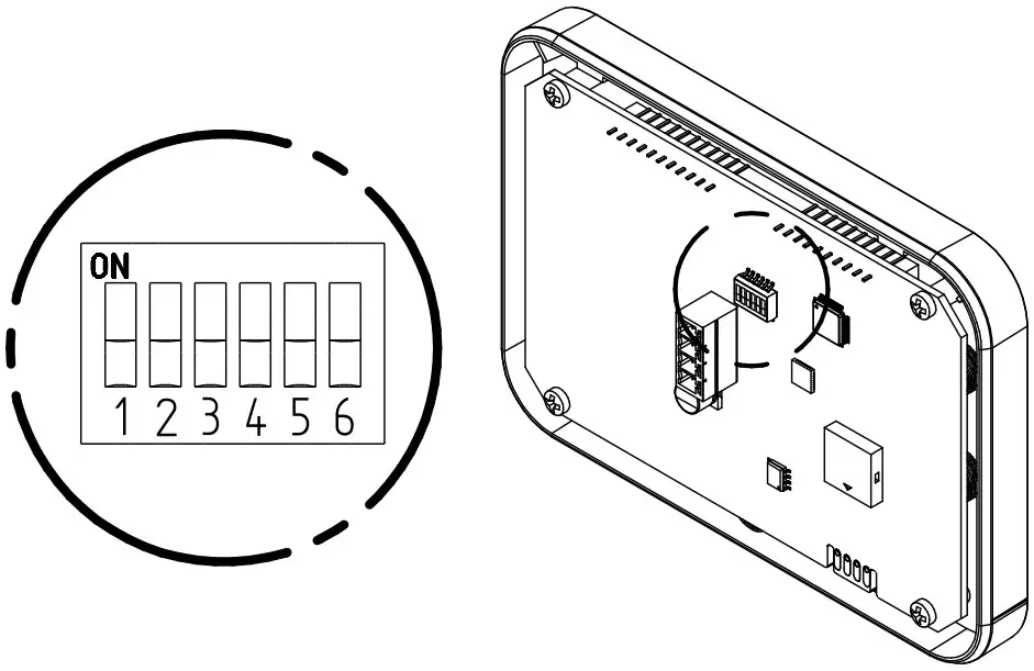
| Combination | Description | |
| DSW 1 | Activation (ON) and deactivation (OFF) of the terminating resistor for the Console Bus line *. | |
| DSW 2 | Visualization of the room temperature and setpoint in Celsius (OFF) or Fahrenheit (ON). | |
| DSW 3 | Activation (OFF) or deactivation (ON) of the buzzer. | |
| DSW | 4 ON5 OFF6 OFF | Visualization of the setpoint instead of the room temperature. |
| DSW | 4 OFF5 ON6 OFF | Setpoint is not visualized. |
| DSW | 4 OFF5 OFF6 ON | Alarms and warnings are not visualized. |
The activation of the terminating resistor must be defined by the installer, basing on the specific installation.
INSTALLATION
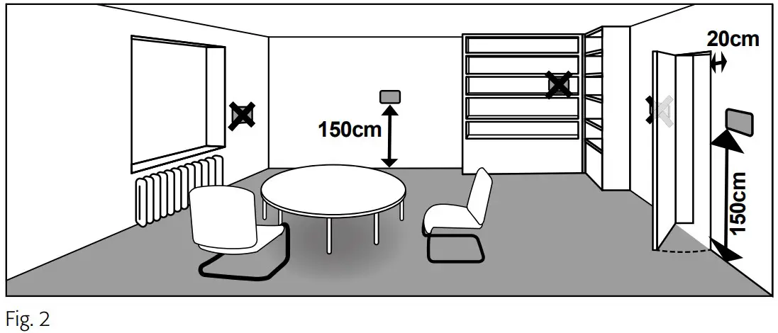
For a correct calibration of the console, it is necessary to set the constant correction values of the room temperature (P24 and P25).
The console cannot be installed in a bathroom within the protected volumes 1 and 2 (Fig. 1).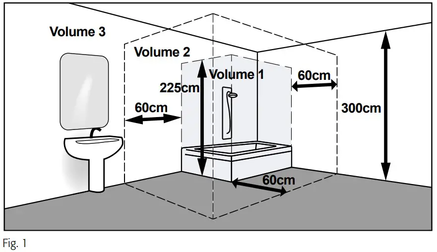
The console is connected to the OPower card with a double insulated 4-wire cable (AWG 22) and through this cable it receives power supply and exchanges information via RS-485 Console Bus network.
Console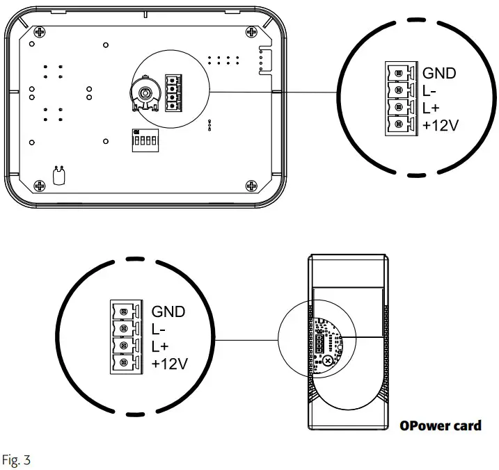
Cables coming from a junction box in the wall
Insert the cables through the central back opening or the side slots of the back plastic 2 of the console.
Fix the back plastic 2 to the wall.
Make the electrical connections by using the 4-pole connector supplied with the console, by respecting polarity (Fig. 3).
Install the console by fixing the front plastic 1 : make a little pressure to interlock it.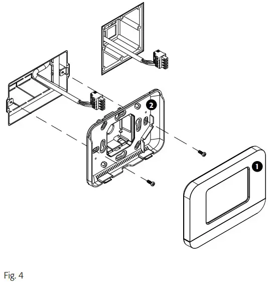
Cables coming from a junction box in the wall (on-wall version)
Fix the plastic bottom panel 3 to the wall.
Insert the cables through the central back opening or the side slots of the back plastic 2 of the console.
Fix the back plastic 2 to the bottom panel 3 .
Make the electrical connections by using the 4-pole connector supplied with the console, by respecting polarity (Fig. 3).
Install the console by fixing the front plastic 1 : make a little pressure to interlock it
Cables coming from an external cable duct on the wall (on-wall version)
Drill the plastic bottom panel 3 to let the wires in. Fix the plastic bottom panel 3 to the wall.
Once the cables are inside the bottom panel 3 , insert them through the central back opening or the side slots of the back plastic 2 of the console.
Fix the back plastic 2 to the bottom panel 3 .
Make the electrical connections by using the 4-pole connector supplied with the console, by respecting polarity (Fig. 3).
Install the console by fixing the front plastic 1 : make a little pressure to interlock it.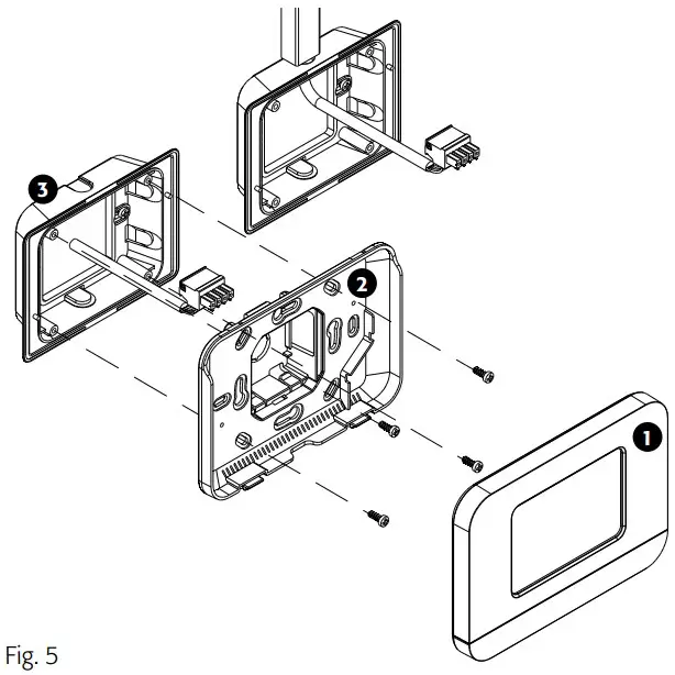
TECHNICAL FEATURES
| Power supply | 12[Vdc]. |
| Absorbed power | 0.192 [W]. |
| Protection grade | IP 30 after installation. |
| Operating conditions | 0÷50 [°C] – 10÷90[%] (without condensation). |
| Storage temperature | -10/+60 [°C]. |
| Weight | 70 [g]. |
ON-WALL VERSION
Plastic bottom panel for installation on the wall.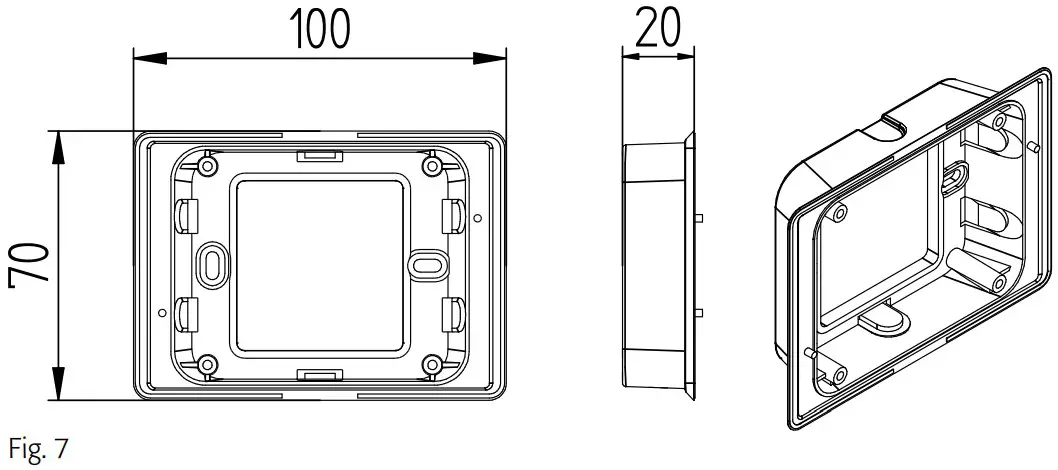
DISPOSAL
Consumable parts and replaced components must be dismissed in accordance to the safety norms and environmental protection standards
At the end of its service life the unit must be delivered to an authorised recycling centre.
A. Information on Disposal for Users (private households)
- In the European Union
Attention: If you want to dispose of this equipment, please do not use the ordinary dust bin! Used electrical and electronic equipment must be treated separately and in accordance with legislation that requires proper treatment, recovery and recycling of such material. Following the implementation by member states, private households within the EU states may return their used electrical and electronic equipment to designated collection facilities free of charge*. In some countries* your local retailer may also take back your old product free of charge if you purchase a similar new one.
Please contact your local authority for further details. If your used electrical or electronic equipment has batteries or accumulators, please dispose of them separately beforehand according to local requirements. By disposing of the products correctly you will help ensure that the waste undergoes the necessary treatment, recovery and recycling and thus prevent potential negative effects on the environment and human health which could otherwise arise due to inappropriate waste handling - In other Countries outside the EU
If you wish to discard this product, please contact your local authorities and ask for the correct method of disposal. For Switzerland: used electrical or electronic equipment can be returned free of charge to the dealer, even without purchasing a new product. Further collection facilities are listed on a homepage of www.swico.ch or www.sens.ch.
B. Information on Disposal for Business Users
- In the European Union
If the product is used for business purposes and you want to discard it, please contact your EURAPO dealer who will inform you about the take-back and possible related costs. Small products (and small amounts) might be taken back by your local collection facilities. - In other Countries outside the EU
If you wish to discard this product, please contact your local authorities and ask for the correct method of disposal
DECLARATION OF CONFORMITY
EURAPO SRL, with head office in via Malignani 12, 33170 Pordenone, hereby declares under its own responsibility that the ROUND DISPLAY unit described in this manual complies with provisions of the following European Directives
- Low voltage Directive 2014/35/EU;
- Electromagnetic compatibility Directive 2014/30/EU;
- Ecodesign Directive 2009/125/CE;
- RoHS Directive 2011/65/UE;
- (RAEE) Directive 2012/19/UE;
- Regulation EC 1907/2006 (REACH) and that all the following harmonized standards and/or technical specifications have been applied:
- EN 55014-1:2006 + A1:2009 + A2:2011 Electromagnetic compatibility – Requirements for household appliances, electric tools and similar apparatus – Part 1: Emission;
- EN 61000-3-2:2014 Electromagnetic compatibility (EMC) Part 3-2: Limits for harmonic current emissions (equipment input current ≤ 16 A per phase);
- EN 61000-3-3:2013 Electromagnetic compatibility (EMC) Part 3: Limits Section 3: Limitation of voltage changes, voltage fluctuations and flicker in low-voltage supply systems for equipment with rated current ≤ 16 A per phase and not subject to conditional connection;
- EN 55014-2:2015 Electromagnetic compatibility – Requirements for household appliances, electric tools and similar apparatus – Part 2: Immunity – Product family standard;
- EN 60335-1:2013-05 + A11:2015 Household and similar electrical appliances – Safety
- Part 1: General requirements;
- EN 60335-2-40:2005 + A1:2007 + A13:2012 Household and similar electrical appliances
- Safety – Part 2: Particular requirements for electric heat pumps, air conditioning units and dehumidifiers;
- EN IEC IEEE 82079-1:2020 Preparation of information for use (instructions for use) of products: Principles and general requirements.
NOTES
For the correct identification of spare parts, always indicate the article code and description.
In case of replacement parts, always ask for original components.
By unpacking the product make sure there are no damages and that the unit corresponds to the ordered model. In case of damage or incongruence with the ordered model, contact the distributor providing serial number and model of the component received.
WARRANTY
Electronic parts are guaranteed for 24 months beginning from the date the control is delivered ex-works in Pordenone. The warranty covers only factory defects and not malfunctions caused by improper installation or wrong connection.
As programs and technologies are always improving, description, data and drawings must be intended as merely indicative and can be modified without any notice.
Eurapo Srl Via A. Malignani, 12 33170 Pordenone – Italy
T +39 0434 572552
F +39 0434 28667
[email protected]
www.eurapo.it