![]() INSTALLATION &
INSTALLATION &
OPERATION MANUAL Alpha Dual-Duct
VAV Controller
BAC-8007/BAC-8207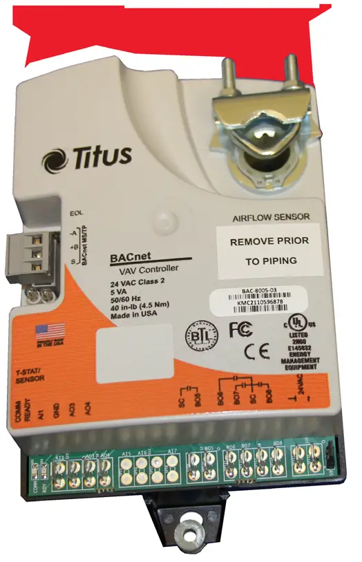 IOM
IOM
BAC-8007/BAC-8207
Section 1 — About the Controllers
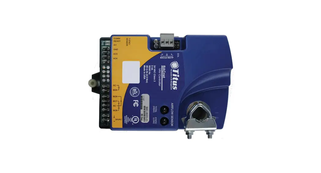
This section provides a description of the Titus Alpha BAC-8007 and BAC8207 VAV controllers. It also introduces safety information.
Review this material before installing or operating the controllers.
The BAC-8007 and BAC-8207 are native BACnet, direct digital controllers designed for VAV terminal units. An integrated actuator and the supplied programs make these ideal controllers for temperature setback, overrides, reheat and other HVAC sequences. Install these versatile controllers in stand-alone environments or networked to other BACnet devices. As part of a complete facilities management system, the BAC-8007 and BAC-8207 controllers provide precise monitoring and control of connected points.
- BACnet MS/TP compliant
- Standard VAV control sequences are incorporated to provide pressure independent control of a dual-duct VAV unit to control heating and cooling
- On-board airflow sensor for use with a single or multi-point differential pressure measuring station or pitot tube.
- Control indoor air quality and local lighting
Models:
BAC-8007 Dual-duct VAV controller with 90 second actuator
BAC-8207 Dual-duct VAV controller with 60 second actuator and UL 864 smoke control application
SPECIFICATIONS
| Analog inputs | All inputs are configured as analog |
| Active inputs | 2 |
| Passive inputs | 4 |
| Air flow sensor | 1 |
| Actuator position Key features | 1 |
| Key features | Standard units of measure Overvoltage input protection |
| Connector | Spade connectors, 0.25 inch |
| Conversion | 12–bit analog–to–digital conversion |
| Input range | 0–12 volts DC |
| Outputs, analog | 2 |
| Key features | Output short protection Configured as BACnet analog objects Standard units of measure |
| Connector | Spade connectors, 0.25 inch |
| Conversion | 12–bit analog–to–digital conversion |
| Output voltage | 0–10 volts DC |
| Output current | 30 mA per output, 30 mA total for all analog outputs |
| Outputs, binary | 4 triacs for external equipment 2 for the internal actuator |
| Key features | Optically isolated triac output |
| Conversion | 12–bit analog–to–digital conversion |
| Connector | Spade connectors, 0.25 inch |
| Output range | Maximum switching 24 VAC at 3 amperes |
| Communications | |
| BACnet MS/TP | EIA–485 operating at rates up to 76.8 kilobaud Removable screw terminal block Wire size 12–24 AWG |
| Sensor jack | RJ-45 jack compatible with model STE-8000 and STE-6000 models with RJ-45 jacks |
| Supported objects | |
| Control Basic | See PIC statement for supported BACnet objects 5 program areas in BAC-8007 6 program areas in BAC-8207 |
| PID loop objects | 8 |
| Value objects | 60 analog, 32 binary, and 12 multistate |
| Memory | Programs and program parameters are stored in nonvolatile memory Auto restart on power failure |
SPECIFICATIONS (continued)
Applications programs
Titus Controls supply the BAC-8×07 with programming sequences for dual-duct VAV applications:
- Dual-duct VAV heating and cooling
- Monitor CO2 to control indoor air quality
- Control local lighting with motion sensing
- Fan control
- Balancing
- UL 864 smoke controll (BAC-8207 only)
Air flow sensor features
Configured as BACnet analog input object. CMOS differential pressure 0-2 inches of water (0-500 Pa) measurement range. Internally linearized and temperature ompensated. Span accuracy 4.5% of reading. Barbed connections for 1/4 FR tubing. Range dependent upon DP pickup, tubing size/length and connections.
Actuator specifications
| Torque | 40 in-lb. (4.5 N•m) |
| Angular rotation | 0 to 95° Adjustable end stops at 45° and 60° rotation |
| Motor timing, BAC-8007 | 90 sec./90° at 60 Hz 108 sec./90° at 50 Hz |
| Motor timing, BAC-8207 | 60sec./90° at 60 Hz 72 sec./90° at 50 Hz |
| Shaft size | Directly mounts on 3/8 to 5/8 inch (9.5 to 16 mm) round or 3/8 to 7/16 inch (9.5 to 11 mm) square damper shafts |
| Regulatory | UL 916 Energy Management Equipment FCC Class B, Part 15, Subpart B BACnet Testing Laboratory listed as an application specific controller (ASC) UL 864 smoke controls (BAC-8207 only) |
| Installation | |
| Supply voltage | 24 volts AC, -15%, +20% 5 VA |
| Weight | 13.2 ounces (376 grams) |
| Case material | Flame retardant plastic |
| Environmental limits | |
| Operating | 32 to 120° F (0 to 49° C) |
| Shipping | –40 to 140° F (–40 to 60° C) |
| Humidity | 5–95% relative humidity (non-condensing) |
DIMENSIONS
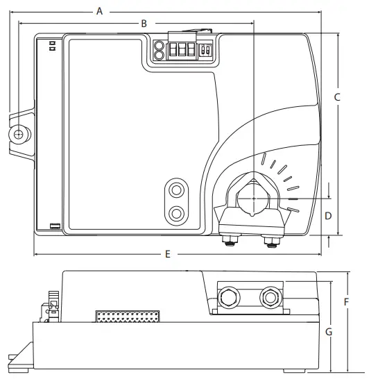
Table 1-1 BAC- 8000 dimensions
| A | B | C | D | E | F | G |
| 6.53 in . 166 mm | 4 .89 in . 124 mm | 4 .25 in . 108 mm | 0 .77 in . 19 mm | 6 .00 in . 152 mm | 2 .14 in . 54 mm | 1 .92 in . 49 mm |
SAFETY CONSIDERATIONS
Titus assumes the responsibility for providing you a safe product and safety guidelines during its use. Safety means protection to all individuals who install, operate, and service the equipment as well as protection of the equipment itself. To promote safety, we use hazard alert labeling in this manual. Follow the associated guidelines to avoid hazards.
| Danger represents the most severe hazard alert. Bodily harm or death will occur if danger guidelines are not followed. | |
| Warning represents hazards that could result in severe injury or death. | |
| Caution indicates potential personal injury or equipment or property damage if instructions are not followed. | |
| Notes provide additional information that is important. | |
| Provides programing tips and shortcuts that may save time. |
Section 2 — Installing the Controller
This section provides important instructions and guidelines for installing the BAC-8007 and BAC-8207 controllers. Carefully review this information before installing the controller.
Installing the VAV controller includes the following topics that are covered in this section.
- Setting the rotation limits on page 9
- Mounting on page 10
- Connecting Inputs on page 14
- Connecting Outputs on page 12
- Connecting to an MS/TP Network on page 14
- Connecting an Airflow Sensor on page 17
- Connecting Power on page 17
In addition to the topics, see the section Dual-duct connections on page 18 for connecting the controllers to a TSP-8000 actuator for dual-duct operation.
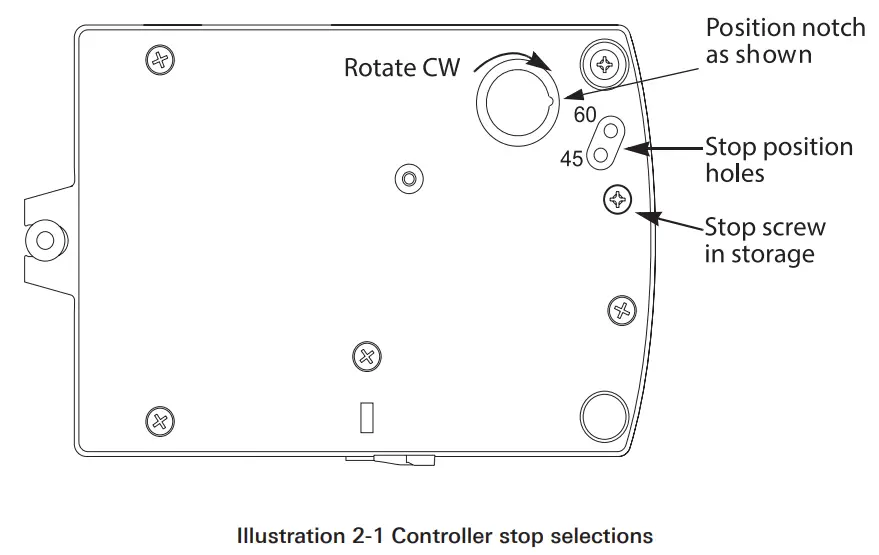
SETTING THE ROTATION LIMITS
Before mounting the controller, set the rotation limits with the supplied stop screw. Installing the stop screw limits the shaft rotation to either 45 or 60 degrees.
![]() CAUTION
CAUTION
Before setting the rotation limits on the controller, refer to the damper position specifications in the VAV control box to which the controller will be attached. Setting rotation limits that do not match the VAV damper may result in improper operation or equipment damage.
To set the rotational limits:
- Turn the controller over so you have access to the back.
- Manually rotate the actuator fully clockwise as viewed from the back.
- Remove the stop screw from its storage location and clean any debris from the threads.
- Insert the screw into the correct stop position hole.
- Tighten the screw only until the head touches the plastic in the bottom of the recess.
MOUNTING
Mount the controller inside of a metal enclosure. To maintain RF emissions specifications, use either shielded connecting cables or enclose all cables in conduit.
Mount the controller directly over the damper shaft. A minimum shaft length of 2.0 inch (51 mm) is required.
NOTE
The controller is designed to directly mount to 3/8 to 5/8 inch (9.5 to 16mm) round or 3/8 to 7/16 (9.5 to 11mm) square damper shafts. Mount the controller close enough to the pitot tubes to keep the tubing length to a minimum. In typical installations the controller’s inputs and sensors are within 24 inches of each other.
Mount the controller as follows:
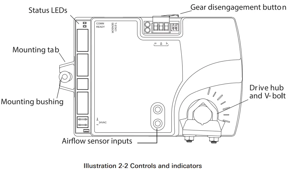
- Loosen the nuts on the U-bolt until the shaft can fit through the collar.
- Place the controller on the damper shaft in the approximate final position. Position the controller loosely against the mounting surface so that the mounting bushing can float freely in the mounting tab.
- Center the mounting bushing in the slot of the mounting tab and secure it using a #8 self-tapping screw.
- Manually position the damper in the full open position.
- Adjust the drive hub as follows:
a. If the damper rotates counter clockwise to close, depress the gear disengagement button and rotate the drive hub to the full clockwise position then release the button.
b. If the damper rotates clockwise to close, depress the gear disengagement button and rotate the drive hub to the full counter clockwise position then release the button. - Lock the hub to the shaft by evenly tightening the V-bolt nuts to 30 to 35 in-lbs.
CONNECTING INPUTS
The BAC-8007 and BAC-8207 controllers have preconfigured analog inputs to support the supplied programs. The inputs cannot be changed to binary or accumulator inputs. Only six inputs have externally available physical terminals. All of the inputs are preconfigured for the application programs supplied in the dual-duct controllers and are listed in Table 2-1.
Table 2-1 BAC-8007 and BAC-8207 input objects
| Object | Function | Name | Unit | Location | Pull up |
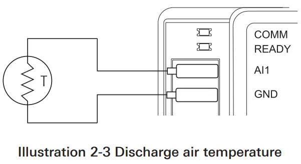
| AI1 | Discharge Air Temperature | DISCHARGE AIR | °F | Terminal block | 10kΩ |
| AI2 | Space Sensor | SPACE SENSOR | °F | RJ-45 | 10kΩ |
| AI3 | Space Setpoint | SPACE SETPOINT | °F | RJ-45 | 10kΩ |
| AI4 | Primary Duct Pressure | PRIMARY DUCT | wc | Internal airflow sensor | N/A |
| AI5 | Secondary Duct Pressure | SECONDARY DUCT | wc | Terminal block | None |
| AI6 | Secondary Damper Position | SECONDARY POS | Volts | Terminal block | 10kΩ |
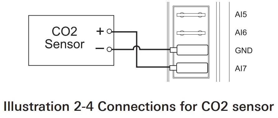
| AI7 | CO2 | CO2 | PPM | Terminal block | None |
| AI8 | Primary Damper Position | PRIMARY POS | Volts | Internal damper position | N/A |
Discharge air temperature: Connect a 10k , Type 3 thermistor temperature probe to the discharge air temperature input. The input includes the internal pull-up resistor. An STE-1405 sensor is suitable for this application. Follow the instructions supplied with the sensor for installation. See Temperature Setpoints on page 20 for setting up discharge air temperature limiting that requires this input sensor.
Space Temperature Input: The space temperature input is connected only through the RJ-45 thermostat and sensor input jack. It is a configured as an analog input for STE-6010, STE-6014, and STE-6017 sensors. If an STE-8000 sensor is connected to the controller, this input is ignored. See Connecting to Sensors on page 13.
Space Setpoint: The space setpoint input is connected only through the RJ-45 thermostat and sensor input jack. It is a configured for the setpoint dials on STE-6014 or STE-6017 sensors. If an STE-6010 or STE-8000 sensor is connected to the controller, this input is ignored. See Connecting to Sensors on page 13.
Primary Duct Pressure: The primary duct pressure input is an internal measurement from the airflow sensor.
Secondary Duct Pressure: The secondary duct pressure input is an analog input preconfigured to connect to the P Out terminal of a TSP-8000 series actuator for dual-duct operation. The TSP-8000 P Out represents actual airflow detected by the TSP-8000 airflow sensor. See the section Dual-duct Connections on page 18 for connection details.
Secondary Damper Position: The secondary damper position input is preconfigured to connect to the position potentiometer of an TSP8000 series actuator for dual-duct operation. See the section Dual-duct Connections on page 18 for connection details.
CO2 input: Connect a CO2 sensor with an active output to the CO2 input. Set the sensor for a voltage output. An STE-1001 sensor is suitable for this application. Follow the instructions supplied with the sensor for sensor power, installation and calibration.
Primary Damper Position: The primary damper position input is preconfigured as an analog input that represents the position of the internal damper. Primary Duct Pressure The primary duct pressure input is an internal measurement from the airflow sensor.
CONNECTING OUTPUTS
The BAC-8007 and BAC-8207 controllers have eight preconfigured outputs to support the supplied programs. Only six have externally available physical terminals. All of the outputs are preconfigured for the application programs supplied in the in the dual-duct controllers and are listed in Table 2-2.
Table 2-2 BAC-8007 and BAC-8207output objects
| Object | Function | Name | False Value | True Value | Default Value | Type |
| BO1 | Damper Clockwise | DAMPER CW | Neutral | Clockwise | Neutral | Internal |
| BO2 | Damper Counter Clockwise | DAMPER CCW | Neutral | Counterclockwise | Neutral | Internal |
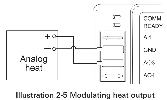
| AO3 | Analog Heat | ANALOG HEAT | 0 | 0-10 VDC | ||
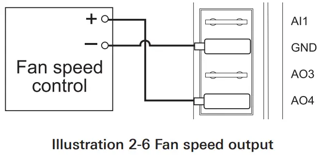
| AO4 | Fan Speed | FAN SPEED | 0 | 0-10 VDC | ||
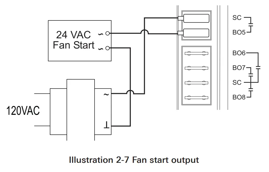
| BO5 | Fan Start/Stop | FAN | On | Off | Off | Triac |
| BO6 | Secondary Damper Clockwise | SEC damper cw | Neutral | Clockwise | Neutral | Triac |
| BO7 | Secondary Damper Counterclockwise | Sec damper ccw | Neutral | Counterclockwise | Neutral | Triac |
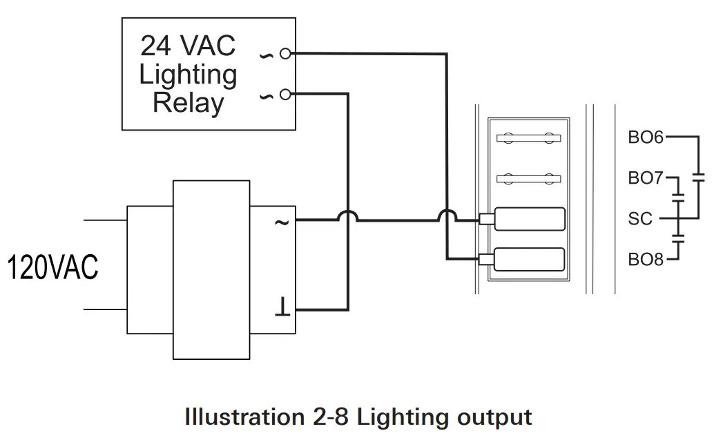
| BO8 | Lighting | Heat/lite | On | Off | Off | Triac |
Damper Clockwise and Clockwise: The damper outputs are binary output objects that control the motion of the internal damper.
Analog Heat: The analog heat output controls modulating analog reheat.
This output is active only if the controller is set up for reheat. For staged reheat applications, use an REE-5001 relay.
Fan Speed: Controls the speed of a variable speed fan if the controller is set up for fan operation.
Fan Start/Stop: The fan start output is preconfigured to either start or stop a single speed fan or enable a multispeed fan. The output is a triac that can switch up to 1 ampere at 24 volts AC.
Secondary Damper Clockwise and Counterclockwise: The secondary damper output terminals are preconfigured to control the position of the damper of a TSP-8000 series actuator for dual-duct operation. The outputs are triacs that can switch up to 1 ampere at 24 volts AC. See the section Dual-duct Connections on page 18.
Local lighting: The lighting output is preconfigured to work with the motion sensor in an STE-8201 sensor to automatically control lights located in the same space as the VAV. The output is a triac that can switch up to 1 ampere at 24 volts AC.
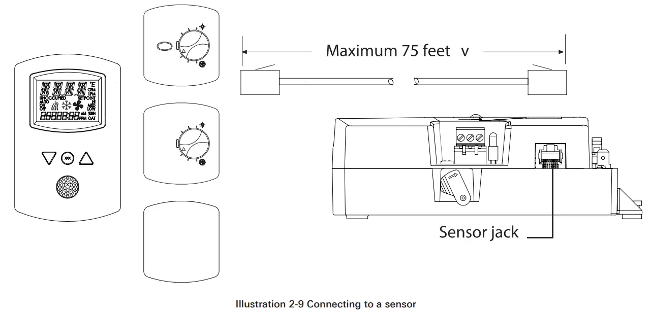
CONNECTING TO SENSORS
Connect any of the following sensors to the RJ-45 thermostat and sensor jack.
- STE-8001STE-8201
- STE-6010
- STE-6014
- STE-6017
Link the controller to sensors with standard straight-through Ethernet cables up to 75 feet long. See the installation guide supplied with the sensors for complete sensor installation instructions.
No programming or configuration is required for the supported sensors.
The controller is configured to automatically detect which type of sensor is connected to it.
CONNECTING TO AN MS/TP NETWORK
The BAC-8000 series controllers are BACnet MS/TP compliant controllers.
Connect them only to a BACnet MS/TP network.
See Application Note AN0404A, Planning BACnet Networks for additional information about installing controllers. Connections and wiring
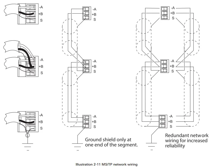
Use the following principles when connecting a controller to an MS/TP network:
- Connect no more than 128 addressable BACnet devices to one MS/TP network. The devices can be any mix of controllers or routers.
- To prevent network traffic bottlenecks, limit the MS/TP network size to 60 controllers.
- Use 18 gauge, twisted pair, shielded cable with capacitance of no more than 51 picofarads per foot for all network wiring. Belden cable model #82760 meets the cable requirements.
- Connect the -A terminal in parallel with all other – terminals.
- Connect the +B terminal in parallel with all other + terminals.
- Connect the shields of the cable together at each controller. For KMC BACnet controllers use the S terminal.
- Connect the shield to an earth ground at one end only.
- Use a KMD–5575 repeater between every 32 MS/TP devices or if the cable length will exceed 4000 feet (1220 meters). Use no more than four repeaters per MS/TP network.
- Place a KMD–5567 surge surpressor in the cable where it exits a building.

![]() NOTE
NOTE
The MS/TP terminals are labeled -A, +B and S. The S terminal is provided as a connecting point for the shield. The terminal is not connected to the ground of the ontroller. When connecting to controllers from other manufacturers, verify the shield connection is not connected to ground.
CONNECTING TO AN MS/TP NETWORK (CONTINUED)
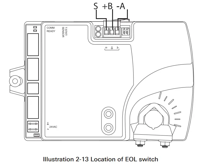
End of the line termination switches
The controllers on the physical ends of the EIA-485 wiring segment must have end-of-line termination installed for proper network operation. Set the end-of-line termination to On using the EOL switches.
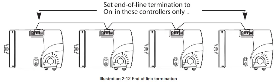
Illustration 2-13 shows thez position of the BAC-8000 End-of-Line switches associated with the MS/TP inputs.
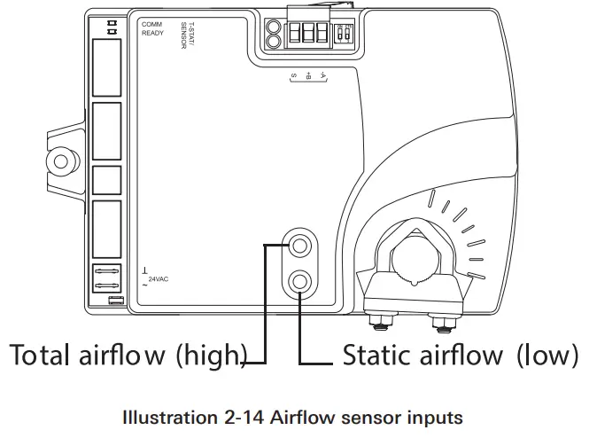
CONNECTING AN AIRFLOW SENSOR
An airflow sensor is incorporated as one of the inputs to the controller. Remove the plugs and connect the tubing from the pitot assembly to the airflow sensor inputs next to the drive hub. (See Illustration 2-14). The airflow sensor is programmed as Input 1.
CONNECTING POWER
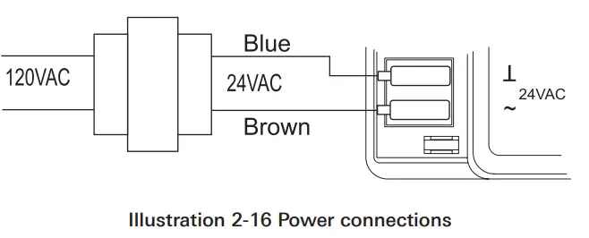
The controllers require an external, 24 volt, AC power source. Use the following guidelines when choosing and wiring transformers.
- Use a Class-2 transformer of the appropriate size to supply power to the controllers. Titus recommends powering only one controller from each transformer.
- Do not run 24 volt, AC power from within an enclosure to external controllers.
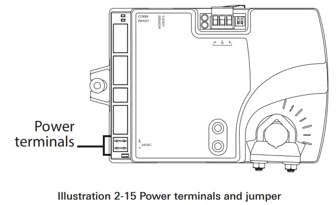
Connect the 24 volt AC power supply to the power terminal block on the lower right side of the controller near the power jumper. Connect the ground side of the transformer to the ground terminal and the AC phase to the phase ~ terminal. Power is applied to the controller when the transformer is powered.
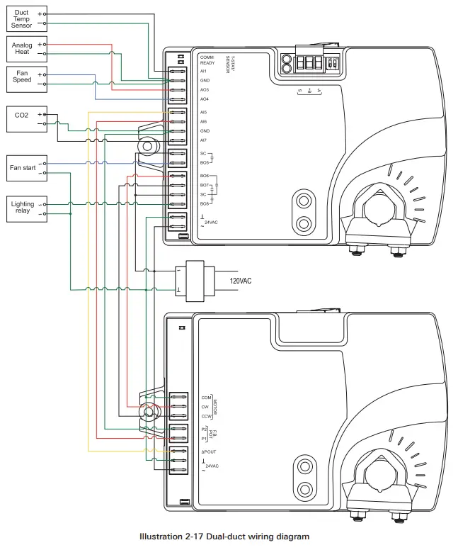
DUAL-DUCT CONNECTIONS
The BAC-8007 and BAC-8207 controllers are configured by the manufacturer for dual-duct operation. Connect the controllers to a TSP-8000 series actuator as shown in the illustration Dual-duct wiring diagram below.
Section 3 — Setting up Dual-Duct Controllers
The topics in this section cover setting up the BAC-8007 and BAC-8207 for dual-duct VAV operation. These are advanced topics for controls technicians and engineers.
The BAC-8007 and BAC-8207 dual-duct VAV controllers are set up by the manufacturer to operate as soon as power is applied and connected as described in the section Installing the Controller beginning on page 9.
Setting up the dual-duct VAV controllers may include setting BACnet objects with a BACnet Operator Workstation such as TotalControl. The objects may also be set up with a STE-8001 or STE-8201. The following topics are covered in this section.
- Setting Temperature Setpoints on page 20
- Setting Airflow Setpoints on page 21
- Setting the VAV Terminal Unit Parameters on page 22
- Setting Up Local Lighting control on page 23
- Network Communications on page 19
![]() CAUTION
CAUTION
Change only the present values of the objects listed in this section.
Changing any other objects or properties will result in improper operation.
NETWORK COMMUNICATIONS
Before connecting the controller to a BACnet MS/TP network, configure the following network parameters with either a BACnet operator workstation or temporarily connecting an STE-8001 or STE-8201 to the controller.
Device instance: Set from 0 to 4,194,302. A device instance number must be unique across the BACnet internetwork.
Baud: Valid baud settings are 9600, 19200, 38400, and 76800.
MAC: Set from 0 to 127. Must be unique on the MS/TP network to which the controller is connected.
SETTING TEMPERATURE SETPOINTS
The space temperate setpoints listed in Table 3-1, “Temperature setpoints,” below are used to control the controller VAV operation. The temperature setpoints have default values, but may be manipulated depending on which type of wall sensor is connected to the controller. Occupied cooling and heating setpoints: These setpoints are user controlled space setpoints that originate from an attached sensor. If no sensor is attached the values for these setpoints are manually entered by a controls technician.
Unoccupied cooling and heating setpoints: The unoccupied setpoints are manually entered values to set the heating and cooling temperature when the space is unoccupied.
Minimum cooling setpoint: A manually entered value to limit the occupied cooling setpoint regardless of the value entered by the user.
Maximum heating setpoint: A manually entered value to limit the
occupied heating setpoint regardless of the value entered by the user.
Minimum setpoint differential: Sets the minimum temperature separation between occupied heating and cooling setpoints.
Standby differential: This differential is added or subtracted from the occupied temperature setpoints to calculate the standby setpoints.
SAT changeover temperature: Sets the supply air temperature at which the controller will change from heating to cooling. The changeover takes place when the supply air temperature is 2° above or below the discharge air temperature setpoint.
Table 3-1 Temperature setpoints
| Object | Description | Name | Default |
| AV5 | Occupied Cooling Setpoint | OCC CL STPT | 74°F |
| AV6 | Occupied Heating Setpoint | OCC HT SPT | 70°F |
| AV7 | Unoccupied Cooling Setpoint | UNOCC CL STPT | 80°F |
| AV8 | Unoccupied Heating Setpt | UNOCC HT STPT | 64°F |
| AV9 | Minimum Cooling Setpt | MIN CL STPT | 70°F |
| AV10 | Maximum Heating Setpoint | MAX HT STPT | 76°F |
| AV11 | Minimum Setpoint Differential | MIN STPT DIFF | 4°F |
| AV12 | Standby Differential | STBY DIFF | 3°F |
| AV37 | SAT Changeover Temp | SAT CHANGEOVER | 75°F |
SETTING AIRFLOW SETPOINTS
The airflow setpoints are limits for VAV unit operation. All values are entered by a controls technician.
Minimum and maximum cooling airflow: Sets the airflow limits through the VAV unit when in the cooling mode.
Minimum and maximum heating airflow: Sets the airflow limits through the VAV unit when in the heating mode.
Minimum and maximum fan speed: Sets the limits on the fan speed. See Connecting outputs on page 12 for details for controlling a fan that is part of the VAV unit.
Minimum and maximum ventilation flow: Sets the minimum and maximum airflow limits for indoor air quality.
Table 3-2 Airflow setpoints
| Object | Description | Name | Defaults |
| AV13 | Min Cooling Airflow | MIN COOL FLOW | 0 CFM |
| AV14 | Max Cooling Airflow | MAX COOL FLOW | 400 CFM |
| AV15 | Min Heating Airflow | MIN HEAT FLOW | 0 CFM |
| AV16 | Max Heating Airflow | MIN HEAT FLOW | 400 CFM |
| AV32 | Minimum Fan Speed | MIN FAN SPEED | 0% |
| AV33 | Maximum Fan Speed | MAX FAN SPEED | 100% |
| AV55 | Minimum Vent Flow | MIN VENT FLOW | 0 CFM |
| AV56 | Maximum Vent Flow | MAX VENT FLOW | 350 CFM |
SETTING THE VAV TERMINAL UNIT PARAMETERS
Terminal unit parameters set basic operating parameters and enable options such as reheat and series or parallel fan operation.
Reheat: Enables and sets the type of reheat. Choose from the available types of reheat from the following list.
None: Reheat is not enabled.
Staged: Not available on dual-duct models)
Modulating: The reheat output varies from 0-10 volts.
Floating: Not available on dual-duct models.
Time proportional: Not available on dual-duct models.
Reheat equipment is connected to the controller as described in the topic Connecting Outputs on page 12.
Dual-duct mixing minimum airflow: Sets the minimum airflow which may be different than the minimum cooling or heating airflow.
Damper direction to close: Defines which direction the damper will turn to decrease airflow.
CCW: The actuator turns counterclockwise to close the damper.
CW: The actuator turns clockwise to close the damper.
Primary duct K-factor: A property of the specific VAV unit and airflow sensor to which the primary controller is attached. This constant is supplied by the VAV unit manufacturer.
Secondary duct K-factor: A property of the specific VAV unit and airflow sensor to which the secondary controller is attached. This constant is supplied by the VAV unit manufacturer
Fan operation: Sets the type of VAV fan in the VAV terminal unit.
None: No fan is connected to the controller.
Series: The VAV unit includes a series fan. The fan runs during a fresh air purge, when the space is occupied or in standby.
Parallel: The VAV unit includes a parallel fan. The fan runs when there is a call for heat during a fresh air purge, when the space is occupied or in standby.
Table 3-3 Unit parameters
| Object | Description | Name | Default |
| MSV3 | Reheat Type | REHEAT | None |
| AV17 | Dual Minimum | DUAL MINIMUM | 200 CFM |
| AV18 | Primary K factor | PR K FACT | 904 |
| BV10 | Clockwise Close | CLOCKWISE CLOSE | CCW |
| MSV2 | Fantype Configuration | FAN CONFIG | None |
SETTING UP LOCAL LIGHTING CONTROL
Automatic local lighting can controlled by the motion sensor in an STE8201 connected to the controller. Local lighting is set up either with software or an attached STE-8201.
Lighting control enable: When enabled, local lights will be turned on or off based on motion detected by an STE-8201.
Light off delay: Sets the interval local lights will remain turned on after the last motion is detected by an STE-8201.
Lighting equipment is connected to the controller as described in the topic Connecting Outputs on page 12.
Table 3-4 Local lighting options
| Object | Description | Name | Default |
| BV11 | Lighting Control Enable | LIGHTING CONTROL | Enable |
| AV42 | Light off delay | LITE OFF DELAY | 15 minutes |
BALANCING AIRFLOW
An airflow balancing program is included in BAC-8000 series controllers. See the manual STE-8000 and STE-8201 Sensor Installation Guide for balancing instructions.
605 Shiloh Rd
Plano TX 75074
ofc: 972.212.4800
fax: 972.212.4884
Redefine your comfort zone.™ | www.titus-hvac.com![]() Redefine your comfort zone.™
Redefine your comfort zone.™


