Yealink ETV65 Touch Display User Guide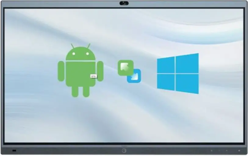
Package Contents
The pictures of the endpoint and accessories in this guide are for reference only. Please use the accessories in the package, and follow the guide for installation. Yealink assumes no responsibility for any damage caused by improper installation methods
Standard Accessories
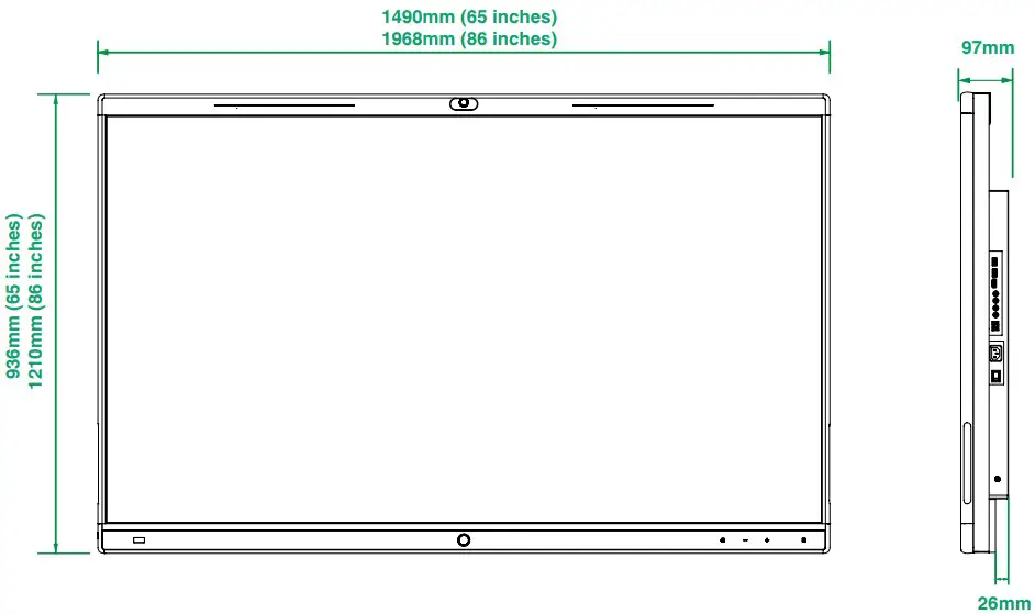
- ETV65/86

- Wall-mounted bracket *65-inch and 86-inch wall-mounted bracket are different in size and cannot be mixed

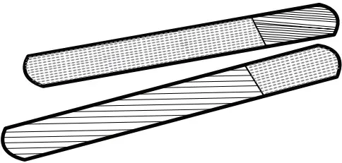
- Pen x 2

- Quick Start Guide (Wall-Mounted)

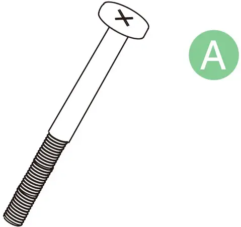
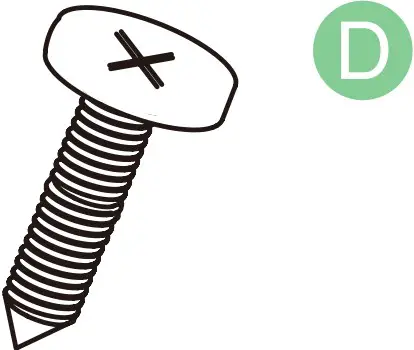
- Security screw x 2 (M5*100mm)

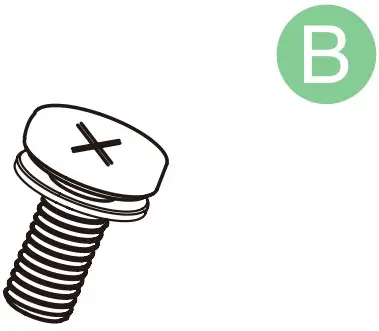
- Screw x 4 (M8*35mm) *For locking the back of the endpoint

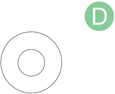
- Rubber gasket x 5 (φ32) *Pad on the back of the endpoint

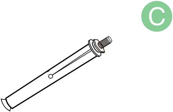
- Expansion bolt x 8 (8*80mm) *For vertical, load-bearing solid wall or concrete wall

- Self-tapping screw x 8 (6*50mm) *For planks or other reinforced walls

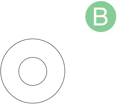
- Metal gasket x 8 (φ8*1.6mm) *For fixing self-tapping screws

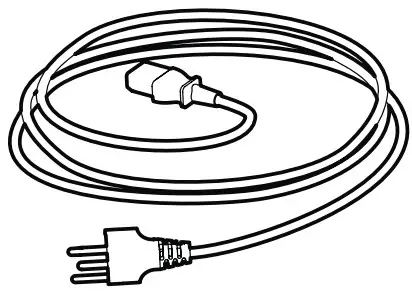
- 3 m Power Cable

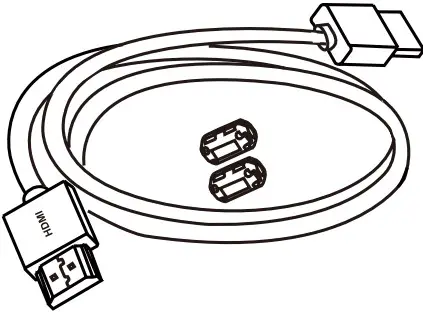
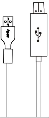
- 0.8 m HDMI cable

- 0.8 m USB-B cable

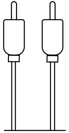
- RCA cable * Only ETV86

- Cable Ties x 3


Endpoint Installation
![]() If you are using a floor stand for installation, please refer to Quick Start Guide (Floor-Mounted).
If you are using a floor stand for installation, please refer to Quick Start Guide (Floor-Mounted).
![]() Take and place all components gently to avoid damage.
Take and place all components gently to avoid damage.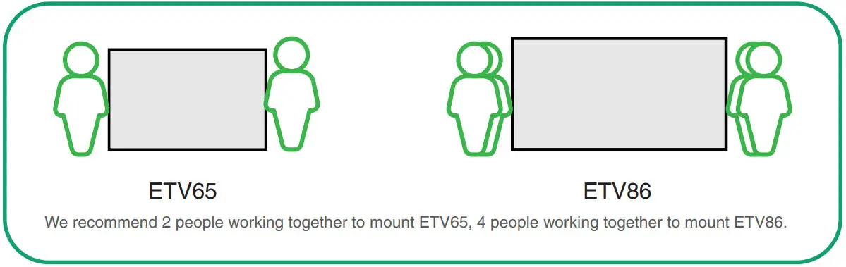
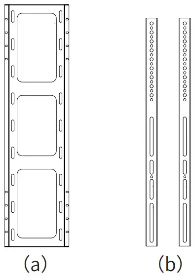
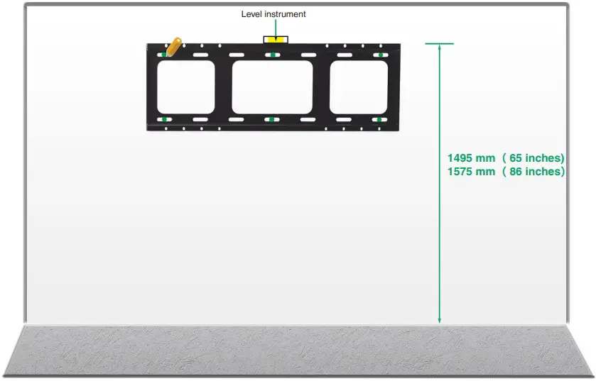
Determine wall-mounted bracket (a) installation position
 Please install on a vertical, load-bearing solid wall or concrete wall (use expansion screw) or planks, other reinforced walls (use self-tapping screws) with more than 20 cm thickness.
- For other type of walls, please reinforce the wall and verify the feasibility before installation. Verification method: Install a screw to carry out a single screw load test for 1 minute (ETV65 load-bearing 35 kg, ETV86 load-bearing 45 kg), and the installation can continue if the screw is not loose.
- The wall-mounted bracket for ETV65 and ETV86 are only different in size, and the installation method is the same.
- The installation height data is for reference only. You can choose a suitable position as needed.

![]() At least 6 screws for ETV65. At least 8 screws for ETV86.
At least 6 screws for ETV65. At least 8 screws for ETV86.
Fix the expansion screws/self-tapping screws at the marked positions on the wall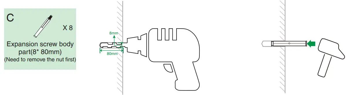
![]() If the wall is planks, other reinforced walls, install wall-mounted bracket with in-package self-tapping screws.
If the wall is planks, other reinforced walls, install wall-mounted bracket with in-package self-tapping screws.
Methods: To install wall-mounted bracket, sleeve the self-tapping screw (6*50mm) into the metal gasket, then drill it into the wall.
Install the wall-mounted bracket (a) to the wall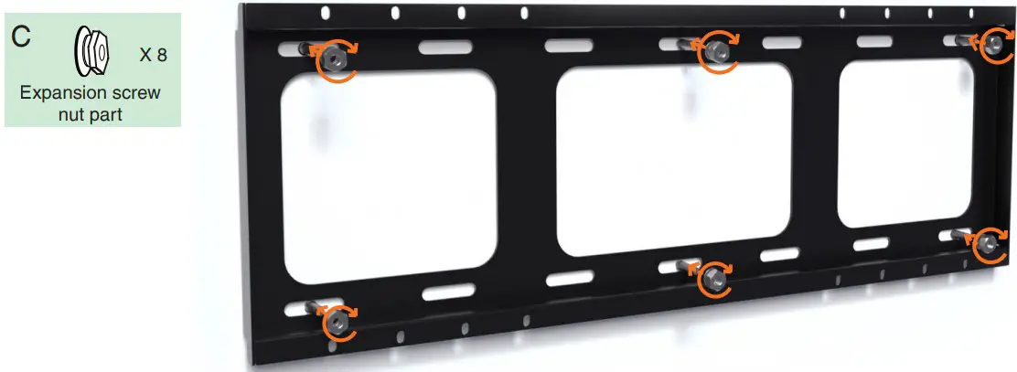
Install wall-mounted bracket (b) on the back of the endpoint
Tear the patch and remove the screws on the back of the endpoint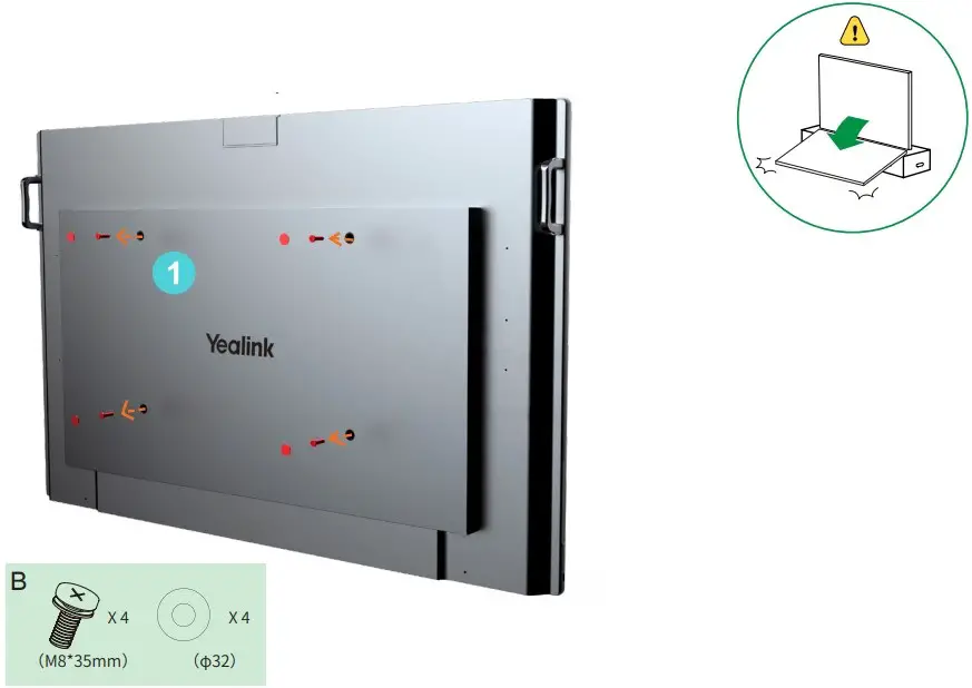
Put the rubber gasket on the back of endpoint, install the wall bracket (b) and lock the screws and gaskets
We recommended that the screw be installed to the third hole of the wall-mounted bracket (b)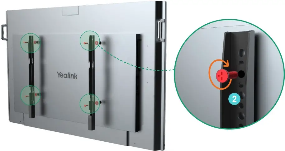
![]() If the installation height is slightly inappropriate, you can adjust the installation hole position to meet your needs.
If the installation height is slightly inappropriate, you can adjust the installation hole position to meet your needs.
Mount the endpoint and lock the security screw on the back of the endpoint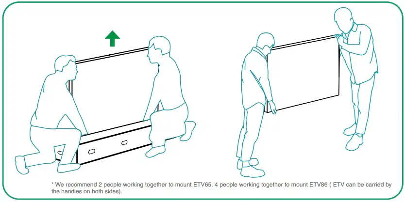
![]() If the power port the conference room are located on the back wall of the endpoint to be installed, connect the cables first before installing the endpoint.
If the power port the conference room are located on the back wall of the endpoint to be installed, connect the cables first before installing the endpoint.
![]() The wall-mounted bracket (b) on both sides need to be snapped into the slots at the same time.
The wall-mounted bracket (b) on both sides need to be snapped into the slots at the same time.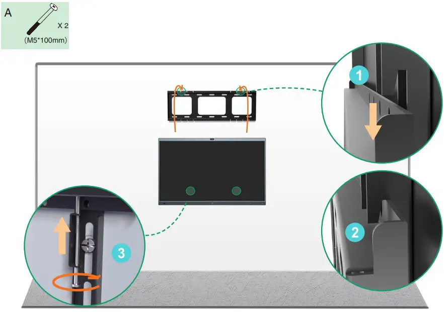
Hardware Component Instructions
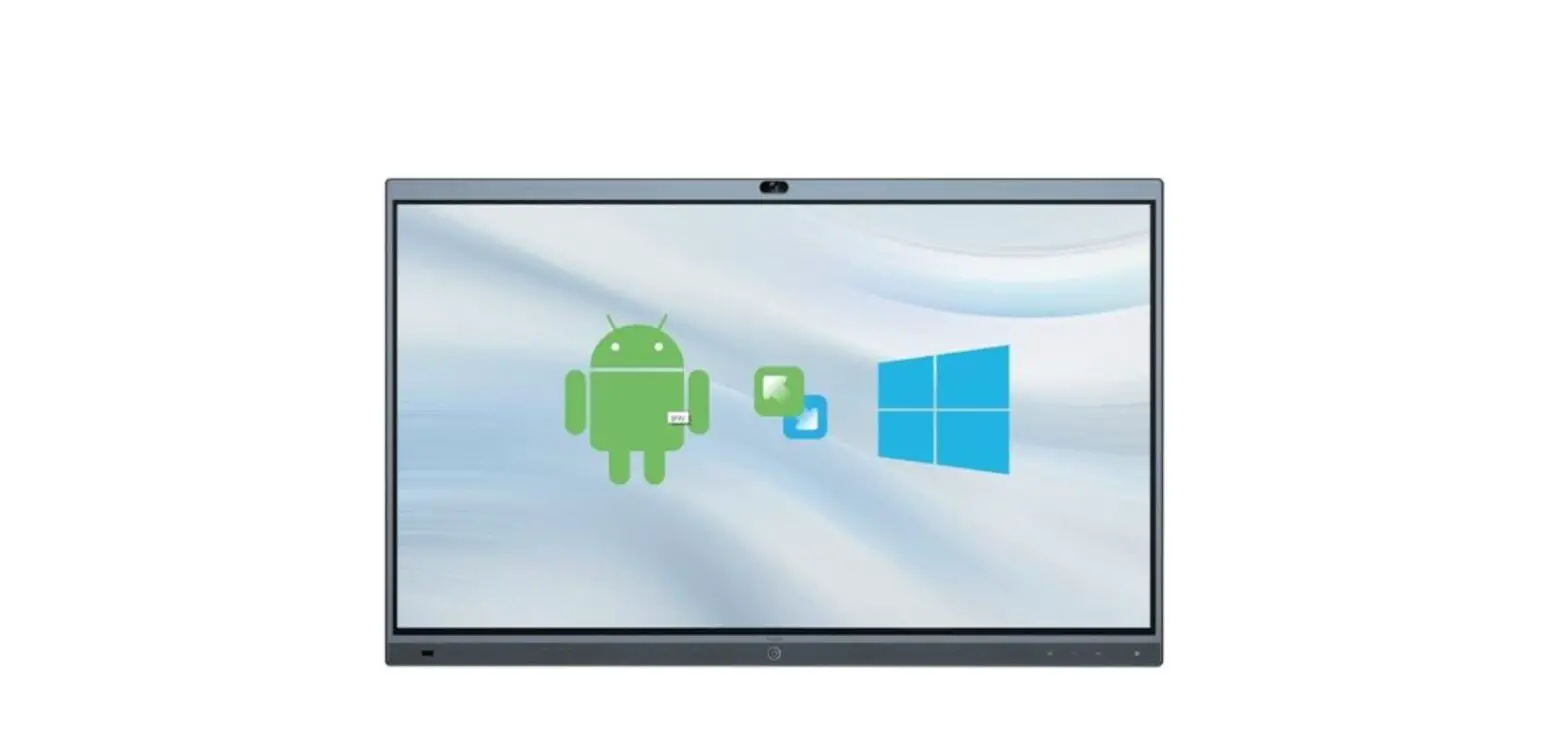
ETV can be used as an extended display of the Meeting Board by connecting the HDMI cable. Meanwhile, you can use the ETV control Meeting Board by connecting both HDMI cable and USB-B cable.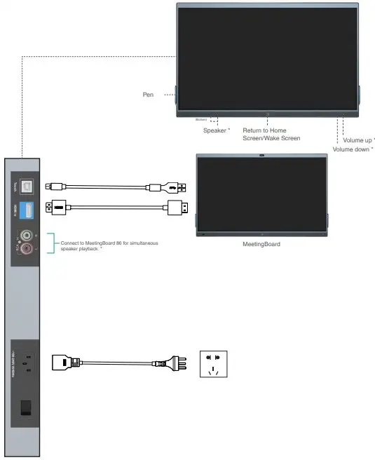
Power on
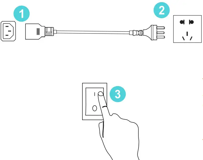
- Insert the end of the power cable into the power port of the endpoint.
- Insert the power cord plug into the outlet.
- Turn the rocker switch button on the left rear of the endpoint to “I” to turn on the endpoint.
Power outage
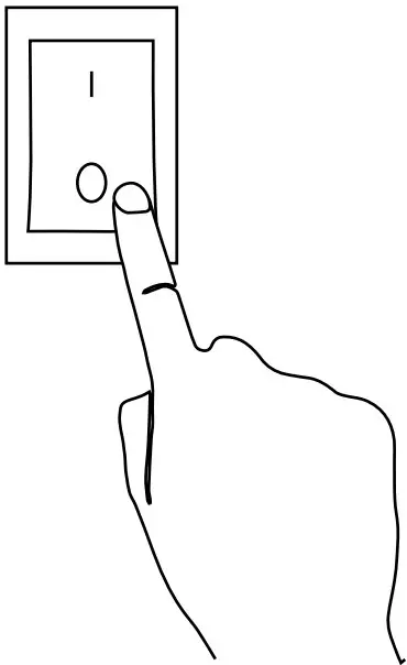
Turn the rocker switch button on the left rear of the endpoint to “O” to turn off the endpoint
Regulatory Notices
Operating Ambient Temperatures
- Operating temperature: +14 to 113°F (-10 to 45°C)
- Relative humidity: 5% to 90%, noncondensing
- Storage temperature: -22 to +158°F (-30 to +70°C)
Warranty
Our product warranty is limited only to the unit itself, when used normally in accordance with the operating instructions and the system environment. We are not liable for damage or loss resulting from the use of this product, or for any claim from a third party. We are not liable for problems with Yealink device arising from the use of this product; we are not liable for financial damages, lost profits, claims from third parties, etc., arising from the use of this product.
Explanation of the symbols
DC symbol
![]() is the DC voltage symbol.
is the DC voltage symbol.
WEEE Warning symbol
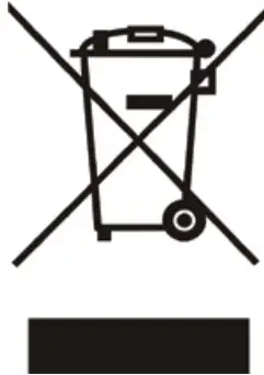
To avoid the potential effects on the environment and human health as a result of the presence of hazardous substances in electrical and electronic equipment, end users of electrical and electronic equipment should understand the meaning of the crossed-out wheeled bin symbol. Do not dispose of WEEE as unsorted municipal waste and have to collect such WEEE separately.
Restriction of Hazardous Substances Directive (RoHS)
This device complies with the requirements of the EU RoHS Directive. Statements of compliance can be obtained by contacting [email protected].
Safety Instructions
Save these instructions. Read these safety instructions before use! The following basic safety precautions should always be followed to reduce risk of fire, electrical shock, and other personal injury
![]() General Requirements
General Requirements
- Before you install and use the device, read the safety instructions carefully and observe the situation during operation.
- During the process of storage, transportation, and operation, please always keep the device dry and clean, avoid collision and crash.
- Please attempt not to dismantle the device by yourself. In case of any discrepancy, please contact the appointed maintenance center for repair.
- Please refer to the relevant laws and statutes while using the device. Legal rights of others should be respected as well.
![]() Environmental Requirements
Environmental Requirements
- Do not cover ventilation openings, this equipment is not intended to be used on soft support.
- The marking information is located at the exterior of the bottom
- Place the device at a well-ventilated place. Do not expose the device under direct sunlight.
- Keep the device dry and free of dusts.
- Do not place the device on or near any inflammable or fire-vulnerable object, such as rubber-made materials.
- Keep the device away from any heat source or bare fire, such as a candle or an electric heater.
![]() Operating Requirements
Operating Requirements
- Do not let a child operate the device without guidance.
- Do not let a child play with the device or any accessory in case of accidental swallowing.
- Please use the accessories provided or authorized by the manufacturer only.
- Do not spill liquid of any kind on the product or use the equipment near water, for example, near a bathtub, washbowl, kitchen sink, wet basement or near a swimming pool.
- When there is smoke emitted from the device, or some abnormal noise or smell, disconnect the device immediately.
- Contact the specified maintenance center for repair.
- Do not insert any object into equipment slots that is not part of the product or auxiliary product.
Cleaning Requirements
- Use a piece of soft, dry and anti-static cloth to clean the device.
Troubleshooting
The usage environment is out of operating temperature range.
1. Use in the operating temperature range.
The cable between the unit and the Yealink device is connected incorrectly.
1. Connect the cable correctly.
Some dust, etc., may be in the port.
1. Clean the port.
Contact your dealer or authorized service facility for any further questions.
FCC CAUTION
This device complies with part 15 of the FCC Rules. Operation is subject to the following two conditions:
- This device may not cause harmful interference, and
- this device must accept any interference received, including interference that may cause undesired operation. Any changes or modifications not expressly approved by the party responsible for compliance could void the user’s authority to operate the equipment.

Contact Information
YEALINK NETWORK TECHNOLOGY CO.,LTD. No.666 Hu’an Rd. Huli District Xiamen City, Fujian, P.R.C YEALINK (EUROPE) NETWORK TECHNOLOGY B.V. Strawinskylaan 3127, Atrium Building, 8th floor, 1077ZX Amsterdam, The Netherlands YEALINK (USA) NETWORK TECHNOLOGY CO., LTD. 999 Peachtree Street Suite 2300, Fulton, Atlanta, GA, 30309, USA Made in China
For more information please scan
Guide & Video
Please read this guide before installation to avoid unnecessary personal injury and damage to the endpoint.