![]()
COMPREHENSIVE SERVICES
We offer competitive repair and calibration services, as well as easily accessible documentation and free downloadable resources.
SELL YOUR SURPLUS
We buy new, used, decommissioned, and surplus parts from every NI series.
We work out the best solution to suit your individual needs.
![]() Sell For Cash
Sell For Cash ![]() Get Credit
Get Credit ![]() Receive a Trade-In Deal
Receive a Trade-In Deal
OBSOLETE NI HARDWARE IN STOCK & READY TO SHIP
We stock New, New Surplus, Refurbished, and Reconditioned NI Hardware.
Bridging the gap between the manufacturer and your legacy test system.
![]() 1-800-915-6216
1-800-915-6216![]() www.apexwaves.com
www.apexwaves.com![]() [email protected]
[email protected]
All trademarks, brands, and brand names are the property of their respective owners.
Request a Quote ![]() SWB-2810
SWB-2810
GETTING STARTED GUIDE
NI Switches
NI SwitchBlock
This document explains how to install, configure, and test the NI SwitchBlock. The carrier ships with the NI-SWITCH instrument driver, which you can use to program the NI SwitchBlock cards.
 Note Before you begin, install and configure your chassis and controller.
Electromagnetic Compatibility Guidelines
This product was tested and complies with the regulatory requirements and limits for electromagnetic compatibility (EMC) stated in the product specifications. These requirements and limits provide reasonable protection against harmful interference when the product is operated in the intended operational electromagnetic environment.
![]()
This product is intended for use in industrial locations. However, harmful interference may occur in some installations, when the product is connected to a peripheral device or test object, or if the product is used in residential or commercial areas. To minimize interference with radio and television reception and prevent unacceptable performance degradation, install and use this product in strict accordance with the instructions in the product documentation.
Furthermore, any changes or modifications to the product not expressly approved by National Instruments could void your authority to operate it under your local regulatory rules.
![]() Caution To ensure the specified EMC performance, operate this product only with shielded cables and accessories.
Caution To ensure the specified EMC performance, operate this product only with shielded cables and accessories.
![]() Caution To ensure the specified EMC performance, the length of all I/O cables must be no longer than 30 m (100 ft).
Caution To ensure the specified EMC performance, the length of all I/O cables must be no longer than 30 m (100 ft).
Verifying the System Requirements
To use the NI-SWITCH driver, your system must meet certain requirements. For more information about minimum system requirements, recommended system, and supported application development environments (ADEs), refer to the readme, which is available on the software media or online at ni.com/updates.
Unpacking the Kit
![]() Caution To prevent electrostatic discharge (ESD) from damaging the device, ground yourself using a grounding strap or by holding a grounded object, such as your computer chassis.
Caution To prevent electrostatic discharge (ESD) from damaging the device, ground yourself using a grounding strap or by holding a grounded object, such as your computer chassis.
- Touch the antistatic package to a metal part of the computer chassis.
- Remove the device from the package and inspect the device for loose components or any other sign of damage.
 Caution Never touch the exposed pins of connectors.
 Note Do not install a device if it appears damaged in any way.
 - Unpack any other items and documentation from the kit.
Store the device in the antistatic package when the device is not in use.
Preparing the Environment
Ensure that the environment in which you are using the NI SwitchBlock meets the following specifications:
PXI Modules
| Operating Environment | |
Ambient temperature range | 0 °C to 55 °C (Tested in accordance with IEC 60068-2-1 and IEC 60068-2-2.) |
Relative humidity range | 10% to 90%, noncondensing (Tested in accordance with IEC 60068-2-56.) |
| Maximum altitude | 2,000 m (at 25 °C ambient temperature) |
| Pollution Degree | 2 |
Indoor use only.
Note Refer to the device specifications on ni.com/manuals.
Verifying the Kit Contents
The items shown in the following figure are necessary to set up and use your NI SwitchBlock.
Figure 1. SwitchBlock Carrier Kit Contents
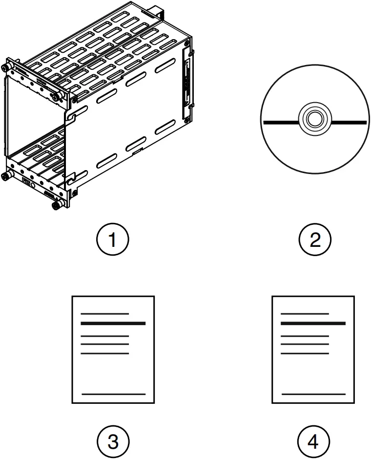
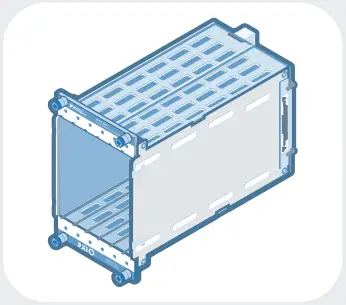
- NI SwitchBlock Carrier
- NI-SWITCH Driver Software DVD
- NI SwitchBlock Getting Started Guide
- Safety, Environmental, and Regulatory Information
Figure 2. SwitchBlock Card Kit Contents
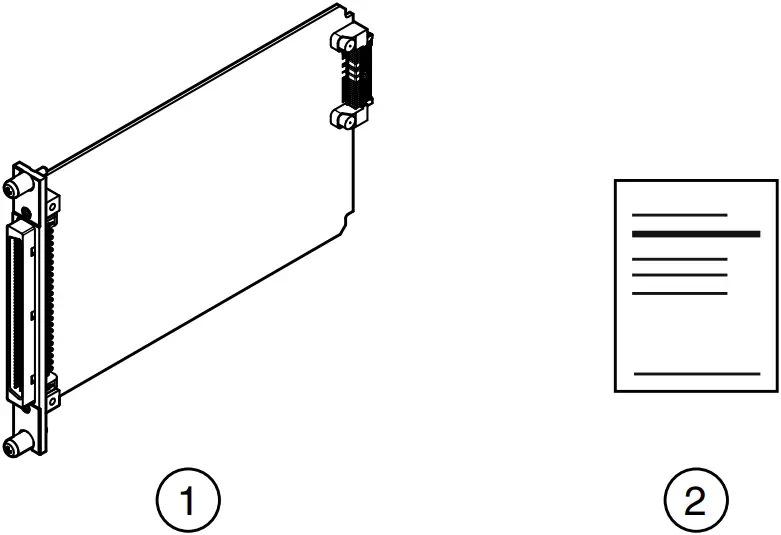
- NI SwitchBlock Card
- Safety, Environmental, and Regulatory Information
In addition to the items contained in the kit, you need the following items to install or operate your device.
NI SwitchBlock Carrier Required Items
- NI PXI chassis or NI PXI Express chassis with hybrid slots
- #1 Phillips screwdriver
Note You can install the NI PXI-2800 carrier for the NI SwitchBlock in an NI PXI Express chassis if the back connector of the carrier connects to a PXI peripheral slot in the chassis.
NI SwitchBlock Card Required Items
- NI SwitchBlock carrier
- #1 Phillips screwdriver
Installing the Software
You must be an Administrator to install NI software on your computer.
- Install an ADE, such as LabVIEW or LabWindows™/CVI™.
- Insert the driver software media into your computer. The installer should open automatically.
If the installation window does not appear, navigate to the drive, double-click it, and double-click autorun.exe. - Follow the instructions in the installation prompts.Note Windows users may see access and security messages during installation. Accept the prompts to complete the installation.
- When the installer completes, select Restart in the dialog box that prompts you to restart, shut down, or restart later.
Installing the Hardware
You must install the software before installing the hardware.
Before you install the hardware, refer to the guidelines in the Maintain Forced-Air Cooling Note to Users at ni.com/manuals to ensure that the device can cool itself effectively.
![]() Caution To prevent damage to the device caused by ESD or contamination, handle the device using the edges or the metal bracket.
Caution To prevent damage to the device caused by ESD or contamination, handle the device using the edges or the metal bracket.
![]() Caution Clean the hardware with a soft, nonmetallic brush. Make sure that the hardware is completely dry and free from contaminants before returning it to service.
Caution Clean the hardware with a soft, nonmetallic brush. Make sure that the hardware is completely dry and free from contaminants before returning it to service.
Installing an NI SwitchBlock Carrier
The NI SwitchBlock carrier holds up to six NI SwitchBlock relay cards and occupies four PXI slots. The carrier can be installed before or after installing cards.
Figure 3. Installing an NI SwitchBlock Carrier
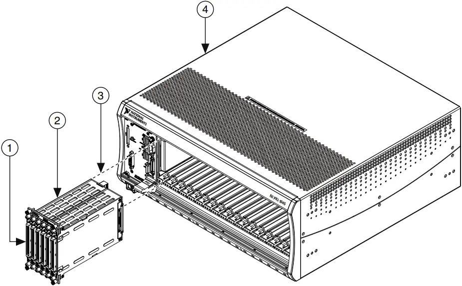
- NI SwitchBlock Card
- NI SwitchBlock Carrier
- PXI Connector
- NI PXI/PXI Express or NI PXI/SCXI Combination Chassis
- Ensure the AC power source is connected to the chassis before installing the carrier.
The AC power cord grounds the chassis and protects it from electrical damage while you install the carrier. - Power off the chassis.
- If the chassis has multiple fan speed settings, ensure that the fans are set to high.
- Position the chassis so that inlet and outlet vents are not obstructed.
For more information about optimal chassis positioning, refer to chassis documentation. - Identify four adjacent empty slots in the chassis for the NI SwitchBlock carrier to occupy.Note The second-to-leftmost slot occupied by the carrier must be compatible with the PXI. The other three occupied slots may be any peripheral or timing slot. Refer to the chassis documentation for details.
- Remove the filler panels of the four slots you have selected for installing the carrier.
- Touch any metal part of the chassis to discharge static electricity.
- Place the carrier edges into the module guides at the top and bottom of the chassis. Slide the carrier into the slot until it is fully inserted.
- Tighten the screws at the top and bottom of the carrier front panel.Note Tightening the top and bottom mounting screws increases mechanical stability and also electrically connects the front panel to the chassis, which can improve the signal quality and electromagnetic performance.
- Cover all empty slots using filler panels or slot blockers to maximize cooling air flow.
Installing an NI SwitchBlock Card
The NI SwitchBlock carrier holds up to six NI SwitchBlock relay cards. The cards can be installed before or after installing the carrier.
Figure 4. Installing an NI SwitchBlock Card
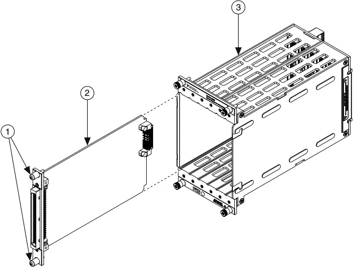
- Screws
- NI SwitchBlock Card
- NI SwitchBlock Carrier
- Ensure the AC power source is connected to the chassis before installing the modules.
The AC power cord grounds the chassis and protects it from electrical damage while you install the modules. - Power off the chassis.
- If the chassis has multiple fan speed settings, ensure that the fans are set to high.
- Position the chassis so that inlet and outlet vents are not obstructed.
For more information about optimal chassis positioning, refer to chassis documentation. - Remove the filler panel of an unused slot in the NI SwitchBlock carrier.
- Touch any metal part of the chassis to discharge static electricity.
- Place the module edges into the module guides at the top and bottom of the carrier. Slide the device into the slot until it is fully inserted.
- Secure the device front panel to the carrier using the front-panel mounting screws.Note Tightening the top and bottom mounting screws increases mechanical stability and also electrically connects the front panel to the carrier, which can improve the signal quality and electromagnetic performance.
- Cover all empty NI SwitchBlock slots using the blank NI SwitchBlock filler panels.
- Power on the chassis.
Configuring the NI SwitchBlock in MAX
Use Measurement & Automation Explorer (MAX) to configure your NI hardware. MAX informs other programs about which devices reside in the system and how they are configured. MAX is automatically installed with NI-SWITCH.
- Launch MAX.
- In the configuration tree, expand Devices and Interfaces to see the list of installed devices.
Installed devices appear under the name of their associated chassis. - Expand your Chassis tree item.
MAX lists all devices installed in the chassis. Your default device names may vary.Note If you do not see your device listed, press <F5> to refresh the list of installed devices. If the device is still not listed, power off the system, ensure the device is correctly installed, and restart. - Record the device identifier MAX assigns to the hardware. Use this identifier when programming the NI SwitchBlock.
- Right-click the carrier in the configuration tree and select Configure to launch the NI SwitchBlock Configuration Panel.
By default, all NI SwitchBlock cards in the carrier appear as single-card devices, as shown in the following figure. Use one the following methods to configure your NI SwitchBlock and designate which cards compose each device:
• Select Combine All or Uncombine All to combine NI SwitchBlock cards in the carrier into devices or to split all cards into single-card devices.
• Right-click a card and select Move To»New Device to create a new device.
• Drag and drop a card into the desired device to create a multicard NI SwitchBlock device. - Select OK to update the configuration tree in MAX.Note If a device name has not been previously specified in the MAX configuration tree, MAX will auto-generate a device name such as SwitchBlock1Dev1.
- Self-test the device by selecting the device in the configuration tree and clicking Self-Test in the MAX toolbar.
The MAX self-test performs a basic verification of hardware resources.
Programming the NI SwitchBlock
You can acquire data interactively using the NI-SWITCH Soft Front Panel (SFP), or you can control the device programmatically using the NI-SWITCH instrument driver. You can then use NI-SWITCH to program the device in the application development environment (ADE) of your choice.
Table 1. NI SwitchBlock Programming Options
Application Programming Interface (API) | Location | Description |
| NI-SWITCH SFP | Available from the Start menu or NI Launcher in Windows 8. | Provides a graphical interface for controlling and viewing the state of your NI SwitchBlock. |
| NI-SWITCH Instrument Driver | LabVIEW—Available on the LabVIEW Functions palette at Measurement I/O»NI-SWITCH | Features a set of operations and attributes that exercise all the functionality of the NI SwitchBlock, including configuration, control, and other device-specific functions. |
| C or LabWindows/CVI— Available at Program Files \IVI Foundation\IVI \Drivers\niSWITCH. | ||
| Installed examples for Visual C/C++ are in the NI-SWITCH Readme. | Refer to the Creating an Application with Microsoft Visual C/C++ topic in the NI Switches Help for information about developing an NI-SWITCH application. |
NI-SWITCH Examples
Examples demonstrate the functionality of the device and serve as programming models and building blocks for your own applications. The NI Example Finder is a utility available for some ADEs that organizes examples into categories and allows you to easily browse and search installed examples. You can see descriptions and compatible hardware models for each example or see all the examples compatible with one particular hardware model.
Table 2. Locating NI-SWITCH Examples
| ADE | How to Locate Examples |
| LabVIEW or LabWindows/CVI | Locate examples with the NI Example Finder. Within LabVIEW or LabWindows/CVI, select Help»Find Examples and navigate to Hardware Input and Output»Modular Instruments. |
| ANSI C or Microsoft Visual C/C++ | Locate examples in the <NIDocDir>\CVI\Samples \niswitch directory, where <NIDocDir>is one of the following directories:
|
Troubleshooting
If an issue persists after you complete a troubleshooting procedure, contact NI technical support or visit ni.com/support.
What Should I Do if the NI SwitchBlock Doesn’t Appear in MAX?
- In the MAX configuration tree, expand Devices and Interfaces.
- Expand the Chassis tree to see the list of installed devices, and press <F5> to refresh the list.
- If the SwitchBlock carrier or SwitchBlock card is still not listed, power off the system, ensure that all hardware is correctly installed, and restart the system.
- Navigate to the Device Manager.
Operating System Description Windows 8 Right-click the Start screen, and select All apps»Control Panel»Hardware and Sound»Device Manager. Windows 7 Select Start»Control Panel»Device Manager. Windows Vista Select Start»Control Panel»System and Maintenance»Device Manager. Windows XP Select Start»Control Panel»System»Hardware»Device Manager. - If you are using a PXI or PXI Express controller, verify that a National Instruments entry appears in the system device list. Reinstall NI-SWITCH and the device if error conditions appear in the list. If you are using an MXI controller, right-click PCI-to-PCI Bridge, and select Properties from the shortcut menu to verify that the bridge is enabled.
What Should I Do if the NI SwitchBlock Fails the Self-Test in MAX?
- Restart the system.
- Launch MAX, and perform the self-test again.
- Power off the chassis.
- Reinstall the failed device in a different slot.
- Power on the chassis.
- Perform the self-test again.Note If the device fails the self-test again, contact NI or visit ni.com/support for further troubleshooting information.
Where to Go Next
EXPLORE |  | LEARN | | CREATE |
the application development environment (ADE) for your application.
| about hardware features
| custom applications within an application programming interface (API).
| ||
DISCOVER | ||||
more about your products through ni.com.
| ||||
| ||||
Worldwide Support and Services
The NI website is your complete resource for technical support. At ni.com/support, you have access to everything from troubleshooting and application development self-help resources to email and phone assistance from NI Application Engineers.
Visit ni.com/services for NI Factory Installation Services, repairs, extended warranty, and other services.
Visit ni.com/register to register your NI product. Product registration facilitates technical support and ensures that you receive important information updates from NI.
A Declaration of Conformity (DoC) is our claim of compliance with the Council of the European Communities using the manufacturer’s declaration of conformity. This system affords the user protection for electromagnetic compatibility (EMC) and product safety. You can obtain the DoC for your product by visiting ni.com/certification. If your product supports calibration, you can obtain the calibration certificate for your product at ni.com/calibration.
NI corporate headquarters is located at 11500 North Mopac Expressway, Austin, Texas, 78759-3504. NI also has offices located around the world. For telephone support in the United States, create your service request at ni.com/support or dial 1 866 ASK MYNI (275 6964). For telephone support outside the United States, visit the Worldwide Offices section of ni.com/niglobal to access the branch office websites, which provide up-to-date contact information, support phone numbers, email addresses, and current events.
Refer to the NI Trademarks and Logo Guidelines at ni.com/trademarks for information on NI trademarks. Other product and company names mentioned herein are trademarks or trade names of their respective companies. For patents covering NI products/technology, refer to the appropriate location: Help»Patents in your software, the patents.txt file on your media, or the National Instruments Patent Notice at ni.com/patents. You can find information about end-user license agreements (EULAs) and third-party legal notices in the readme file for your NI product. Refer to the Export Compliance Information at ni.com/legal/export-compliance for the NI global trade compliance policy and how to obtain relevant HTS codes, ECCNs, and other import/export data. NI MAKES NO EXPRESS OR IMPLIED WARRANTIES AS TO THE ACCURACY OF THE INFORMATION CONTAINED HEREIN AND SHALL NOT BE LIABLE FOR ANY ERRORS. U.S. Government Customers: The data contained in this manual was developed at private expense and is subject to the applicable limited rights and restricted data rights as set forth in FAR 52.227-14, DFAR 252.227-7014, and DFAR 252.227-7015.
© 2003—2015 National Instruments. All rights reserved.
375402A-01 Oct15
References
 Engineer Ambitiously - NI
-
Engineer Ambitiously - NI
-
Calibration Services - NI
-
Product Certifications - NI
-
NI Community - National Instruments
-
Product Documentation - NI
-
National Instruments Patents - NI
-
Log In - National Instruments
-
NI Services - NI
-
Support - NI
-
Switches - Electronic Test and Instrumentation - NI
-
NI Trademarks and Logo Guidelines - NI
-
Software and Driver Downloads - NI
-
Calibration Services - NI
-
Product Certifications - NI
-
Product Documentation - NI
-
Contact Us - NI
-
Log In - National Instruments
-
NI Services - NI
-
Support - NI
-
Software and Driver Downloads - NI
 SWB-2810 National Instruments Matrix Module for SwitchBlock | Apex Waves


