![]()
BETRIEBSANLEITUNG
USER MANUAL
E-SERIES
POWER PLANT MK II
Software Version V 1.0
Bestellnummer / Order No. 9103-0418 DE/UK
E-Series Power Plant MKII
Welcome.
We are delighted that you have decided to purchase a product. Your new integrated amplifier is a Hi-Fi unit of the highest quality, designed and developed with a single aim as top priority: to satisfy the requirements of the audiophile music lover.
This unit is the embodiment of innovative thinking and solid quality, exploiting the finest materials and components available, and all these factors contribute to a machine which will satisfy your most stringent demands and your most searching requirements for a period of many years.
Our production areas are supervised by highly qualified expert staff, and all final production units are checked comprehensively by a fully automated, computer-controlled system to ensure uniformly high quality. We guarantee that our products meet our own specifications to the full.
At all stages of production we avoid the use of substances which are environmentally unsound or potentially hazardous to health, such as chlorine-based cleaning agents and CFCs.
We also aim to avoid the use of plastics in general, and PVC in particular, in the design of our products. Instead we rely upon metals and other non-hazardous materials; metal components are ideal for recycling, and also provide effective electrical screening.
Our robust all-metal cases exclude any possibility of external sources of interference affecting the quality of reproduction. From the opposite point of view our products’ electro-magnetic radiation (electro-smog) is reduced to an absolute minimum by the outstandingly effective screening provided by the metal case. Thanks to ist modular concept the Power Plant integrated amplifier can be adopted to your individual requirements: Phono MM (Moving magnet) or MC (Moving Coil) pre-amplifier modules can be installed to upgrade one of the line level inputs to an audiophile phono input. If the Power Plant shall be operated without the CD Player or the Music Player of the E-series, a remote control set is available to operate all functions of the Power Plant amp. High quality audio cables and loudspeaker cables specially developed for our amplifiers are also available in the product range.
We would like to take this opportunity to thank you for the faith you have shown in our company by purchasing this product, and wish you many hours of enjoyment and sheer listening pleasure with your Power Plant. T+A elektroakustik![]() All the components we use meet the German and European safety norms and standards which are currently valid. The operation instructions, the connection guidance and the safety notes are for your own good – please read them carefully and observe them at all times.
All the components we use meet the German and European safety norms and standards which are currently valid. The operation instructions, the connection guidance and the safety notes are for your own good – please read them carefully and observe them at all times.
Front panel controls
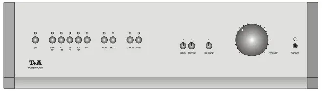
With the front panel buttons all functions of the Power Plant can be operated.
All information about the operating state of the Power Plant is displayed by the LED lamps above the buttons.
In the following sections the functions of the front panel controls and display LEDs are explained in detail.
ON
(On / Off switch)
Pressing the ON button briefly switches the device on. When the unit is switched on the green indicator above the button glows. The device switches off by a long button press.![]() Caution!
Caution!
The mains button is not a mains isolation switch. Even when the LED is not glowing parts of the machine remain connected to the mains power supply (Standby mode). The stand-by current drain is stated in the chapter entitled ‘Specification’.
If the unit is not to be used for a long period we recommend that you isolate it from the mains by pulling out the mains plug at the wall socket.
If the machine is switched off using the mains switch the energy consumption is 0 Watt. When switched off in this way, the unit cannot be switched on again using the remote control handset. If you wish to switch the unit on, first move the mains switch to the ‘1’ position.![]() The integrated amplifier can also be switched on using the source buttons. If the source device you wish to use is connected to the integrated amplifier via an E LINK cable, selecting that source switches on the amplifier automatically.
The integrated amplifier can also be switched on using the source buttons. If the source device you wish to use is connected to the integrated amplifier via an E LINK cable, selecting that source switches on the amplifier automatically.
Volume and balance
(balance setting)
The ![]() control enables you to vary the level between left and right channels, e.g. to cope with asymmetric speaker locations.
control enables you to vary the level between left and right channels, e.g. to cope with asymmetric speaker locations.
To avoid any adverse effect on the sound, the balance range is limited to +0,6 dB / -8,0 dB. It is never desirable to reduce the volume of one stereo channel to zero.
- The level of amplification is the same on both channels when the control is at the centre position.
- Rotating the control clockwise offsets the stereo centre to the right.
- Rotating the control anti-clockwise offsets the stereo centre to the left.
![]() Volume control employing a high-quality, ultra low-tolerance quadruple ALPSpotentiometer.
Volume control employing a high-quality, ultra low-tolerance quadruple ALPSpotentiometer.
Rotating the control clockwise increases the volume. Turning the control anticlockwise decreases the volume.
![]() PHONES
PHONES
(headphones socket)![]() Socket for stereo headphones with an impedance of at least 50 Ω. When listening using a headphone the speaker outputs must be turned OFF using the
Socket for stereo headphones with an impedance of at least 50 Ω. When listening using a headphone the speaker outputs must be turned OFF using the MUTE button. ![]() Continuous listening to very loud programme material via earphones or headphones can result in permanent hearing loss. You can prevent harm to
Continuous listening to very loud programme material via earphones or headphones can result in permanent hearing loss. You can prevent harm to
your own health by avoiding long periods of listening at high levels when using headphones or earphones.
Source selection Selecting the listening source
To select one of the signal sources as the listening source, push the corresponding button briefly. The LEDS above the source buttons indicate which input is currently selected for listening.![]() The audio signals of the selected source device are present at the RECORD OUT sockets and can be used for recording the programme with an audio recorder
The audio signals of the selected source device are present at the RECORD OUT sockets and can be used for recording the programme with an audio recorder
connected to these outputs.
| DISC / Music Player When the Music Player is selected as listening source the different subfunctions of this device (Radio, CD, Streaming Client) can be selected by the appropriate buttons on the front panel of the music player. | |
| A1PH | A1 / PH Line input 1 MM or MC phono preamplifier module from the accessory range. |
| A2TV | A2 / TV Line input 2 |
| A3TUN | A3 / TUNER Line input 3 |
| REC | REC Line input for Audio Recorder |
| MON (monitor switch) | Pressing the monitor button enables you to monitor the quality of a tape or CD recording (tape monitor function). Pressing the Monitor button switches the monitor function on. When the monitor function is in operation the LED above this button will glow. If no recorder is connected, or if the recorder does not support the monitor function, the music signal will be muted when you select the monitor function. If this happens, simply switch the monitor function off again. |
| MUTE | Button for switching ON and OFF the loudspaker output. |
| Tone control functions LOUDN | The integrated amplifier is equipped with a volume-dependent tone control (LOUDNESS) circuit, which compensates for the frequency-dependent sensitivity of the human ear at very low volume levels, due to the characteristics of aural physiology. Pressing the LOUDN button switches the loudness circuit on and off. The red LED above the button glows when LOUDN is switched on. |
| FLAT | The FLAT function by-passes the tone control section of the integrated amplifier and therefore disables the tone controls. The frequency response is then absolutely linear. The FLAT mode is switched on and off by pressing the FLAT button. The red LED above the button glows when FLAT mode is switched on. In FLAT mode the The LOUDNESS function is also available in FLAT mode. |
| Recessed controls | In normal use the knobs for tone and balance are recessed into the front panel. If you press any of the knobs, it projects from the front panel and can then easily be rotated. In the centre position the index marker points up, and you will feel the detent engage. When the setting is correct, push the knob back into the front panel, and it will engage in its recessed position again. |
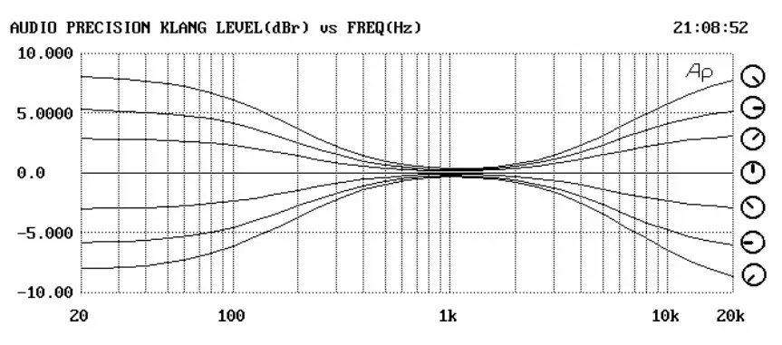
| To compensate for adverse influences on reproduction quality caused by your listening room, or imperfect loudspeaker positioning, the integrated amplifier is fitted with an active, infinitely variable tone control system. The tone controls are deliberately designed to affect only the low frequencies below 300 Hz (BASS) and the high frequencies above 4000 Hz (TREBLE); this avoids unwanted coloration in the critical mid-range sound. • When the tone controls are at centre, the frequency response is linear. • Rotating the controls clockwise increases the bass or treble. • Rotating the controls anti-clockwise reduces the bass or treble. |
Remote control handset
If a T+AMusic Player or CD Player is present in your system, the Power Plant can be controlled using the F100 / FM100 remote control of the player via the E LINK control interface.
If no Music Player oder CD-Player is present, an optional remote control set FBS100 can be obtained from your T+A dealer.
The following table shows the remote control buttons and their functions when controlling the unit.
Table: The amplifier functions of the F100 / FM100 remote control 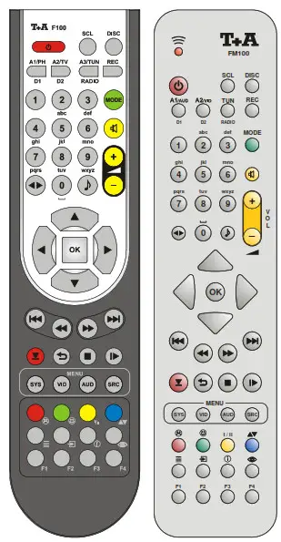
* FM100: optional accessory
| brief press: Switches the device on long press: Switches the device off |
| Direct source select button, if the integrated amplifier is switched off, selecting a source device switches the integrated amplifier on and also selects the corresponding source device. | |||
| No Music Player present | Music Player present | ||
| Brief press: | Long press: | ||
| SCL | – | Streaming Client function of the Music Player | – |
| DISC | Disc input | CD function of the Music Player | – |
| A1 / Phono | Digital-Input 1 of the Music Player | A1 / Phono Input of the Power Plant | |
| A2 / TV | Digital-Input 2 of the Music Player | A2 / TV Input of the Power Plant |
| A3 / Tuner | Radio function of the Music Player | A3 / Tuner Input of the Power Plant | |
| REC | Record | Record | |
| brief press: Switches loudspeakers on and off (MUTING) | |
| Decrease / increase the volume level The amplifier performs a small volume step first to enable a fine and precise volume control. It automatically switches to a continuous rotation of the volume control if the remote control button is pressed for a longer time. | |
| brief press: Switches LOUDNESS on and off long press: Switches tone control on and off |
Installation Using the system for the first time Safety notes
This section describes all those matters which are of fundamental importance when setting up and first using the equipment. This information is not relevant in daily use, but you should nevertheless read and note it before using the equipment for the first time.
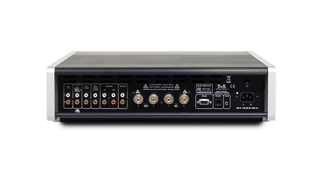
Back panel connections 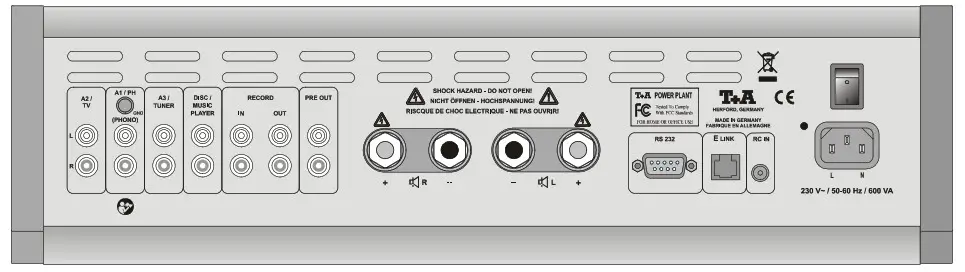
| A2 / TV | Universal line level pre-amp input for connecting any audio sources or TV sets. |
| A1 / PH | Universal pre-amplifier line input This input can be upgraded to form an input for an analogue turntable by fitting a Phono MM or Phono MC module (optional accessories). The T+A phono modules can be precisely matched to your pick up system using the adjustment switches of these modules. For further information please consult the operating manual of the phono module. |
| GND Ground terminal | The ground lead from an analogue disc player is connected here in order to avoid hum. |
| A3 / TUNER | Universal line level pre-amp input for connecting any audio sources like tuners |
| DISC / MUSIC PLAYER | Input sockets for connecting a T+A MUSIC PLAYER or a CD player. |
| RECORD | Input and output sockets for connecting devices which can record and play back (recorders). |
| PRE OUT | Pre-amplifier output for external power amplifiers or active speakers. |
| One pair of loudspeakers can be connected to the amplifier (SPEAKER The output stages are designed to cope with a minimum load of 2 Ω, but continuous operation at very high volume produces high currents in the power output stages which can lead to overheating. This in turn trips the protective circuit which switches the amplifier off automatically. Make sure that the terminals are firmly screwed down, and that no short-circuits are possible as a result of projecting cable ends or errant wire strands. stoppers can be removed from the loudspeaker terminals. The speakers can then be connected using banana plugs. The stoppers are simply a push-fit in the terminals, and can be prised out from the rear using a suitable tool such as a knife blade. | |
| RS 232 | Interface for firmware-updates and for computer-controlled operation of device functions through home-automations-systems (CRESTRON, AMX, etc.). Detailled information regarding the RS232 interface and command tables can be found in the technical download section of the T+A website http://www.taelektroakustik.de. |
| E LINK | Control output for T+A devices with E LINK inputs. |
| RC-IN (E 2000) | If no Music Player / CD Player (E-Series) is present in your system: Input socket for E2000 remotre control sensor from the remote control set FBS100. |
| Mains switch | The primary mains switch is used to isolate the machine completely from the mains supply. To operate the amplifier the primary mains switch must be moved to the ‘1’ position. |
| Mains input | This socket is for mains connection. For correct connection refer to the sections ‘INSTALLATION AND WIRING’ and ‘SAFETY NOTES’. |
Installation and wiring
Carefully unpack the unit and store the original packing material carefully. The carton and packing are specially designed for this unit and will be needed again if you wish to move the equipment at any time. Please read the safety notes in these instructions.
If the unit gets very cold (e. g. when being transported), condensation may form inside it. Please do not switch it on until it has had plenty of time to warm up to
room temperature, so that any condensation evaporates completely. Before placing the unit on a sensitive surface please check the compatibility of
the laquer and the unit’s feet on a non visible point. The quality and characteristics of the base on which your high-quality Hi-Fi equipment stands define the limits of sound quality which can be achieved. The base surface should be as heavy, rigid, hard and level as possible. The unit should be placed on a rigid, level base. When placing the unit on
resonance absorbers or anti-resonant components make sure that the stability of the unit is not reduced.
The unit should be set up in a well ventilated dry site, out of direct sunlight and away from radiators.
The unit must not be located close to heat-producing objects or devices, or anything which is heat-sensitive or highly flammable. When installing the unit on a shelf or in a cupboard it is essential to provide an adequate flow of cooling air, to ensure that the heat produced by the unit is dissipated effectively. Any heat build-up will shorten the life of the unit and could be a source of danger. Be sure to leave at least 10 cm free space above the unit for ventilation. If the system components are to be stacked then the
amplifier must be the top unit. Do not place any object on the top cover. Mains and loudspeaker cables, and also remote control leads must be kept as far away as possible from signal leads and antenna cables. Never run them over or under the unit. A complete connection diagram is shown in ‘Appendix A’ .
![]() Notes on connections:
Notes on connections:
- Be sure to push all plugs firmly into their sockets. Loose connections can cause hum and other unwanted noises.
- When you connect the input sockets of the amplifier to the output sockets on the source devices always connect like to like, i. e. ‘R’ to ‘R’ and ‘L’ to ‘L’. If you fail to heed this then the stereo channels will be reversed.
- When connecting a recorder be sure to connect the IN sockets of the recorder to the OUT sockets of the integrated amplifier, and the OUT sockets of the recorder to the IN sockets of the integrated amplifier.
- If the remote control module is installed connect the plug on the E 2000 remote control receiver (optionaly obtainable remote control set FBS100) to the socket marked RC-IN E 2000. The E LINK socket of the integrated amplifier should be connected to the E LINK socket of the source devices (see ‘Wiring diagrams’).
- To achieve maximum possible interference rejection the mains plug should be connected to the mains socket in such a way that phase is connected to the mains socket contact marked with a dot (“). The phase of the mains socket can be determined using a special meter. If you are not sure about this, please ask your specialist dealer.
We recommend the use of the T+A ‘POWER LINE’ ready-to-use mains cable and the ‘POWER BAR’ mains distribution panel which is fitted with a phase indicator as standard.
When you have completed the wiring of the system please set the volume control to a very low level before switching the system on.
Switch on the loudspeaker outlet to which your speakers are connected and switch the integrated amplifier to the listening source which you wish to hear. You should now hear the music.
If you encounter problems when setting up and using the integrated amplifier for the first time please remember that the cause is often simple, and equally
simple to eliminate. Please refer to the section of these instructions entitled ‘Trouble shooting’.
Loudspeaker and signalcables
Loudspeaker cables and signal cables (inter-connects) have a significant influence on the overall reproduction quality of your sound system, and their importance should not be under-estimated. For this reasonT+A recommends the use of high-quality cables and connectors.
Our accessory range includes a series of excellent cables and connectors whose properties are carefully matched to our speakers and electronic units, and which harmonise outstandingly well with them.
For difficult and cramped situations the T+A range also includes special-length cables and special-purpose connectors (e. g. right-angled versions) which can be used to solve almost any problem concerning connections and system location.
Mains cables and mains filters
The mains power supply provides the energy which your sound system equipment needs, but it also tends to carry interference from remote devices such as radio and computer systems. Our accessory range includes the specially shielded ‘POWER FOUR’ mains cable, ready-to-use ‘POWER LINE’ mains cable with integrated shell-type filters and the ‘POWER BAR’ mains filter distribution board which prevent electromagnetic interference from entering your Hi-Fi system. The reproduction quality of our systems can often be further improved by using these items. If you have any questions regarding cabling please refer to your specialist T+A dealer who will gladly give you comprehensive expert advice without obligation. We would also be happy to send you our comprehensive information pack on this subject.
Safety notes
All the components in this device fulfil the currently valid German and European safety norms and standards.
We ensure that our products are of consistently high quality, and meet all specifications, by checking all materials rigorously for quality, using meticulous production methods and subjecting each unit to a fully automatic computercontrolled final inspection.
For your own safety please consider it essential to read these operating instructions right through, and observe in particular the notes regarding setting up, operation and safety.
Installation
The unit must be set up in such a way that none of the connections can be touched directly (especially by children). Be sure to observe the notes and information in the section ‘Installation and Wiring’.
Loudspeaker connection terminals
The loudspeaker terminals (marked with the ![]() -symbol) can carry high voltages. Touching the terminals or any wires connected to them must be avoided.
-symbol) can carry high voltages. Touching the terminals or any wires connected to them must be avoided.
Power supply
The power supply required for this unit is printed on the mains supply socket. The unit must never be connected to a power supply which does not meet these specifications. If the unit is not to be used for a long period disconnect it from the mains supply at the wall socket.
Mains leads / Mains plug
Mains leads must be deployed in such a way that there is no danger of damage to them (e. g. through persons treading on them or from furniture). Take particular care with plugs, distribution panels and connections at the device. Unplugging the mains plug will disconnect the device from the mains for service and repair. Please make sure that the mains plug is easily accessible.
Enclosure openings
Liquid or particles must never be allowed to get inside the unit through the ventilation slots. Mains voltage is present inside the unit, and any electric shock could cause serious injury or death. Never exert undue force on mains connectors.
Protect the unit from drips and splashes of water; never place flower vases or fluid containers on the unit.
Supervision of device operation
Like any other electrical appliance this device should never be used without proper supervision. Take care to keep the unit out of the reach of small children.
Service, Damage
The case should only be opened by a qualified specialist technician. Repairs and fuse replacements should be entrusted to an authorised T+A specialist workshop. With the exception of the connections and measures described in these instructions, no work of any kind may be carried out on the device by unqualified persons.
If the unit is damaged, or if you suspect that it is not functioning correctly, immediately disconnect the mains plug at the wall socket, and ask an authorised T+Aspecialist workshop to check it.
Over voltage
The unit may be damaged by excess voltage in the power supply, the mains circuit or in aerial systems, as may occur during thunderstorms (lightning strikes) or due to static discharges.
Special power supply units and excess voltage protectors such as the T+A ‘Power Bar’ mains distribution panel offer some degree of protection from damage to equipment due to the hazards described above. However, if you require absolute security from damage due to excess voltage, the only solution is to disconnect the unit from the mains power supply and any aerial systems.
To avoid the risk of damage by overvoltages we recommend to disconnect all cables from this device and your HiFi system during thunderstorms.
All mains power supply and aerial systems to which the unit is connected must meet all applicable safety regulations and must be installed by an approved electrical installer.![]() Note: Many insurance companies offer lightning damage insurance for electrical equipment as part of their household insurance service.
Note: Many insurance companies offer lightning damage insurance for electrical equipment as part of their household insurance service.
Approved usage
This device is designed exclusively for reproducing sound and/or pictures in the domestic environment. It is to be used in a dry indoor room which meets all the recommendations stated in these instructions.
Where the equipment is to be used for other purposes, especially in the medical field or any field in which safety is an issue, it is essential to establish the unit’s suitability for this purpose with the manufacturer, and to obtain prior written approval for this usage.
Approval and conformity with EC directives
In its original condition the unit meets all currently valid European regulations. It is approved for use as stipulated within the EC.
By attaching the CE symbol to the unit T+A declares its conformity with the EC directives 89/336/EEC, amended by 91/263/EEC, amended by 93/68/EEC, and
also 73/23/EEC, amended by 93/68/EEC and the national laws based on those directives.
The original, unaltered factory serial number must be present on the outside of the unit and must be clearly legible! The serial number is a constituent part of our conformity declaration and therefore of the approval for operation of the device.
The serial numbers on the unit and in the original T+Adocumentation supplied with it (in particular the inspection and guarantee certificates), must not be removed or modified, and must correspond.
Infringing any of these conditions invalidates T+A conformity and approval, and the unit may not be operated within the EC. Improper use of the equipment makes the user liable to penalty under current EC and national laws.
Any modifications or repairs to the unit, or any other intervention by a workshop or other third party not authorised byT+A, invalidates the approval and operational permit for the equipment. Only genuine T+A accessories may be connected to the unit, or such auxiliary devices which are themselves approved and fulfil all currently valid legal
requirements. When used in conjunction with auxiliary devices or as part of a system this unit may only be used for the purposes stated in the section ‘Approved usage’.
Disposing of this product![]() The only permissible method of disposing of this product is to take it to your local collection centre for electrical waste.
The only permissible method of disposing of this product is to take it to your local collection centre for electrical waste.
Care of the unit: Disconnect the mains plug at the wall socket before cleaning the case.
The surfaces of the case should be wiped clean with a soft, dry cloth only.
Never use solvent-based or abrasive cleaners!
Before switching the unit on again, check that there are no short-circuits at the connections, and that all cables are plugged in correctly.
FCC Information to the user![]() (for use in the United States of America only) Class B digital device – instructions:
(for use in the United States of America only) Class B digital device – instructions:
Note: This equipment has been tested and found to comply with the limits for a Class B digital device, pursuant to Part 15 of the FCC Rules. These limits are designed to provide reasonable protection against harmful interference in a residential installation. This equipment generates, uses and can radiate radio frequency energy and, if not installed and used in accordance with the instructions, may cause harmful interference to radio communications. However, there is no guarantee that interference will not occur in a particular installation. If this equipment does cause harmful interference to radio or television reception, which can be determined by turning the equipment off and on, the user is encouraged to try to correct the interference by one or more of the following measures:
– Reorient or relocate the receiving antenna.
– Increase the separation between the equipment and receiver.
– Connect the equipment into an outlet on a circuit different form that to which the receiver is connected.
– Consult the dealer or an experienced radio/TV technician for help.
Trouble shooting
Many problems have a simple cause and a correspondingly simple solution. The following section describes a few difficulties you may encounter, and the measures you need to take to cure them. If you find it impossible to solve a problem with the help of these notes please disconnect the unit from the mains and ask your authorised T+A specialist dealer for advice.
| Machine does not switch on (green LED does not light up). | Cause 1: Mains lead not plugged in correctly. Remedy: Check connection, push connector in firmly. |
| Cause 2: Mains fuse burned out. Remedy: Have the mains fuse replaced by an authorised specialist workshop. The rating of the replacement fuse must agree with the specification printed on the unit. | |
| Cause 3: Mains switch on the back panel not switched on. Remedy: Switch the mains switch on. | |
| The unit does not respond to commands. | Cause: Static discharge or powerful interference (e. g. lightning) have corrupted the processor memory. Remedy: Disconnect mains plug. wait about 1 minute and re-connect. Switch unit on again. |
| Machine responds correctly to manual operation of the buttons, but does not respond to remote control commands. | Cause 1: E LINK cable between Power Plant and Music Player is not property connected. Remedy: Please check and properly install the E UNK cable |
| Cause 2: Incorrectly inserted batteries or flat batteries in the remote control handset. Remedy: Re-install batteries correctly or fit new ones. | |
| Cause 3: No Music Player / CD Player present. Remedy: Please install the remote control set FBS100 available from your WI dealer. | |
| The source devices connected to the system does not respond to remote control commands. | Cause 1: The unit you are trying to control is not selected as source device. i. e. the commands from the remote control handset are being passed to a different source device. Remedy: Press The corresponding source button on the remote control handset and try again. |
| Cause 2: The source device is not connected via an E UNK cable. Remedy: Complete the connection as shown in the wiring diagram. | |
| Loud humming noise from the loudspeakers. | Cause: Poor contact between the Cinch plugs and sockets, or a faulty Cinch cable. Remedy: Please check all connections and cables thoroughly. |
| No output signal at the | Cause 1: The PROTECTION circuit has tripped due to overheating or overloading. Remedy: Reduce volume and wait for about 20 seconds. If the unit does not switch on again automatically, it has become too hot and should be left switched off for a few minutes to cool down. Cause 2: Short-circuit in the speaker leads, e. g. stray wire ends touching at the speaker terminals, or mechanical damage to the cables. Remedy: Check speaker leads and terminals, twist wire ends together neatly, replace damaged cables. Cause 3: Overloading due to poor earth contact. Remedy: Disconnect input cable and wait to see if the amplifier switches back on again; if so, check the input lead and replace if necessary. |
| Unit switches off repeatedly at fairly high volume levels | Cause 1: Overheating due to heat build-up. Remedy: Set up the unit in such a way that an unobstructed flow of cooling air is guaranteed. Cause 2: Overheating through insufficient loudspeaker impedance. Remedy: Use only loudspeakers of at least 4 Ω impedance (DIN rating). That means a minimum impedance of > 3.2 Ω. |
| Flat sound image, insufficient bass response. | Cause: The loudspeaker cables are connected with reversed polarity. Remedy: Check the speaker connections at the loudspeakers and at the integrated amplifier’s speaker terminals; correct if necessary. |
Glossary
| AUX | Universal pre-amplifier input (AUX = auxiliary input) for connecting high-level signal sources (i.e. signal sources with an output level between 0.25 V and 3,5 V). |
| Balance | The balance control provides infinite adjustment of level between right and left channels (shift of stereo centre), e. g. to compensate for asymmetric speaker positioning. To avoid any adverse effect on the sound, the balance range is limited to +6 dB / -8 dB. It is never desirable to reduce the volume of one stereo channel to zero. |
| dB | The unit of measurement for electrical levels is the deci Bel (dB). |
| E LINK | Control interface for remote control of T+A systems. The CD player / Music Player receives the infra-red remote control signals and passes then on to the power amplifier and to the source devices. |
| FLAT | In FLAT mode the signals pass along the shortest possible signal paths within the unit. All sub-assemblies which are not absolutely essential (e. g. the tone controls) are by-passed by means of high-quality gold-contact relays in this mode. The frequency response and phase response of the unit are absolutely linear in this mode of operation. This means that the FLAT setting provides the most faithful reproduction and the highest possible quality, and it should always be selected if the tone controls are in the centre position in any case. |
| Loudness | A volume-dependent tone control (Loudness) circuit which compensates for the frequency-dependent sensitivity of the human ear at very low volume levels. At very high volumes the loudness circuit has absolutely no effect, but as volume is reduced the bass and upper treble are lifted, in order to compensate for the reduction in sensitivity of the human auditory system at low levels. |
| MC | Some analogue turntables are fitted with dynamic sound pick-up systems (MC = Moving Coil). The amplifier can be fitted with an optional high-quality MC phono pre-amplifier module whose input impedance and input sensitivity can be adjusted to match all currently available dynamic pick-up systems. |
| MIM | Some analogue turntables are fitted with magnetic sound pick-up systems (MM = Moving Magnet). The amplifier can be fitted with an optional high-quality MM phono pre-amplifier module whose input impedance and input sensitivity can be adjusted to match all currently available magnetic pick-up systems. |
| Source device | The term source device refers to those elements of a Hi-Fi system which provide a sound signal, such as tuners, CD players, recorders etc. (signal sources). We have to differentiate between listening sources and recording sources. – A listening source is the device to which you are currently listening. This device can be remote-controlled. – A recording source is a source from which a recording can be made using a recorder (TAPE). A recording source cannot be remote-controlled. |
| Update / Upgrade | This T+A unit can be kept up to date with the current state of development by fitting an update or upgrade. – An Update expands the unit’s operating facilities by the installation of a new program memory. – An Upgrade involves the installation of replacement sub-assemblies or auxiliary modules. The installation or conversion work is carried out by your specialistT+A dealer. |
| Volume control | The amplifier features a two-stage volume control which enables the unit to work at a high level of amplification in the input stage of the pre-amplifier, without risking overloading the pre-amplifier. This is the responsibility of the first volume control. In the subsequent stages of signal processing the amplifier has a higher-level signal to handle, and this in turn significantly reduces hiss and crossover distortion where the signal passes through zero. The second volume control reduces any hiss generated in the pre-amplifier at low levels directly before the output stage. |
Anhang / Appendix A
Verwendung von Bananensteckern siehe Kap. ‘Anschlusselemente’.
Use of banana plugs: see the section entitled ‘Back panel connections’.
Anschluss-Schema / Wiring diagram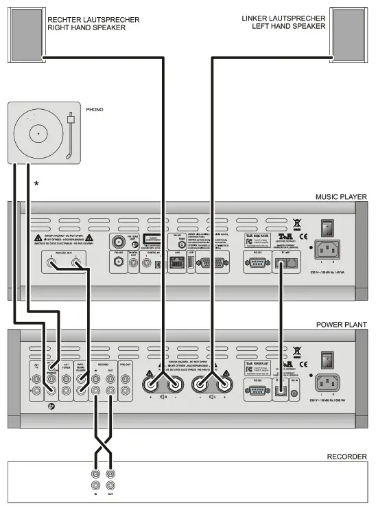
* Hinweis: Für den Anschluss von Plattenspielern kann der Power Plant mit Hilfe der als optional lieferbaren PhonoverstärkerEinbaumodule PHE MM (Magnet System) oder PHE MC (Moving Coil System) aufgerüstet werden. * Note: For the operation with phono turntables an optinal phono pre-amplifier module can be installed in your Power Plant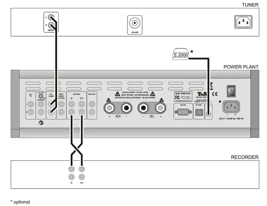
Anhang / Annex B
Technische Daten / Technical Specifications
| Nennleistung pro Kanal 8 L Output Power (RMS) per channel 4 L | 2 x 140 W 2 x 240 W |
| Impulsleistung 8 L Output Power (Peak) 4 L | 2 x 210 W 2 x 380 W |
| Frequenzgang / Frequency response | 1 Hz – 60 kHz (+0/-3dB) |
| Klirrfaktor / THD | < 0.005 % |
| Intermodulation | < 0.005 % |
| Kanaltrennung / Channel separation | > 80 dB |
| Eingänge / Inputs | 5 x Hochpegel / line 250 mV / 20 kL |
| Ausgänge / Outputs | Vorverstärkerausgang, Kopfhörerausgang, Tapeausgang Pre amplifier, Headphone, Tape record output |
| Netzanschluss / PWR requirement | 230 V version | 220 / 230 V~, 50-60 Hz |
| 115 V version | 110 / 115 V~, 50-60 Hz | |
| Leistungsaufnahme | max. | 600 W |
| Power con-sumption | Standby | 1 W |
| Zum Lieferumfang gehören Supplied standard accessories | · Netzkabel / Power cord · Betriebsanleitung / User manual | |
| Erweiterungen und Zubehör Optional accessories | · Fernbedienungsset / Remote Control FBS100 · Fernbedienung / Remote Control FM100 · MM & MC-Phono Modul · Signal- & Lautsprecherkabel / Signal & loudspeaker cables | |
Technische Änderungen vorbehalten / We reserve the right to alter specifications
T+A elektroakustik GmbH & Co. KG
Herford
Deutschland * Germany


