POTTER UD-2000 Digital Alarm Communicator
Features
- Allows for communication to Monitoring Station
- Communicates using SIA-DCS or Ademco Contact ID Protocols
- For use with IPA, AFC, and ARC series Addressable Panels and PFC-4064 Conventional Panel
- Status LEDs indicate operation of DACT card
- Installs with ease behind main panel LCD display via User Interface bracket
- Device address is set internally to address 1
- Includes two (2) RJ45 phone cords
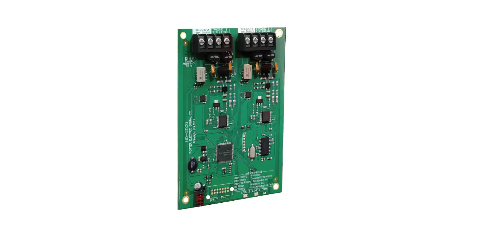
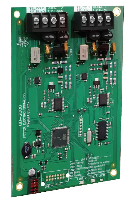
Description
The UD-2000 Digital Alarm Communicator Transmitter (DACT) provides for up to two (2) phone lines for communication to a monitoring station. The UD-2000 communicates using the SIA-DCS or Ademco Contact ID protocols. When enabled, the DACT automatically monitors each phone line or voltage and has the ability to seize the line and connect with a remote receiver. Once the communication is complete, the DACT will hang up. The DACT is provided with terminal blocks for each phone line and two RJ45 cords. In order for the DACT to work properly, it must be installed on a plain old telephone service (POTS) line or equivalent deemed by the authority having jurisdiction. The DACT must be installed before any other equipment to ensure it can seize the phone line. Phone lines are high voltage and should be run in a separate conduit from other circuits. The wire conductors connecting the DACT to the phone system should be 26 AWG or larger.
Technical Specifications
| Operating Voltage | 22.0-24.0V |
| Standby Current | 16ma |
| alarm Current | 23ma |
| Max UD-2000s per panel | 1 |
| Dimensions | 4”W * 6”H * 1-5/8”D |
| Operating Tempuratures | 0°C – 49°C (32°F- 120°F) |
| Operating Humidity Range | 10% – 93% @ 30°C (86°F) (non-condensing) |
| Mounting Options | In FaCp Behind keypad |
| Shipping Weight | 0.47 lbs |
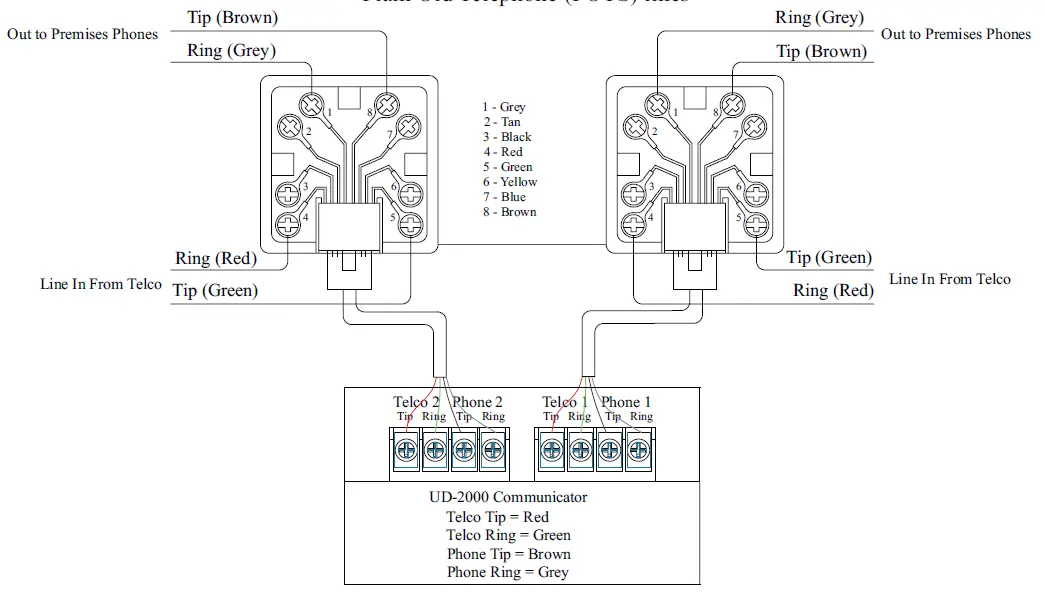
RJ31X Phone Jack to UD-2000
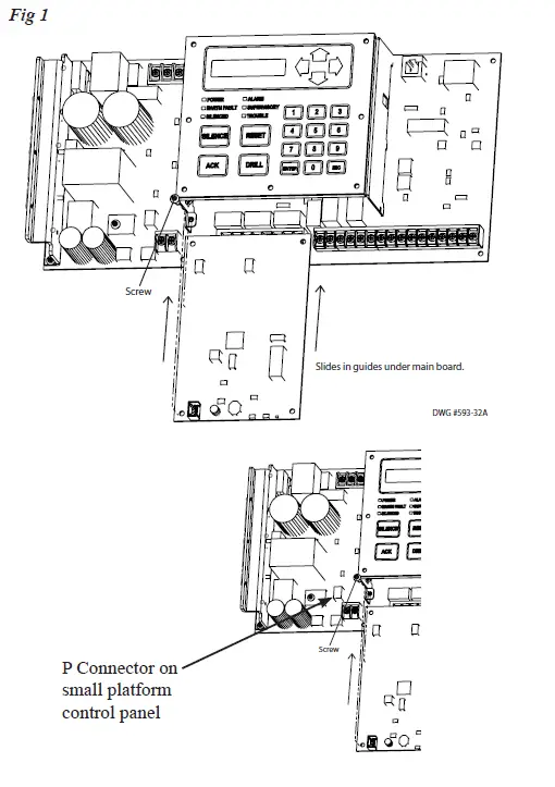
Installation
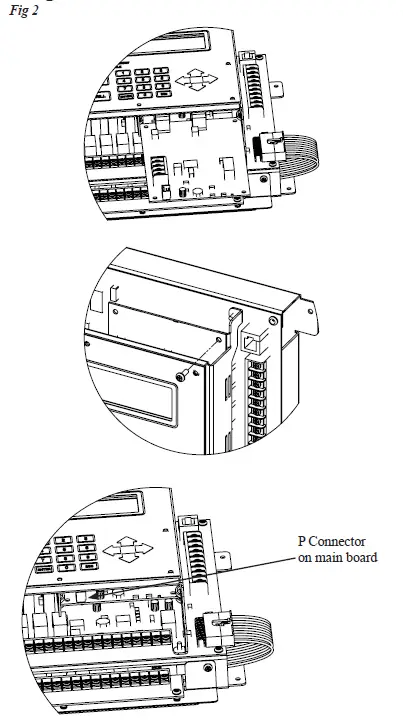
The UD-2000 DACT is connected to the control panel using the provided four-wire cable connection (P/N 5210514) between P4 and UD-2000 P1. The connection is power limited and supervised.
- Power system down.
- Slide the UD-2000 into the card guides located under the User Interface bracket.
- Secure the UD-2000 to the User Interface bracket using the provided #6-32×3/8” screw
- Install the provided four-wire conductor jumper between UD-2000 P1 and P4.
UD-2000 DACT Installation on Small Platform Panel
UD-2000 DACT Installation on Large Platform Panel
Ordering Information
| Model | Description | Stock No. |
| UD-2000 | Digital Alarm Communicator | 3992769 |


