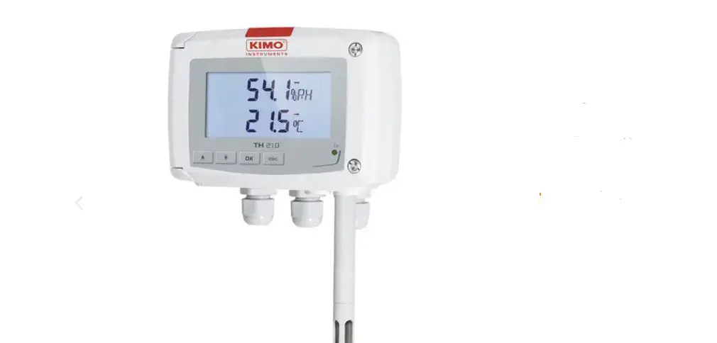
sauermann TH 110 Humidity and Temperature Sensor
Humidity and temperature transmitter
- Operating temperature, protection of the instruments and information about storage.
- Conditions of use °C/%RH/m from -10 to +50 °C in non-condensing conditions.
- From 0 to 2000 m. Protection: IP65(2) or IP20(1)
- Storage temperature: from -10 to +70 °C.
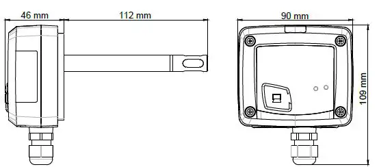
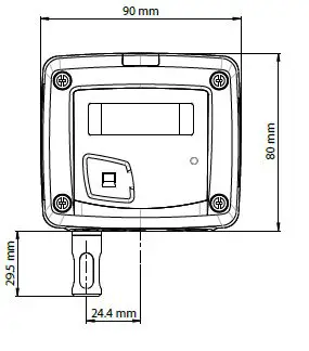
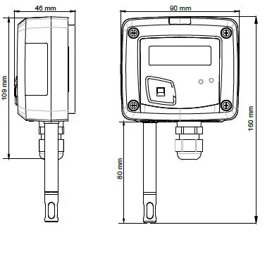
Dimensions
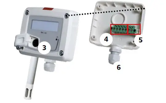
Duct model
Ambient model
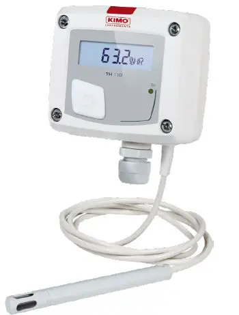
Remote model
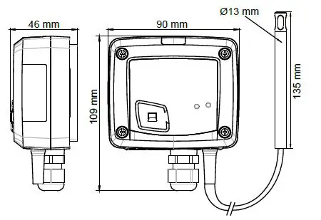
Standard model
Symbols used
For your safety and in order to avoid any damage of the device the notes preceded by the following symbol

The following symbol show the information notes indicated after this symbol

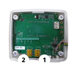
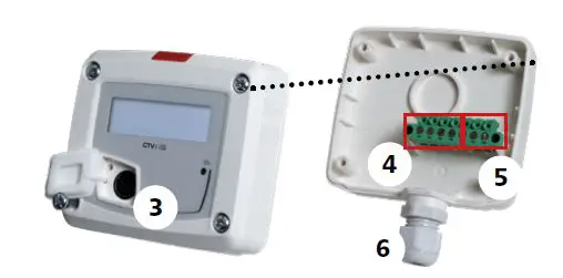
Connections
Inside the front housing
Removable front face and Fixed back housing
Standard model
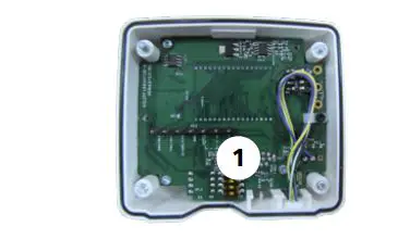
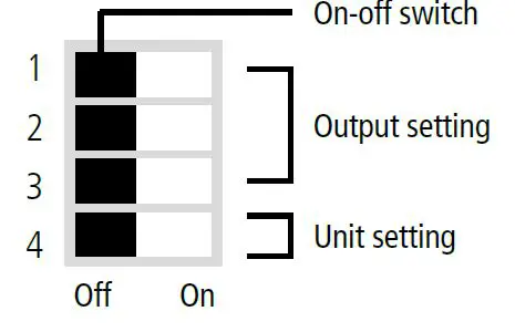
- Switch 1 (S1)
- Switch 2 (S2)
- LCC-S software connection.
- Output terminal block.
- Power supply terminal block.
- Cable gland.
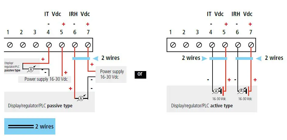
Electrical connections as per NFC15100 standard
This connection must be made by a qualified and trained technician. To make the connection, the transmitter must NOT BE ENERGIZED For TH 110-AOS, TH 110-ANS, TH 110-AOD, TH 100-AND, TH 110-AOA, TH 110-ANA TH 110-ANES, TH 110-AOES models with
output 0-10 V – active.
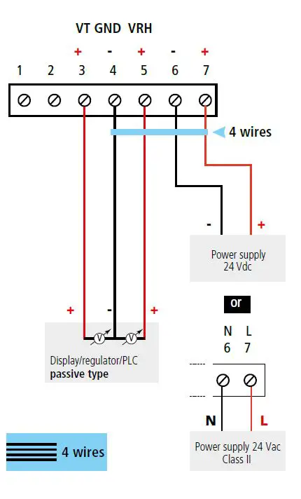
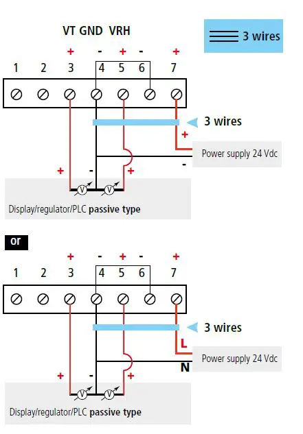 For TH 110-POS, TH 110-PNS, TH 110-POD, TH 110-PND, TH 110-POA, TH 110-PNA, TH 110-PNES models with output 4-20 mA – passive.
Settings and use of the transmitter
Configuration
To configure the transmitter, it must not be energized. Then, you can make the settings required, with the DIP switches.When the transmitter is configured, you can power it up. Please follow carefully the combinations beside with the DIP switch. If the combination is wrongly done, the following message will appear on the display of the transmitter CONF ERROR. In that case, you will have to unplug the transmitter place the DIP switches correctly and then power the transmitter up.
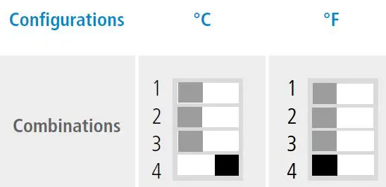
Units setting active switch
To set a unit of measurement, put the on off switch 4 of the units as shown below.
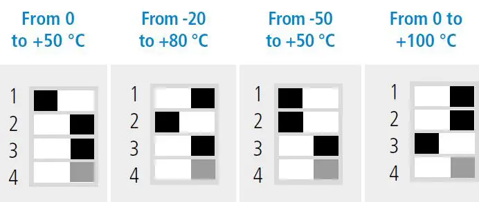
Outputs setting active switch
To set an output, put the on-off switches 1, 2 and 3 of the measuring ranges as shown below.
Configuration via LCC-S software option
It is possible to configure intermediate ranges, an offset. Example for a 0-100 °C transmitter, minimum delta is 20 °C. The instrument can be configured from 0 to +20 °C or from -10 to +10 °C. In order to compensate a possible drift of the sensor, it is possible to add an offset to the displayed value by the TH 110 transmitter: it shows 48% RH, a standard instrument shows 45% RH. It is then possible, via the software, to integrate an offset of -3 to the displayed value by the TH 110 instrument. The configuration of the parameters can be done either with the DIP switch or via software you can not combine both solutions.
PC configuration
Connect the cable of the LCC-S to the connection of the transmitter
 Active switch (S1)
Mounting
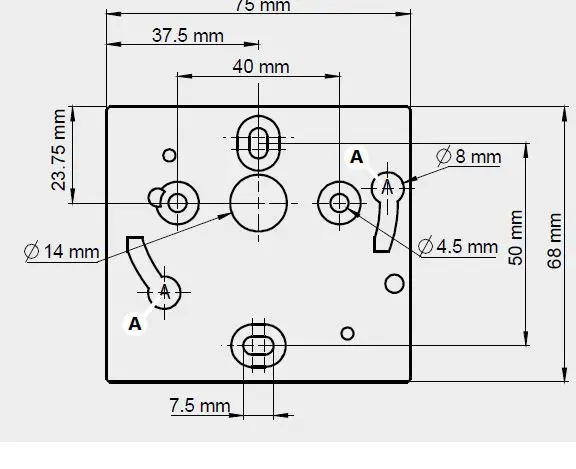
To mount the transmitter, mount the ABS plate on the wall drilling: Ø 6 mm, screws and pins are supplied. Insert the transmitter on the fixing plate A on the drawing beside. Rotate the housing in clockwise direction until you hear a click which confirms that the transmitter is correctly installed.
Maintenance
Please avoid any aggressive solvent. Please protect the transmitter and its probes from any cleaning product containing formalin, that may be used forcleaning rooms or ducts.
Precautions for use
please always use the device in accordance with its intended use and within parameters described in the technical features in order not to compromise the protection ensured by the device.


