![]() SILEN I
SILEN I
SILEN S
SILEN S2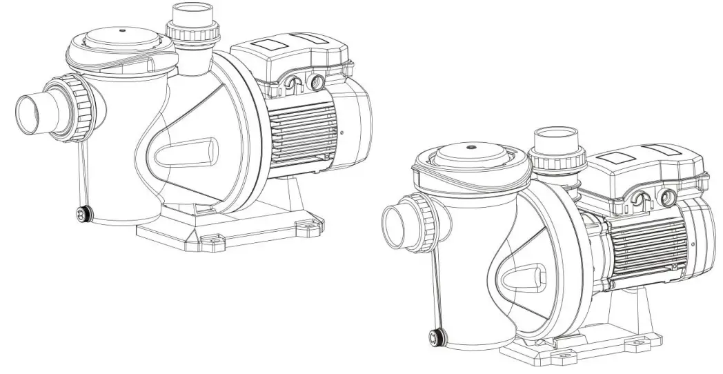 Instruction manual
(Translation from the original Spanish)
UKCA CERTIFICATE OF CONFORMITY
EVIDENCE OF CONFORMITY
We declare, under our responsibility, that the products in this manual comply with the following directives and standards:
– Supply of Machinery (Safety) Regulations 2008: Standard BS 809 and BS 60204-1
– Electromagnetic Compatibility Regulations 2016: Standard BS 61000-6-1 and BS 61000-6-3.
– Electrical Equipment (Safety) Regulations 2016: Standard BS 60335-1 and BS 60335-2-41.
– The Ecodesign for Energy-Related Products and Energy Information (Amendment) (EU Exit) Regulations 2019:
Standard BS 60034-30.
– The Restriction of the Use of Certain Hazardous Substances in Electrical and Electronic Equipment Regulations 2012. Standard BS 50581.
Banyoles, January 8th 2021
 Josep Unyó (Technical Manager) ESPA 2025, SL
Ctra. de Mieres, s/n – 17820 Banyoles Girona – Spain
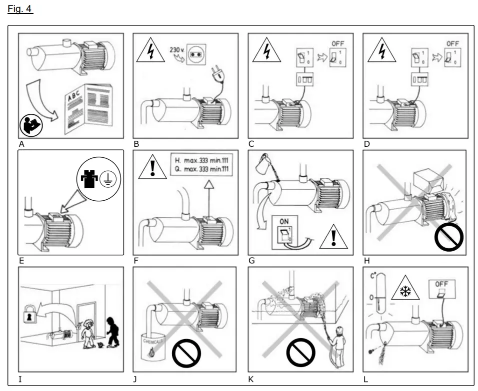
Damage prevention and safety instructions (See figure 4)
| A | Warning! Observe limitations of use. |
| 3 | The name plate voltage must be the same as the mains voltage. |
| C | Connect the pump to the mains via an omnipolar switch with at least a 3 mm opening between contacts. Install a high-sensitivity differential switch (0.03A) as extra protection against lethal electric shocks. |
| 0 | If the supply cord is damaged, it must be replaced by an A.T.S. |
| E | Connect the pump to the ground. |
| F | Use pump only within performance limits indicated on the name plate. |
| G | Remember to prime pump. |
| H | Check for motor self-ventilation. |
| I | This apparatus may be used by children 8 years or older and persons with reduced physical, sensory or mental capacities, or lacking experience and knowledge, if they are supervised or receive adequate training on the safe use of the apparatus and understand the dangers. Children should not be allowed to play with the apparatus. Children should not perform the ordinary cleaning and maintenance tasks without supervision. |
| J | Be careful with hazardous liquids and environments. |
| K | Caution! Look out for accidental leaks. Do not expose pump to bad weather. |
| L | Caution! Avoid icing. Cut out power supply before servicing pump. |
Safety precautions
This symbol ![]()
![]() together with one of the following words “Danger” or “Warning” indicates the risk level deriving from failure to observe the prescribed safety precautions:
together with one of the following words “Danger” or “Warning” indicates the risk level deriving from failure to observe the prescribed safety precautions:![]() DANGER risk of electric shock
DANGER risk of electric shock
Warns that failure to observe the pre cautions involves a risk of electric shock.![]() DANGER Warns that failure to observe the pre cautions involves a risk of damage to persons and/or things.
DANGER Warns that failure to observe the pre cautions involves a risk of damage to persons and/or things.![]() WARNING Warns that failure to observe the pre cautions involves the risk of damaging the pump and/or the facility
WARNING Warns that failure to observe the pre cautions involves the risk of damaging the pump and/or the facility
GENERAL INFORMATION
Please observe the following instructions to achieve the best pump performance possible and a trouble free installation.![]() Read these instructions before installing the pump.
Read these instructions before installing the pump.
Save them for future reference.
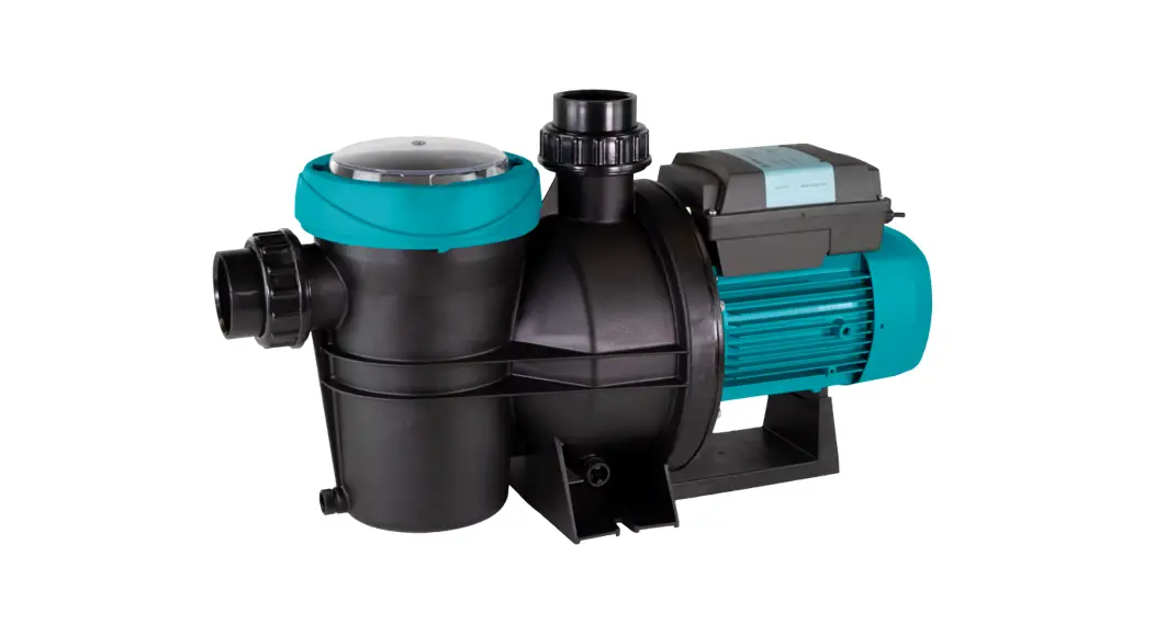
These are single cell centrifugal pumps with built-in filter elements, especially designed for prefiltering and recirculation of water in swimming pools.
These pumps are designed to operate with clean water, free from particles in suspension and with a maximum temperature of 40ºC.![]() Correct pump operation is assured providing the instructions on electrical connection, installation and use are strictly adhered to.
Correct pump operation is assured providing the instructions on electrical connection, installation and use are strictly adhered to.![]() Failure to adhere to the instructions can result in premature failure of the pump and voiding of the warranty.
Failure to adhere to the instructions can result in premature failure of the pump and voiding of the warranty.
HANDLING
The pumps are supplied suitably packaged to prevent damage in transit. Before unpacking, checkthat the packaging has not been damaged or deformed,![]() Lift and handle the product with care and withthe right tools.
Lift and handle the product with care and withthe right tools.
INSTALLATION
The installation of these electric pumps is only permitted in swimming pools or ponds that comply with standards IEC 60364-7-702 and/or the national regulations of the country in which the product is to be installed.
3.1. Fixing
The pump should be installed on a solid, horizontal base, secured by screws or bolts and using the existing holes in the mount.
The pump should be protected from possible flooding and receive dry ventilation.
3.2. Suction pipe assembly
The pumps must be installed at least two meters from the wall of the pool, and at the same height as the level of the water, or if possible, below. The end of the suction pipe must always remain at least 30 cm below the water level.
The suction pipe, if longer than 7 meters, must be of the same or greater diameter than the pump inlet and installed in an upward inclination to prevent trapped air pockets forming. If the pump is required to perform a suction lift, to avoid unnecessary losses of head on the discharge side, the pump should be installed as close as possible to the water. It is not advisable to install the pump at more than 3m geometrical height from the water level.
3.3. Discharge pipe assembly
It is recommended to use pipes with a diameter equal or greater than the pump outlet. This will reduce loss of head caused by friction in longer pipe runs. Pipework must be supported and their weight must not rest on the pump.
3.4. Electrical connection
The electrical installation must have a multipole isolator with minimum 3 mm contact openings, The protection of the system will be based on a differential switch (Δfn = 30 mA)
The power cable must correspond at least to the type H07 RN-F (according to 60245 IEC 66) and having terminals.
The connection and its dimensioning must be performed by a qualified installer according to the needs of the facility and following the regulations in force in each country.
The power supply socket for the apparatus must be at least 3.5m from the pool.![]() Single-phase motors have thermal protection.
Single-phase motors have thermal protection.
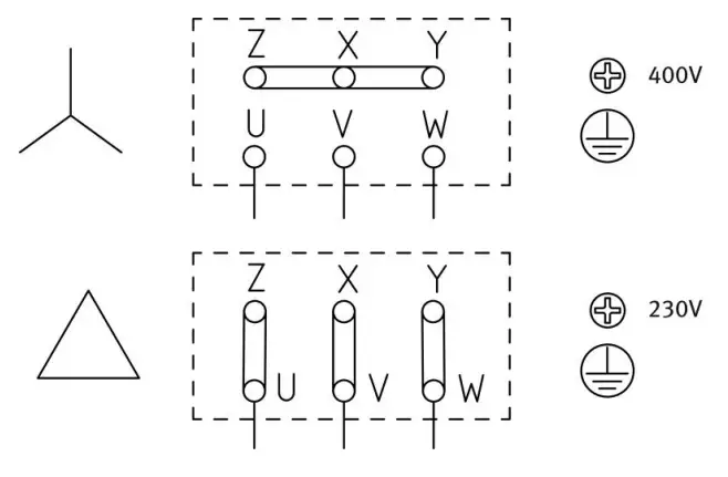
All of three phase motor pumps do not incorporate this protection. They must be connected to a motor-protective circuit breaker that can be adjusted manually. Set the circuit breaker according to the current given in the rating plate plus 10%. Follow instructions given on fig.1 for correct electrical connection.
3.5. Pre-start checks
Ensure the voltage and frequency of the supply corresponds to the values indicated on the electrical data label.
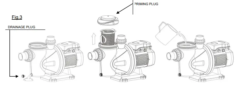
Ensure that the pump shaft is rotating freely. Fill the pump body with water through the filter cover to the bottom level of the suction line. Check all joints and connections for leaks. Set the prefilter cover back in place and screw it to a suitable tightness. THIS PUMP MUST NEVER BE DRY RUN.
STARTING
Ensure all valves in the pipework are open.
Connect power supply. There will be a delay before water appears at the end of the discharge pipe. Viewings from the fan ensure that the rotation of the motor is clockwise. On three phase pumps the motor may rotate anticlockwise. If this is happening, the flow will be lower than expected. To rectify this situation the two supply phases need to be reversed. Ensure that the absorbed current is the same or lower than the maximum shown on the name plate. Adjust the thermal relay if is necessary. If the pump fails to operate refer to the possible faults, causes and solutions list for assistance.
MAINTENANCE
Under normal conditions these pumps require no special or planned maintenance.
Clean the pump with a damp cloth without using harsh products.![]() If the pump is not to be operated for a long period it is recommended to remove it from the installation, drain down and store in a dry, well ventilated place.
If the pump is not to be operated for a long period it is recommended to remove it from the installation, drain down and store in a dry, well ventilated place.
ATTENTION: In the event of faults or damage occurring to the pump, repairs should only be carried out by an authorised service agent. The Official Technical Services list is in www.espa.com.
DISPOSING OF THE PRODUCT
When the pump is eventually disposed of, please note that it contains no toxic or polluting material.
All main components are material identified to allow selective disposal.
This product or parts of it must be disposed of in an environmentally sound way, use the waste collection service. If this is not possible, contact the nearest ESPA service workshop.
PLATE SHOWING CHARACTERISTICS
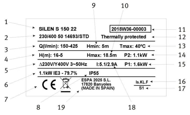
DESCRIPTION
| 1 | Item reference |
| 2 | Voltage + frequency + item specifications |
| 3 | Flow |
| 4 | Pressure |
| 5 | Nominal voltage, no. stages, alternate current symbol and frequency |
| 6 | Energy efficiency index (Three-phase model) |
| 7 | Capacitor (Single-phase model) |
| 8 | EC mark |
| 9 | Humidity protection level |
| 10 | Minimum working pressure |
| 11 | Maximum pressure |
| 12 | Year and week of manufacture + Pump serial no. |
| 13 | Thermal protection incorporated indicator |
| 14 | Max. liquid temperature |
| 15 | Motor max. nominal output (P2) |
| 16 | Electric pump unit absorbed power(P1) |
| 17 | Designated motor insulation |
| 18 | Continuous operation symbol |
| 19 | Maximum nominal intensity at nominal voltage |
| 20 | Name and address of vendor responsible for the product |
POSSIBLE FAULTS, CAUSES AND SOLUTIONS
- Pump does not prime.
- Pump supplies scant flow.
- Pump noisy.
- Pump does not start.
- Motor makes sound but does no start.
| 1 | 2 | 3 | 4 | 5 | POSSIBLE PROBLEM | SOLUTIONS |
| X | X | Air entry trough suction line | Verify condition of connectors and gaskets of suction line | |||
| X | Inadequate airtightness of filter cover | Clean the filter cover and verify con- diction of rubber gasket | ||||
| X | X | Motor turning direction reversed | Reverse 2 phases of the supply | |||
| X | Defective mechanical seal | Change mechanical seal | ||||
| X | X | Excessive suction height | Excessive suction height | |||
| X | X | X | Incorrect voltage | Verify the voltage specified on the nameplate and that of the mains | ||
| X | No water in prefilter | Fill prefilter with water | ||||
| X | Suctioning out of water | Set suction in correct position | ||||
| X | Filter clogged | Clean filter | ||||
| X | X | Diameter of suction line smaller than required | Correctly dimension suction line | |||
| X | Discharge clogged | Inspect filter and discharge line | ||||
| X | Incorrect pump attachment | Attach pump correctly | ||||
| X | Foreign body in pump | Clean pump and inspect its filter | ||||
| X | Thermal relay tripped | Reset thermal relay | ||||
| X | Lack of power | Reset the fuses | ||||
| X | Motor blocked | Remove the motor and call the Technical Service |
TECHNICAL DATA
Liquid temperature: ……………………. 4ºC – 40ºC
Ambient temperature: ………………… 0ºC – 40ºC
Storage temperature: ………………. -10ºC – 50ºC
Ambient relative humidity, max.: …………… 95% Motor class I.
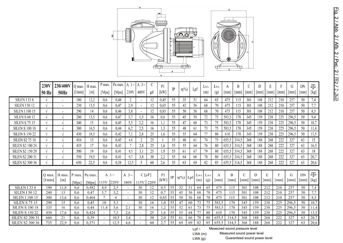
Other data see Figure 2.
List of main components

| 1 | Pump casing |
| 2 | Suction cover |
| 3 | Diffuser |
| 4 | Impeller |
| 5 | Interstage casing |
| 6 | Capacitor |
| 7 | Foot |
| 8 | Mechanical seal |
| 9 | Bearing |
| 10 | Stator |
| 11 | Motor shaft |
| 12 | Fan cover |
| 13 | Fan |
Fig.1
SINGLE PHASE SUPPLY
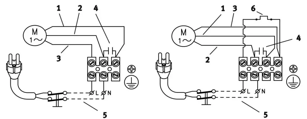
| 1 | RED |
| 2 | WHITE |
| 3 | BLACK |
| 4 | CAPACITOR |
| 5 | LINE |
| 6 | MOTOR RELAY |
THREE PHASE SUPPLY
ESPA 2025, S.L.
C/ Mieres, s/n — 17820 BANYOLES GIRONA — SPAIN
www.espa.com  http://www.espa.com


