
![]()
FerIT® Node and Solar Node
User Guide
Document No. FN-20
Date: 8/27/2020
Version: 1.0
FerIT® Node and Solar Node – User Guide
Copyright © 2020 Rubicon Water
RUBICON logo, BayDrive, BladeMeter, BladeValve, CableDrive, Confluent, FarmConnect, FerIT, FlumeGate, FlumeMeter, MicronLevel, PikoMeter, SCADAConnect, SlipGate, SlipMeter, SolarDrive, Sonaray, TCC and Total Channel Control are trademarks and service marks, or registered trademarks and service marks of Rubicon Water or its affiliates in Australia, the United States of America and other jurisdictions. Systems, components, methodologies and software supplied by Rubicon Water may be the subject of patent and design rights in Australia and elsewhere.
Introduction
About Rubicon Water
Our mission is to deliver and maintain innovative technology solutions that increase water use efficiency and improve supply reliability to support sustainable global food and fibre production.
Rubicon’s vision is to be the market leader in delivering cost-effective, reliable and practical water management solutions to assist the world’s rural water and agribusiness managers in maximising the beneficial use of water.
Purpose of this Manual
The purpose of this manual is to describe characteristics and installation requirements of the Rubicon FerIT® Node and FerIT® Solar Node.
Any deviation from Rubicon approved procedures and materials may be detrimental to the functionality and structural integrity of the FerIT and associated products. The operator may not in any way change or modify this procedure and or materials without written permission from Rubicon.
Support and Training
Rubicon Water provides support and training services that help you get the most out of your product. Contact Rubicon Support for details.
Contact Us
Contact your local Rubicon office for information. See the Rubicon Water website for contact details.
About the FerIT
The FerIT is a data monitoring, control, and communication device for on-farm applications. It is compatible with Rubicon’s FarmConnect range of products and can be used with Rubicon FarmConnect software to remotely monitor and control both Rubicon products and third-party devices. It is designed to be rugged, easy to install, and easy to use.
The FerIT comes in two configurations:
- The FerIT Node is a low-powered data collection device designed for monitoring applications.
- The FerIT Solar Node is a solar powered device intended for high-power actuation and control. It
contains an integrated FerIT Node and adds the ability to drive devices such as Rubicon’s BladeMeter and BayDrive.
Both the FerIT Node and the FerIT Solar Node can be supplied with either a LORA or a P400 radio connection for communication with a Rubicon Gateway.
FerIT Specifications
General
| Controller | |
| Type | ARM Cortex M4F 64Mhz |
| Features | RTOS, Data Logging, Internal Temperature |
| Short Range Radio | |
| Operating Frequency | 2400 MHz |
| Range | Up to 50m |
| Data Rate | ≥ 100kbps |
| Antenna | Internal |
| Long Range Radio | |
| See options in Long Range Radio Variants | |
| Compliance and Certification | |
| Australia | RCM: Medium risk device (battery powered radio emitting device) |
| USA | FCC: Part 15 Class B, Part 18 regulations (Industrial equipment) |
Environmental
| Operating Range | |
| Temperature | -40 to 60 °C |
| External Connectors, Cables | |
| Dust and Water Ingress | IP66 |
| Enclosures | |
| Shock protection | IEC IK07 |
| Material | UV Stabilised |
| Venting | Present on FerIT Solar Node |
FerIT Node
| Enclosure | ||
| Dust and Water Ingress | IP66 | |
| Power | ||
| Battery | 3.6V, 14.5 Ah LiSOCl2 | |
| External Input | 10-15V, 500mA | |
| Interface | ||
| For pin outs see the wiring diagram | ||
| Connector | M12 8pin Female A coded | |
| SDI-12 | 1200 baud, 0 to +5 V | |
| I2C | 100K baud, 0 to +3.3 V | |
| RS-485 | 9600 baud 8n1, Drive: 0 to +3.3 V | |
| 12V in / out | In Out | 10-15V, 500mA 12V, 100mA, 500mA PTC fuse |
| Multi-purpose in / out | Digital In Digital Out Analog V In 4 to 20mA | 10 to 15V 12V, 70mA continuous, 100mA 30s 0 to 15V ±4% @ 20c, 25mV resolution 12V, ±6% @ 20c, 0.08mA resolution |
FerIT Solar Node
| Enclosure | ||
| Dust and Water Ingress | External: IP54, Vented. Internal: IP66 | |
| Solar Panel | ||
| Power | 21V, 10W, Maximum Power Point: 17V, 500mA | |
| Battery | ||
| Technology | LiFePo4 | Lead Acid |
| Power | 12.8V, 9.6Ah 25A 30s 9.6A continuous | 12V, 7.2Ah 23A 30s 7.2A continuous |
| Termination to battery | 6.3mm Quick Connect Spade | |
| Fuse | 15A Blade | |
| Charging | MPPT Input: ~10-30V 2A charge - limited by solar panel | |
| Solar | ||
| Panel | 21V, 10W Maximum Power Point: 17V, 500mA | |
| Internal Connections | ||
| Solar | DEUTSCH DT04-2P Male | |
| To Battery | Quick Connect 6.3mm | |
| To Node | M12 8pin Male A coded | |
| Interface – High-Power | ||
| Connector | DEUTSCH DT04-4P Male | |
| Power | 12V, 10A | |
| RS-485 | 9600 baud 8n1, Drive: 0 to +3.3 V | |
| Interface – Sensor | ||
| Connector | M12 8pin Female A coded | |
| SDI-12 | 1200 baud, 0 to +5 V | |
| I2C | 100K baud, 0 to +3.3 V | |
| RS-485 | 9600 baud 8n1, Drive: 0 to +3.3 V | |
| 12V Out | 12V, 1.5A, 5A PTC fuse | |
| Multi-purpose In / Out | Digital In | 10 to 15V |
| Digital Out | 12V, 70mA continuous, 100mA 30s | |
| Analog V In | 0 to 15V ±4% @ 20c, 25mV resolution | |
| 4 to 20mA | 12V, ±6% @ 20c, 0.08mA resolution | |
Long Range Radio Variants
LoRa
| Radio | |
| Operating Frequencies | Australia: 918-926 MHz North America: 902-928 MHz |
| Range | Up to 5km |
| Data Rate | Up to 12kbps |
| Special Features | OTA firmware updates |
| Antenna | 3dBi Whip |
P400
| Radio | |
| Operating Frequencies | Australia: 918-926 MHz North America: 902-928 MHz |
| Range | Up to 8km |
| Data Rate | 9.6kbps |
| Antenna | 3 dBi Whip or 6 dBi Omni |
FerIT Node
Components
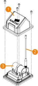
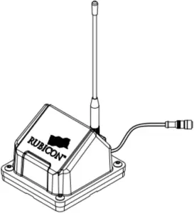
Figure 1 - FerIT Node components
- Cover
- Antenna
- Battery
Dimensions
Note:
Dimensions are given in millimetres and [inches].
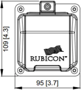
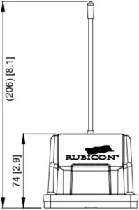
Figure 2 - FerIT Node top view Figure 3 - FerIT Node front view
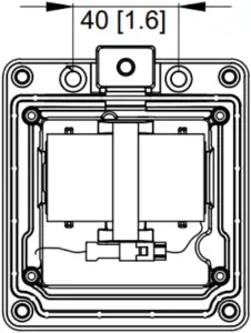
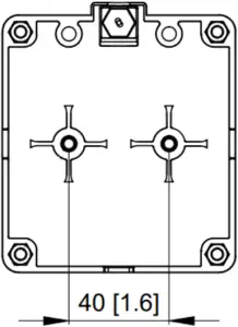
Figure 4 - FerIT Node rear mounting Figure 5 - FerIT Node base mounting
Elecrical Wiring

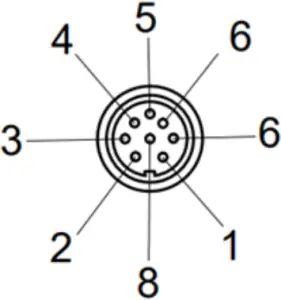
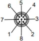
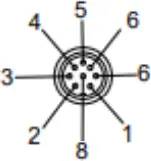
Figure 6 - FerIT Node Pinouts
| Node | Sensor | Type |
| Pin 1 | 1 | SDI12 |
| Pin 2 | 2 | 12C-SCL |
| Pin 3 | 3 | 12C-SCA |
| Pin 4 | 4 | RS485B |
| Pin 5 | 5 | Vin / Vout +VE |
| Pin 6 | 6 | RS485A |
| Pin 7 | 7 | Digital In/Out, 4-20 mA, analog voltage in |
| Pin 8 | 8 | Vin / Vout -VE |
Table 1 - FerIT Node Pinouts
FerIT Solar Node
Components
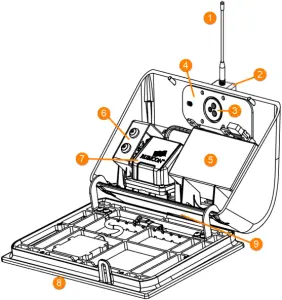
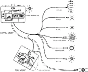
Figure 7 - FerIT Solar Node components
- Antenna
- Antenna mounting
- Loom connector (rear mounting)
- Rear mounting location
- Battery
- Power module
- Integrated FerIT Node
- Solar panel
- Base mounting and loom connector location
Dimensions
Note:
Dimensions are given in millimetres and [inches].
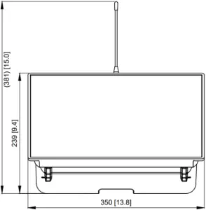
Figure 8 - FerIT Solar Node front view
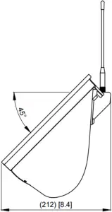
Figure 9 - FerIT Solar Node side view
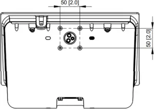
Figure 10 - FerIT Solar Node rear mounting
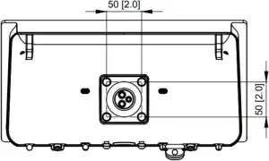
Figure 11 - FerIT Solar Node base mounting
Electrical Wiring
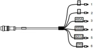
Power Connector
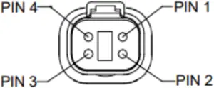
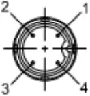
Figure 12 - FerIT Solar Node power connector pinouts
| Node | Type |
| Pin 1 | Vout +VE |
| Pin 2 | Vout –VE |
| Pin 3 | RS485B |
| Pin 4 | RS485A |
Table 2 - FerIT Solar Node Pinouts
Safety Precautions
Please make safety a priority when you are carrying out any work at a site. We recommend that you perform a site-specific risk assessment to identify any potential risks before commencing any work at a site.
Hazards
This topic lists identified hazards and options for dealing with them. Hazards that are specific to particular activities are also listed in the relevant topics.
Note:
If any of these hazards are present, refer to the relevant Occupational Health and Safety regulations for the region for guidance.
If there is a conflict between the instructions in this manual and an applicable national or local safety code, the national or local code must take precedence.
Identified hazards for working with the Weather Station are:
Environmental hazards
Hazards that apply to working outdoors.
 Hazard Extreme weather
- Be aware of expected weather conditions and wear suitable clothing
- In hot weather, take sunscreen and adequate drinking water. Watch your companions for signs of dehydration.
- In cold weather, wear warm clothing and carry chains for vehicles
 Hazard: Traffic
- Take care when exiting your vehicle and when working near traffic.
- If necessary, erect warning signs or bollards.
- Ensure that your vehicle is not a hazard to other vehicles.
 Hazard: Power lines
Follow appropriate safety regulations when working near power lines
 Hazard: Fire
Observe local fire restrictions.
Site hazards
Hazards that apply to working in remote or rural areas and around water.
 Hazard: Heights
- Follow approved safety procedures when working with ladders or elevated platforms.
- Use a platform ladder if the FerIT is being installed at a height above 2 meters.
 Hazard: Slipping
- Wear slip-resistant footwear
- Keep access-ways clear
 Hazard: Dangerous animals and livestock
- If there is livestock in the area, barricade off the work area or have livestock moved
- Watch out for snakes and biting insects when lifting equipment or removing covers
- Carry a first aid kit and an EpiPen
Work hazards
Hazards that apply to working with machinery, power tools, or heavy equipment.
 Hazard: Sharp objects
Wear protective clothing, boots and gloves when handling sharp objects and objects with rough surfaces, burrs and sharp edges
 Hazard: Falling objects
- Wear protective clothing, helmets, boots and gloves.
- Ensure that the FerIT is securely fixed to the mast.
Safety Equipment
The following safety equipment may be required during the installation of Rubicon products.
 Steel capped boots
  Dust mask or respirator
 Gloves
  Face protection
 Safety glasses
  Noise protection
 Hi-visibility vest
  Flotation device
 Helmet
  Safety harness
 Residual current device
  First Aid kit
Installation
Installation Options
The FerIT Node and the FerIT Solar Node are mounted on a pole using a suitable mounting bracket. You can mount the FerIT to an existing pole, or use the optional star picket or ground screw mounting options. The FerIT should be mounted at least 1.5m off the ground, and above nearby crops or objects where possible.
FerIT Node Installation
The FerIT Node can be connected to a mounting bracket using one of the following options depending on the bracket design:
- Two M5 bolts on the base of the FerIT Node. This is the most common mounting option.
- Two button head bolts on either side of the antenna. Remove the FerIT Node cover to access these mounting screws.
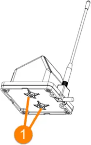
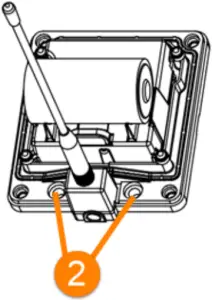
Figure 13 - FerIT Node mounting locations (1) Base, (2) Rear
Appendix: FerIT Wiring20 14
FerIT Solar Node Installation
 Battery handling:
Please take care when handling the FerIT Solar Node internal battery. This may be a fire hazard if it is dropped onto a hard surface.
The FerIT Solar Node can be connected to a mounting bracket using one of the following options depending on the bracket design:
- Four M6 bolts on the base of the FerIT Solar Node. Two screw into captive nuts and two must be secured with M6 Nyloc nuts.
- Four M6 bolts on the rear of the FerIT Solar Node.
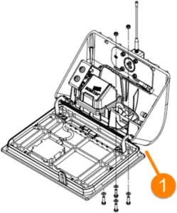
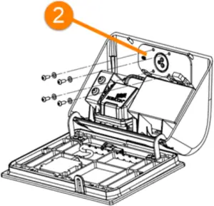
Figure 15 - FerIT Solar Node mounting locations - (1) Base, (2) Rear
Solar panel orientation
The FerIT Solar Node includes an integrated solar panel. This must face north in the southern hemisphere and south in the northern hemisphere.
Certification
FerIT Regulatory Requirements
This equipment has been tested and found to comply with the limits for a Class B digital device, pursuant to Part 15 of the FCC Rules. These limits are designed to provide reasonable protection against harmful interference in a residential installation. This equipment generates, uses and can radiate radio frequency energy and, if not installed and used in accordance with the instructions, may cause harmful interference to radio communications. However, there is no guarantee that interference will not occur in a particular installation. If this equipment does cause harmful interference to radio or television reception, which can be determined by turning the equipment off and on, the user is encourage to try to correct the interference by one or more of the following measures:
- Reorient or relocate the receiving antenna
- Increase the separation between the equipment and receiver
- Connect the equipment into an outlet on a circuit different from that to which the receiver is connected
- Consult the dealer or an experienced radio/TV technician for help
WARNING: 900MHz Operation:
To satisfy FCC RF exposure requirements for mobile transmitting devices, a separation distance of 21 cm or more should be maintained between the antenna of this device and persons during device operation. To ensure compliance, operations at closer than this distance is not recommended. The antenna used for this transmitter must not be co-located in conjunction with any other antenna or transmitter.
Approved Antenna Options
P400 Models (81338, 81343)
| Type | Rubicon Part Number | Description |
| Omni Directional | 81182 | 3dBi, 900MHz Whip Antenna Reverse SMA |
| Omni Directional | 81842 | 6dBi, 900MHz Omni Directional N-TYPE |
LoRa Models (81170, 81342)
| Type | Rubicon Part Number | Description |
| Omni Directional | 81182 | 3dBi, 900MHz Whip Antenna Reverse SMA |
This device complies with Part 15 of the FCC Rules. Operation is subject to the following two conditions:
- This device may not cause interference; and
- This device must accept any interference, including interference that may cause undesired
operation of the device.
Warning:
Any changes or modifications not expressively approved by Rubicon Global Pty Ltd could void the user’s authority to operate this equipment.
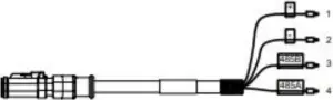
Appendix: FerIT Wiring
FERIT NODE
BOOTLACES
| NODE | SENSOR | TYPE |
| Pin 1 | 5 | SDI12 |
| Pin 2 | NC | |
| Pin 3 | NC | |
| Pin 4 | 4 | RS485B |
| Pin 5 | 1 | +VE |
| Pin 6 | 3 | RS485A |
| Pin 7 | 6 | Dig In/Out, 4-20mA, Analog Voltage in |
| Pin 8 | 2 | -VE |
![]()
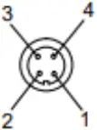
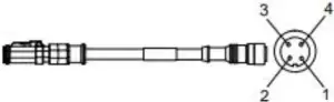
M12 4 PIN
| NODE | SENSOR | TYPE |
| Pin 1 | NC | |
| Pin 2 | NC | |
| Pin 3 | NC | |
| Pin 4 | 3 | RS485B |
| Pin 5 | 1 | +VE |
| Pin 6 | 4 | RS485A |
| Pin 7 | NC | |
| Pin 8 | 2 | -VE |
![]()

M8 4 PIN
| NODE | SENSOR | TYPE |
| Pin 1 | NC | |
| Pin 2 | NC | |
| Pin 3 | NC | |
| Pin 4 | 4 | RS485B |
| Pin 5 | 1 | +VE |
| Pin 6 | 3 | RS485A |
| Pin 7 | NC | |
| Pin 8 | 2 | -VE |
![]()
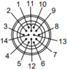
SENTEK PROBE (RS485)
| NODE | SENSOR | TYPE |
| Pin 1 | NC | |
| Pin 2 | NC | |
| Pin 3 | NC | |
| Pin 4 | 10 | RS485B |
| Pin 5 | 1 | +VE |
| Pin 6 | 13 | RS485A |
| Pin 7 | NC | |
| Pin 8 | 2 | -VE |
![]()
AQUASPY (RS485)
| NODE | SENSOR | TYPE |
| Pin 1 | NC | |
| Pin 2 | NC | |
| Pin 3 | NC | |
| Pin 4 | 3 | RS485B |
| Pin 5 | 1 | +VE |
| Pin 6 | 2 | RS485A |
| Pin 7 | NC | |
| Pin 8 | 4 | -VE |
![]()
M12 8 PIN
| NODE | SENSOR | TYPE |
| Pin 1 | 1 | SDI12 |
| Pin 2 | 2 | 12C-SCL |
| Pin 3 | 3 | 12C-SCA |
| Pin 4 | 4 | RS485B |
| Pin 5 | 5 | +VE |
| Pin 6 | 6 | RS485A |
| Pin 7 | 7 | Dig In/Out, 4-20mA, Analog Voltage in |
| Pin 8 | 8 | -VE |
FERIT SOLAR NODE
BOOTLACES
| NODE | SENSOR | TYPE |
| Pin 1 | 5 | SDI12 |
| Pin 2 | NC | |
| Pin 3 | NC | |
| Pin 4 | 4 | RS485B |
| Pin 5 | 1 | +VE |
| Pin 6 | 3 | RS485A |
| Pin 7 | 6 | Dig In/Out, 4-20mA, Analog Voltage in |
| Pin 8 | 2 | -VE |
M12 4 PIN
| NODE | SENSOR | TYPE |
| Pin 1 | NC | SDI12 |
| Pin 2 | NC | |
| Pin 3 | NC | |
| Pin 4 | 3 | RS485B |
| Pin 5 | 1 | +VE |
| Pin 6 | 4 | RS485A |
| Pin 7 | NC | Dig In/Out |
| Pin 8 | 2 | -VE |
M8 4 PIN
| NODE | SENSOR | TYPE |
| Pin 1 | NC | |
| Pin 2 | NC | |
| Pin 3 | NC | |
| Pin 4 | 4 | RS485B |
| Pin 5 | 1 | +VE |
| Pin 6 | 3 | RS485A |
| Pin 7 | NC | |
| Pin 8 | 2 | -VE |
SENTEK PROBE (RS485)
| NODE | SENSOR | TYPE |
| Pin 1 | NC | |
| Pin 2 | NC | |
| Pin 3 | NC | |
| Pin 4 | 10 | RS485B |
| Pin 5 | 1 | +VE |
| Pin 6 | 13 | RS485A |
| Pin 7 | NC | |
| Pin 8 | 2 | -VE |
AQUASPY (RS485)
| NODE | SENSOR | TYPE |
| Pin 1 | NC | |
| Pin 2 | NC | |
| Pin 3 | NC | |
| Pin 4 | 3 | RS485B |
| Pin 5 | 1 | +VE |
| Pin 6 | 2 | RS485A |
| Pin 7 | NC | |
| Pin 8 | 4 | -VE |
M12 8 PIN
| NODE | SENSOR | TYPE |
| Pin 1 | 1 | SDI12 |
| Pin 2 | 2 | 12C-SCL |
| Pin 3 | 3 | 12C-SCA |
| Pin 4 | 4 | RS485B |
| Pin 5 | 5 | +VE |
| Pin 6 | 6 | RS485A |
| Pin 7 | 7 | Dig In/Out, 4-20mA, Analog Voltage in |
| Pin 8 | 8 | -VE |
| SOLAR NODE | Device | TYPE |
| Pin 1 | 1 | +VE |
| Pin 2 | 2 | -VE |
| Pin 3 | 3 | RS485B |
| Pin 4 | 4 | RS485A |
| SOLAR NODE | Device | TYPE |
| Pin 1 | 1 | +VE |
| Pin 2 | 2 | -VE |
| Pin 3 | 3 | RS485B |
| Pin 4 | 4 | RS485A |
![]()
Version: 1.0 , 27/08/2020


