![]() 32326295
32326295
Issue D
Installation Instructions for the
AMR 4-Pin Quadrature Sensor Integrated Circuit:
VM821Q1
GENERAL INFORMATION
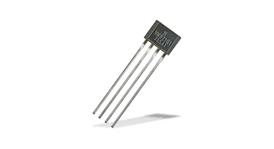
Honeywell’s Anisotropic Magnetoresistive (AMR) 4-Pin Quadrature Sensor Integrated Circuit (IC) is designed to detect the speed and direction and position of a ring magnet encoder target using a unique* bridge design. The frequency of the output is proportional to the rotational speed of the target, and the rotational direction is encoded by the phase between the outputs. The sensor IC works over a wide range of speeds, temperatures, and air gaps. *Patent Pending
CAUTION
ELECTROSTATIC DISCHARGE DAMAGE
Ensure proper ESD precautions are followed when handling this product.
Failure to comply with these instructions may result in product damage.
SOLDERING AND ASSEMBLY
CAUTION
IMPROPER SOLDERING
- Ensure leads are adequately supported during any forming/shearing operation so that they are not stressed inside the plastic case.
- Limit exposure to high temperatures.
Failure to comply with these instructions may result in product damage
Wave solder at 250°C to 260°C [482°F to 500°F] for a maximum of three seconds. Burrs are allowed only if the full lead length will pass through a 0,68 mm [0.027 in] dia. hole.
CLEANING
CAUTION
IMPROPER CLEANING
Do not use a pressure washer. A high-pressure stream could force contaminants into the package.
Failure to comply with these instructions may result in product damage.
Table 1. Operating Characteristics (At 4.0 V ≤ V ≤ 24 V, -40°C ≤ T ≤ 150°C, unless otherwise specified.)
| Characteristic | Symbol | Condition | Min. | 1YP. | Max. | Unit |
| Supply voltage | Vs | — | 4.0 | — | 24 | V |
| Supply current | Icc | — | — | — | 20 | mA |
| Output low | Vsat | Vs – 5 V. Iol – 5 mA | — | — | 400 | mV |
| Output leakage | Ioh | Voh – 24 V | — | — | 10 | μA |
| Output current | Iol | — | — | — | 20 | mA |
| Duty cycle | — | 2 mm pole width | 40 | 50 | 60 | % |
| Phase | — | 2 mm pole width | 70 | 90 | 110 | o |
| Output switching time: rise time fall time | tr tf | Vs – 5 V, RL – 1 kOhm to 5 V, Cl- 20 pF Vs – 5 V, RL- 1 kOhm to 5 V, Cl.- 20 pF | — — | — — | 1.5 1.5 | μs |
| Switching frequency | f | — | — | 35 | — | kHz |
Table 2. Output Configuration
| Characteristic | Condition | Configuration |
| Number of pulses per pole | — | 1 |
| Phase polarity | rotation from pin 4 to pin 1 as shown in Figure 4. | output A leads B |
Advanced Sensing Technologies
Table 3. Application Requirements (At 4.0 V ≤ VS ≤ 24 V, -40°C ≤ TA ≤ 150°C.)
| Characteristic | Symbol | Condition | Min. | Typ. | Max. | Unit |
| Magnetic flux | B | Dmax, max. an air gap, max. temp | ±30 | — | — | Gauss |
| Magnetic flux with valid direction indication, increased jitter | B | Dmax, max. an air gap, max. temp | ±10 | – | – | Gauss |
| Metering resistor | R | — | SO | 160 | — | Ohm |
Table 4. Absolute Maximum Ratings
| Characteristic | Symbol | Condition | Min. | Typ. | Max. | Unit |
| Operating temperature | Ts | — | -40 [-40] | — | 150 [302] | °C [°F] |
| Junction temperature | 11, | — | -40 [-40] | — | 165 [329] | °C [°F] |
| Storage temperature | Ts | — | -40 [-40] | — | 150 [302] | °C [°F] |
| Thermal resistance | Robs, | — | — | — | — | °C/W |
| Supply voltage | Vs | — | -27. | — | 27. | V |
| Soldering temperature | — | 3 s max. | — | — | 260 [500] | °C [°F] |
| ESD (HBM) | VESO | JEDEC JS-002-2014 | — | — | ±6 | kV |
| Output short circuit | — | with no current limiting resistor | — | — | 24 | V |
NOTICE
Absolute maximum ratings are the extreme limits the device will momentarily withstand without damage to the device. Electrical and mechanical characteristics are not guaranteed if the rated voltage and/or currents are exceeded, nor will the device necessarily operates at absolute maximum ratings.
NOTICE
Large, stray magnetic fields in the vicinity of the sensor may adversely affect sensor performance.
Figure 1. Block Diagram
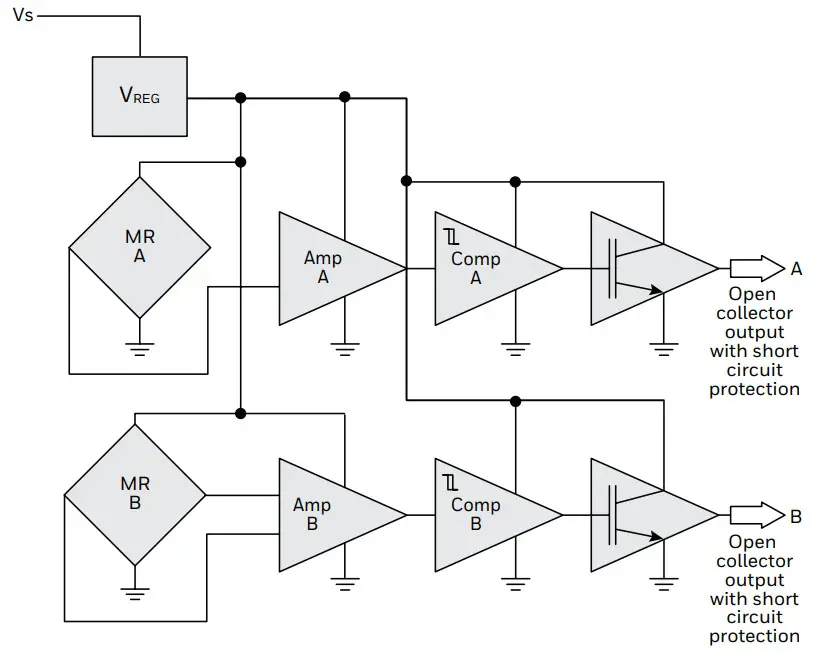
Figure 2. Basic Application Circuit
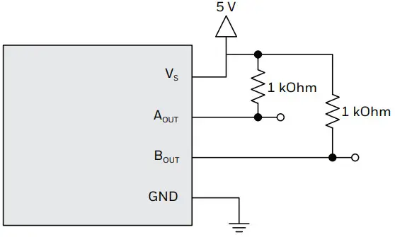
Figure 3. Transfer Characteristics
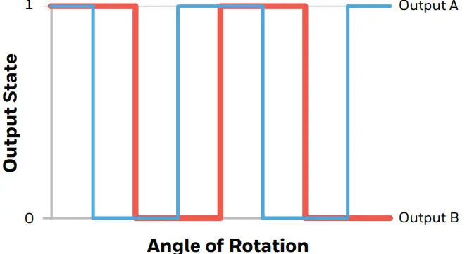
Phase Calculation Definition
This method isolates the phase from the duty cycle. It also best correlates to the analysis of the fundamental frequency in the frequency domain.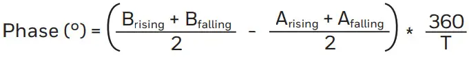
Where:
Arising = rising edge of output A
Afalling = falling edge of output A
Brising = nearest falling edge of output B to Arising
Bfalling = next falling edge of output B
T = period of one cycle
Figure 4. Sensor IC Mounting Orientation
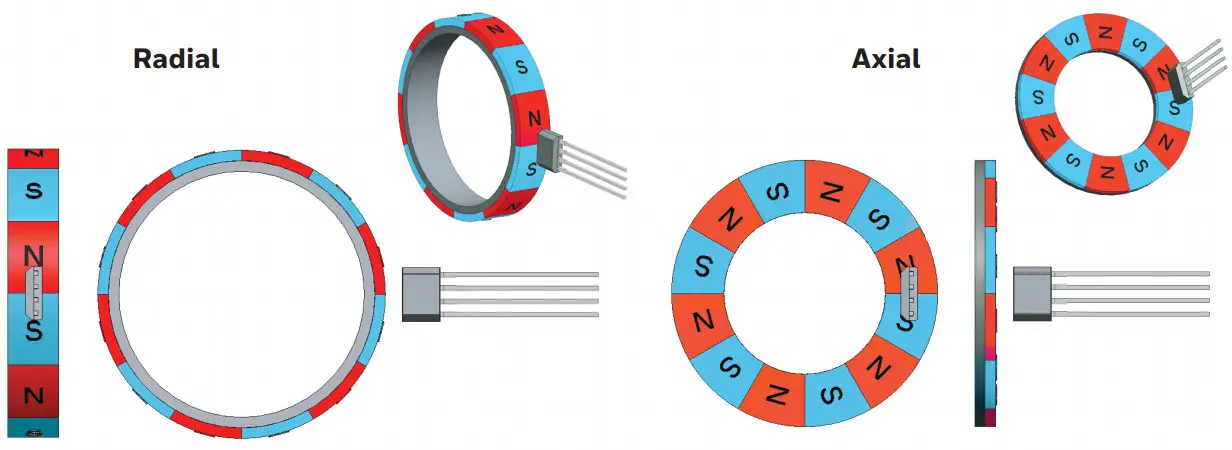
Figure 5. Dimensions and Product Marking (For reference only mm/[in])
![Honeywell VM821Q1 AMR 4-Pin Quadrature Sensor -Figure 5. Dimensions and Product Marking (For reference only mm[in])](https://static-data1.manualsee.com/1/img/156/533592/2021/09/Honeywell-VM821Q1-AMR-4-Pin-Quadrature-Sensor-Figure-5.-Dimensions-and-Product-Marking-For-reference-only-mmin.jpg) | ![Honeywell VM821Q1 AMR 4-Pin Quadrature Sensor -Figure 5. Dimensions and Product Marking (For reference only mm2[in])](https://static-data1.manualsee.com/1/img/156/533592/2021/09/Honeywell-VM821Q1-AMR-4-Pin-Quadrature-Sensor-Figure-5.-Dimensions-and-Product-Marking-For-reference-only-mm2in.jpg) |
Pinout
| Pin Number | Symbol | Function |
| 1 | Vs | supply voltage |
| 2 | A | output |
| 3 | B | output |
| 4 | GND | ground |
 WARNING
PERSONAL INJURY
DO NOT USE these products as safety or emergency stop devices or in any other application where the failure of the product could result in personal injury.
Failure to comply with these instructions could result in death or serious injury.
Warranty/Remedy
Honeywell warrants goods of its manufacture as being free of defective materials and faulty workmanship during the applicable warranty period. Honeywell’s standard product warranty applies unless agreed to otherwise by Honeywell in writing; please refer to your order acknowledgment or consult your local sales office for specific warranty details. If warranted goods are returned to Honeywell during the period of coverage, Honeywell will repair or replace, at its option, without charge those items that Honeywell, in its sole discretion, finds defective.
The foregoing is the buyer’s sole remedy and is in lieu of all other warranties, expressed or implied, including those of merchantability and fitness for a particular purpose. In no event shall Honeywell be liable for consequential, special, or indirect damages.
While Honeywell may provide application assistance personally, through our literature and the Honeywell website, it is the buyer’s sole responsibility to determine the suitability of the product in the application.
Specifications may change without notice. The information we supply is believed to be accurate and reliable as of this writing. However, Honeywell assumes no responsibility for its use.
For more information
Honeywell Sensing and Internet of Things services its customers through a worldwide network of sales offices and distributors. For application assistance, current specifications, pricing, or the nearest Authorized Distributor, visit sensing.honeywell.com or call:
Asia Pacific +65 6355-2828
Europe +44 (0) 1698 481481
USA/Canada +1-800-537-6945
Honeywell Advanced Sensing Technologies
830 East Arapaho Road
Richardson, TX 75081
sps.honeywell.com/ast
![]() 32326295-D-EN | D | 05/21
32326295-D-EN | D | 05/21
© 2021 Honeywell International Inc.


