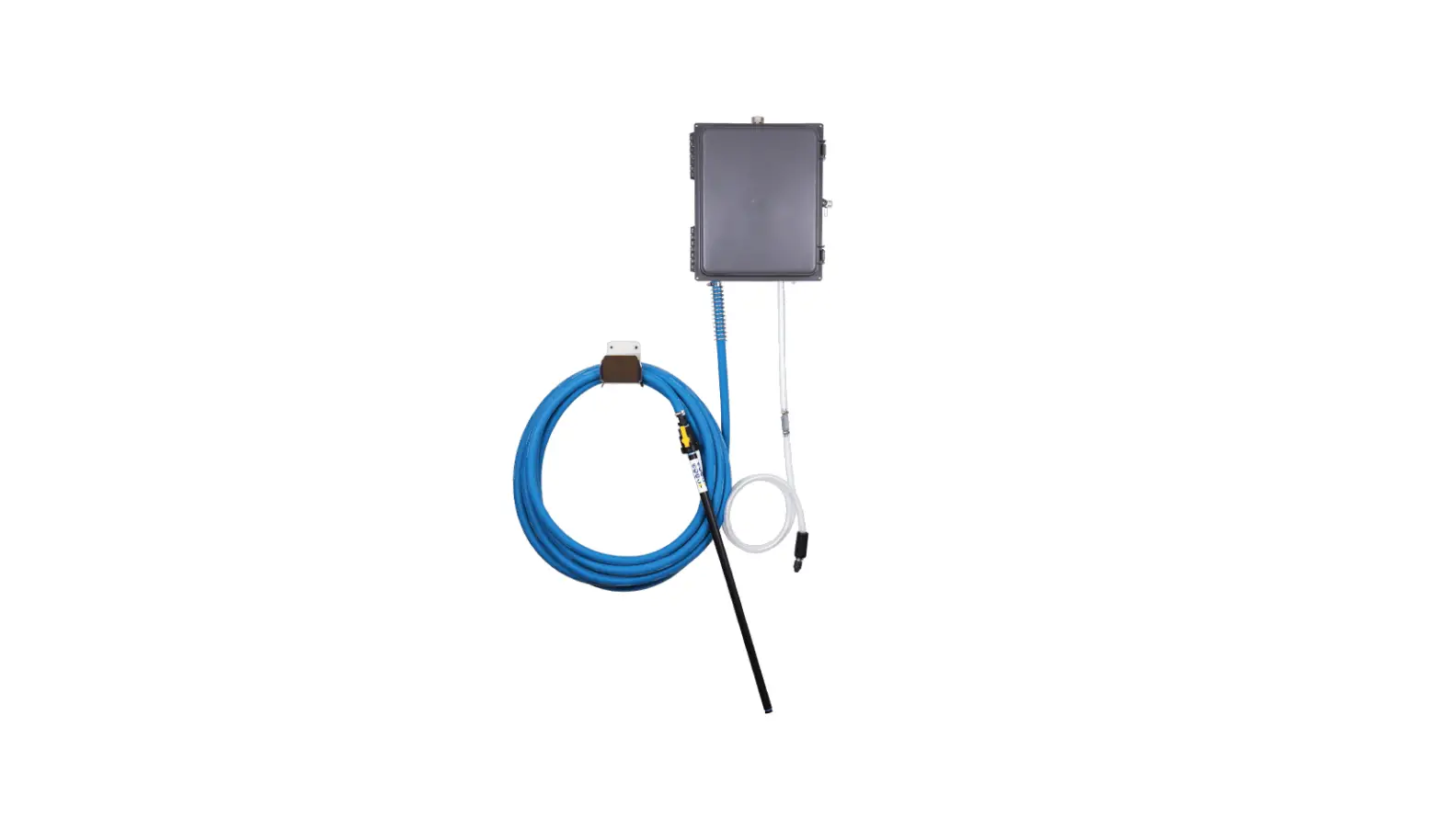
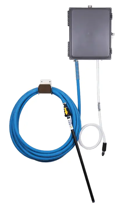
FOAMit FI-WC-11AP High Concentration Foam Unit with All-Poly Fittings
WARNING
Read this manual completely and understand the machine before operating or servicing it.
- Read all instructions before installing or operating unit.
- Always wear appropriate personal protective equipment (PPE) when operating or servicing unit.
- Always follow all chemical safety precautions and handling instructions provided by the chemical manufacturer and Safety Data Sheet (SDS).
- If this unit is modified or serviced with parts not listed in this manual, the unit may not operate correctly.
- Never point the discharge wand at yourself, another person, or any object you do not want covered in chemical.
- Always depressurize unit after use (as described in the After Use Instructions). Always store unit depressurized, with the discharge valve in the closed position.
- Do not exceed an incoming air pressure of 100 psi (7 bar).
- Do not exceed a fluid temperature of 100˚F (37˚C).
- Always flush the unit with fresh water for 2-4 minutes when switching from an alkaline to an acid or an acid to an alkaline.
- Only use clean and dry air. Air must be filtered and free of moisture or pump life will be diminished. If needed, install an air dryer before unit.
- Do not use an air lubricator before the unit.
- Never use unit with hydrocarbons or flammable products.
PROTECT THE ENVIRONMENT
Please dispose of packaging materials, old machine components, and hazardous fluids in an environmentally safe way according to local waste disposal regulations.
| OPTIONS: (unit with 1-product pick up) | |
| Pump Seal Material | |
| FI-WC-11AP | Santoprene (standard) |
| Viton (V) | |
| Kalrez (K) | |
| Add bold option codes to item number as shown. For standard options, no option code is needed. Examples: • FI-WC-11AP (standard unit with Santoprene pump seals) • FI-WC-11APV (unit with Viton pump seals) | |
| OPTIONS: (unit with 2-products pick up) | ||
| Pump Seal Material | ||
| FI-WC-11AP | Santoprene (standard) | 2 |
| Viton (V) | ||
| Kalrez (K) | ||
| Add bold option codes to item number as shown. For standard options, no option code is needed. Examples: • FI-WC-11AP2 (standard unit with Santoprene pump seals) • FI-WC-11APK2 (unit with Kalrez pump seals) | ||
| REQUIREMENTS | |
| Compressed air requirements | 40-80 psi (2.8-5.5 bar) with 5-10 cfm (141.6-283.2 l/min) |
| Water requirements | 10-100 psi (0.7 – 6.9 bar) Backflow prevention is required – consult local plumbing ordinances for more information. |
| Liquid temperature range | 40-100˚F (4.4-37.8˚C) |
| Chemical compatibility | Chemical products used with this equipment must be formulated for this type of application and compatible with unit materials and pump seals. For more information on chemical compatibility, consult the manufacturer or MSDS for your product or contact our customer service department. |
| SPECIFICATIONS | ||
| FI-WC-11AP | FI-WC-11AP2 | |
| Power type | Compressed air | |
| Chemical pickup type | Draws from concentrated product | |
| Dilution ratio range (water:chemical)* | 1:1 to 16:1 | |
| Number of products unit can draw from | One product | Two products, one at a time |
| Suction line length/diameter | 8 ft. (2.4 m) clearbraid hose with 1/2 in. (12.7 mm) inside diameter (for each product) | |
| Discharge hose diameter/length | 50 ft. (15.2 m) hose, with 3/4 in. (19 mm) inside diameter | |
| Discharge wand/tip type | 32 in. (81.3 cm) polypropylene wand with zero tip and polypropylene ball valve | |
| Output distance | 15-20 ft. (4.6-6.1 m) | |
| Output volume | 20 gal/min (75.7 l/min) of foam | |
| Flow rate* | 1.6 gal/min (6.1 l/min) | |
| Pump seals | Santoprene, Viton, or Kalrez | |
| Fluid fittings type | All-poly | |
Installation Instructions
- Remove all components from packaging.
- Select desired area to mount the control box.
Note: We recommend mounting the control box at a height of 6 feet or less. The chemical suction lines must reach the bottom of the chemical container. The bottom of the chemical container should not be positioned higher than the bottom of the control box. - Attach the control box mounting feet to the back of the control box, using the four screws provided in the parts package.
- Mount the control box to the wall using four of the screws and plastic anchors provided in the parts package. Note: To drill holes for the plastic anchors, use a 5/16 inch drill bit.
- Mount the hose hanger in a convenient location using the remaining two screws and anchors provided in the parts package.
- Attach the discharge hose assembly to the discharge hose barb (HB1234) and secure it with the larger hose clamp provided in the parts package.
- Connect the air inlet hose barb (HBSS1438) provided in the parts package to the air inlet valve (BVB14) located on the side of the control box. Then attach a 3/8 inch I.D. air line from your air compressor to the air inlet hose barb, and secure it with the smaller hose clamp provided in the parts package.
- Connect a water line to the water inlet fitting (SNB34GH). Note: A back-flow preventer must be installed in the water line – check local plumbing codes to ensure proper installation.
- Insert the proper metering tips and connect the chemical intake lines to the inlet barbs. Note: Use the included metering tip color charts to determine the appropriate metering tip based on the product and dilution rate you will be using.
- Place the other end of each chemical intake line into a chemical container.
| METERING TIP COLOR CHART | ||
| Metering Tip Color | Diameter (Inches) | Ratios (Water:Chemical)** |
| NO TIP | NO TIP | 1:1 |
| GREY | 0.128 | 1.5:1 |
| BLACK | 0.098 | 2.25:1 |
| BEIGE | 0.07 | 3.25:1 |
| RED | 0.052 | 4.25:1 |
| WHITE | 0.043 | 6.5:1 |
| BLUE | 0.04 | 7.5:1 |
| TAN | 0.035 | 9:1 |
| GREEN | 0.028 | 11:1 |
| ORANGE | 0.025 | 16:1 |
| BROWN* | 0.023 | 22:1 |
| YELLOW* | 0.02 | 27:1 |
| PURPLE* | 0.014 | 43:1 |
| PINK* | 0.01 | 53:1 |
| * Use of these metering tips is not recommended. At ratios greater than 16:1 (water:chemical), the output volume of the unit may be greatly reduced. ** Injection rates will vary based on chemical viscosity, air pressure, and many other factors. We recommend testing unit output to verify injection rate prior to use. | ||
Operation Instructions
- Slowly open the discharge valve (HV34) to begin foaming. The discharge valve should be completely open while foaming.
- Adjust the needle valve (NV14Y), located inside the control box, to regulate the wetness or dryness of the foam following the steps below:
- a. Close needle valve (NV14Y) completely in clockwise direction.
- b. Open needle valve (NV14Y) in counter-clockwise direction 3 complete turns.
- c. Continue to open needle valve in ¼ turn increments, allowing 30 seconds between adjustments, until desired consistency of foam is achieved.
After Use Instructions:
- Place the chemical suction line into a container of water.
- Open the discharge valve (HV34), and allow the unit to be flushed with water for approximately 2-4 minutes or until all chemical has been discharged from system.
- Close air inlet valve (BVB14).
- Shut off the water supply to the unit.
- Open the discharge valve to relieve any pressure remaining in the unit.
- Close the discharge valve after all pressure has been relieved from the unit. Store the unit with the discharge valve in the closed position.
Maintenance Instructions
To keep your foam unit operating properly, periodically perform the following maintenance procedures:
Note: Before performing any maintenance, ensure that the unit has been disconnected from the air/water supply and depressurized according to the “After Use Instructions” above.
- Inspect the pump (P56/P56K/P56V) for wear and leaks.
- Inspect all hoses for leaks or excessive wear. Make sure all hose clamps are in good condition and properly secured.
- Replace the filter located within the air regulator (R25) as needed. Clean by unthreading the air regulator bowl from the air regulator (R25).
- Check the chemical metering tips, intake lines and strainers for debris and clean as needed.
- Drain the air compressor tank on a regular basis to help extend pump life. An air source with a high moisture content will accelerate pump wear.
Note: If the air source has a high moisture content, you may wish to install a water separator (WS-20CFM) before the unit.
Troubleshooting Instructions
- Check to ensure that the discharge hose is uncoiled properly, and that there are no kinks that could obstruct fluid flow.
- Check the air regulator bowl and air filter for debris such as water, oil, or rust particles. Clean by unthreading the air regulator bowl from the air regulator (R25).
- If air passes through the pump (P56/P56K/P56V) without cycling, the pump needs to be replaced.
- If solution backs up into the air regulator bowl, the check valve (CV38-AP) needs to be replaced.
- Check for proper air pressure on the air gauge (AG100). The air regulator (R25) is factory set at 50 psi (3.4 bar). Operating range is 40 to 80 psi (3 to 5 bar) with 5 to 10 CFM (141.6 to 283.3 l/min).
- If the unit operates at a reduced pressure:
- Check the air compressor supplying the unit. If the pressure is less than 40 psi (3 bar), turn the unit off until the compressor can catch up.
- If the air supply is 50 psi (3.4 bar) or above, check the air gauge (AG100), which should read near 50 psi (3.4 bar). If the air gauge reads more or less than 50 psi (3.4 bar), adjust the pressure by turning the knob on the top of the air regulator (R25).
- Check the chemical metering tips, intake lines and strainers for debris or damage. Clean or replace as needed. To prevent damage to the unit, strainers must always be used.
- Make sure proper foaming chemical and concentration are being used.
- If the needle valve (NV14Y) is open too far, the pump
(P56/P56K/P56V) may cycle improperly due to lack of air pressure. If this occurs, close and readjust the needle valve (NV14Y) as described in Operation Instruction. - If foam comes out wet, no matter where the needle valve (NV14Y) is positioned, the check valve (CV38-AP) may need to be replaced.
- Check for proper water pressure on the water pressure gauge (WRG14). To check the pressure:
- With the unit running, open the discharge valve
(HV60/HV34) and allow the unit to run for about 1 minute. - Close the discharge valve (HV60/HV34).
- Check the water pressure gauge (WRG14). The pressure should read 30 psi (2.1 bar).
- If necessary, adjust the water regulator using the flathead screw on the regulator body. The water pressure should be set at 30 psi (2.1 bar). Setting the pressure higher or lower may damage the unit or cause it to malfunction.
- With the unit running, open the discharge valve
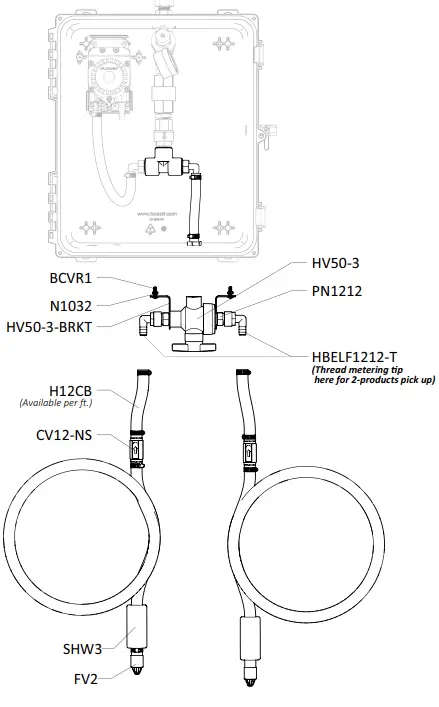
PARTS DIAGRAMS – UNITS WITH STANDARD FITTINGS
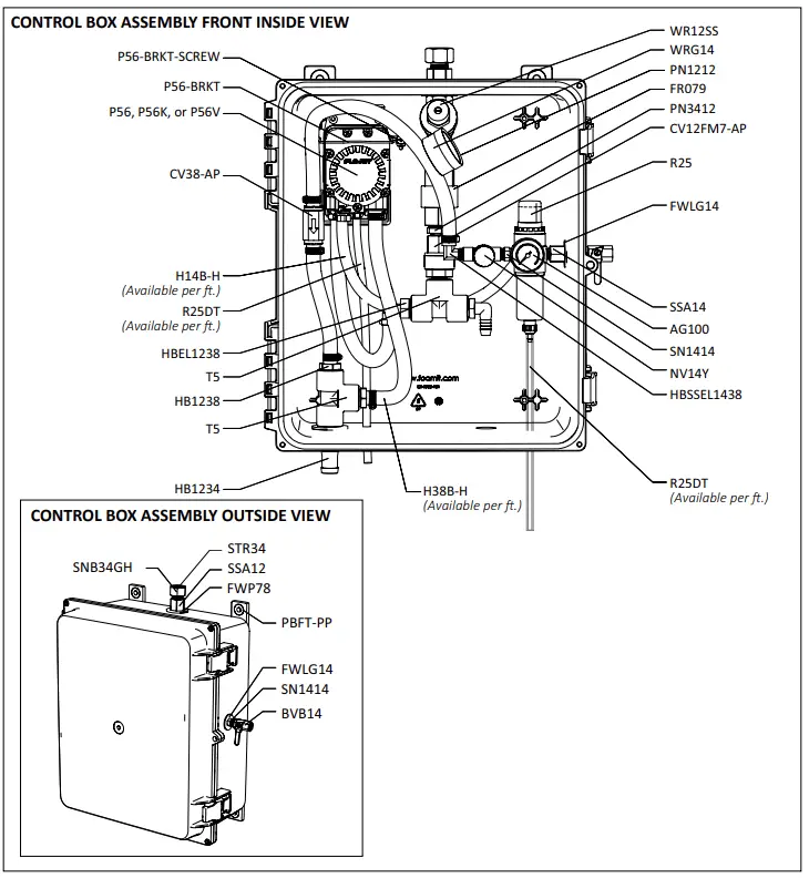
PARTS DIAGRAMS
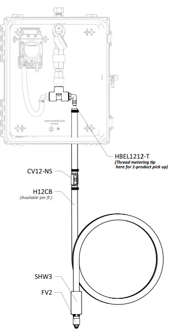
- PRODUCT PICK UP LINE

- PRODUCT PICK UP LINE

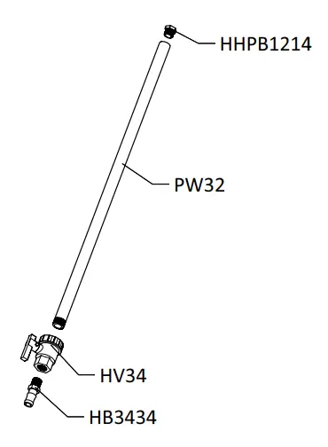
ZERO TIP FOAM WAND ASSEMBLY ITEM NUMBER: PWA32
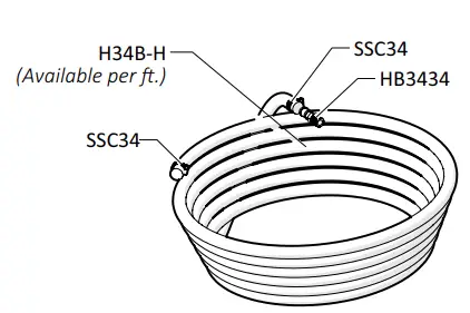
50 ft (15 m) HOSE ASSEMBLY ITEM NUMBER: H34-50-AP
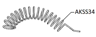
ANTI-KINK SPRING ASSEMBLY ITEM NUMBER: AKSS34
OPTIONAL COMPONENT
WATER SEPARATOR ITEM NUMBER: WS-20CFM
LEGACY WATER REGULATOR ASSEMBLY
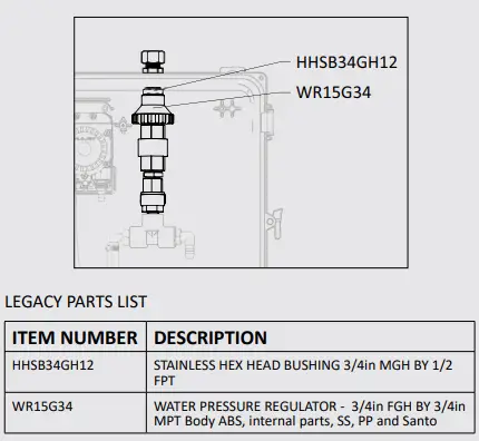
| ITEM NUMBER | DESCRIPTION |
| AG100 | 1.5 INCH DRY MODEL 20 DUAL SCALE GAUGE |
| AKSS34-P | SS ANTI-KINK SPRING FOR 3/4 INCH HOSE |
| AKSS-HPC | ANTI-KINK STAINLESS STEEL HITCH PIN CLIP |
| BCVR1 | 10-32 X 1/2 PHIL PAN HEAD SS |
| BVB14 | AIR INLET VALVE – VA BRS 025-4F4F-BT, NICKEL |
| CV12FM7-AP | WHITE ½ INCH FEMALE NPT INLET – BLACK ½ INCH MALE NPT OUTLET – EP SLEAS 7 PSI HASTELLOY SPRING |
| CV12-NS | 1/2in BARB X 1/2in BARB PVC CHECK VALVE – NO SPRING – TEFLON BALL |
| CV38-AP | WHITE PVC CHECK VALVE 3/8 BARBS – HASTELLOY SPRING – TEFLON BALL |
| EC14-2 | OETIKER CLAMP 13.8 |
| FR079 | 687 SERIES FLOW RESTRICTOR – 0.79 GPM — FP FR 687-12F12F-E.79 GPM |
| FV2 | FOOT VALVE, VITON, BLUE |
| FWLG14 | .569 ID X 1.28 OD X .08 THICK FLAT WASHER SS 18-8 |
| FWP12 | 7/8 ID X 1.5 OD X 0.05 THK SSFW |
| FWP78 | 7/8in BY .137 BY 1 1/4in FLATWASHER 18-8 PLN |
| H12CB | 1/2 IN (ID) CLEARBRAID RF SERIES |
| H14B-H | 1/4 INCH BLUE HOSE- GOODYEAR HORIZON – Available per ft. |
| H34B-H | 3/4 INCH BLUE GOODYEAR HORIZON HOSE – Available per ft. |
| H38B-H | 3/8 INCH BLUE GOODYEAR HORIZON HOSE – Available per ft. |
| HB1234 | 1/2in MPT X 3/4in HOSE BARB |
| HB1238 | 1/2in MPT X 3/8in HOSE BARB |
| HB3434 | POLY HOSE BARB 3/4in X 3/4in |
| HBEL1212-T | HOSE BARB ELBOW 1/2in MPT X 1/2in BARB – TAPPED FOR METERING TIP |
| HBEL1238 | HOSE BARB ELBOW 1/2 X 3/8 |
| HBELF1212-T | HOSE BARB ELBOW 1/2in BY FPT 1/2in – TAPPED FOR METERING TIP |
| HBSS1438 | STAINLESS HOSE BARB 1/4 MPT X 3/8 BARB |
| HBSSEL1438 | STAINLESS HOSE BARB ELBOW 1/4 INCH NPT X 3/8 HOSE BARB |
| HBSSEL1814 | 304 STAINLESS ELBOW 1/8 INCH NPT X 1/4 INCH HOSE BARB |
| HHPB1214 | HEX HEAD POLY REDUCER BUSHING 1/2in X 1/4in |
| HHSB34GH12 | STAINLESS HEX HEAD BUSHING 3/4in MGH BY 1/2 FPT |
| HV34 | 3/4in POLY BALL VALVE |
| HV50-3 | 3-WAY BALL VALVE – 1/2 INCH – FIBER GLASS RE- ENFORCED POLYPROPELENE BODY – TEFLON SEATS – EPDM O-RING |
| HV50-3-BRKT | SS BRACKET FOR HV50-3 |
| MTK 511 | METERING TIP KIT – 511/530 |
| N1032 | 10-32 HEX MACH SCREW NUT 18-8 |
| NV14Y | FLOW CONTROL VALVE – INCLUDES BLACK KNOB |
| NV14Y-HNDL | KNOB FOR 2839-1/4 NEEDLE VALVE |
| P56 | 5700 PUMP WITH SANTOPRENE SEALS – INCLUDES HOSE BARBS, AIR FITTING, AND AIR PORT |
| P56K | 5700 PUMP WITH KALREZ SEALS – INCLUDES HOSE BARBS, AIR FITTING, AND AIR PORT |
| ITEM NUMBER | DESCRIPTION |
| P56V | 5700 PUMP WITH VITON SEALS – INCLUDES HOSE BARBS, AIR FITTING, AND AIR PORT |
| 20756103B | Polypro G57 Air Port x HB Straight, w/ Viton o-ring |
| HB14P | 1/4in BRASS HB AIR FITTING /G57/P56 |
| HB5638 | HOSE BARB FOR P56 PUMP |
| HB5638K | HOSE BARB FOR P56K PUMP |
| HB5638V | HOSE BARB FOR P56V PUMP |
| P56-BRKT | PUMP BRACKET- STAINLESS STEEL |
| P56-BRKT-SCREW | HI LO SCREW FOR RETAINING P56-BRKT |
| PB16138 | POLYPROPYLENE CONTROL BOX – WORKING DIMS 16x13x8 – PUMP MOUNT |
| PB16138-GSKT | NEOPRENE GASKET 0.220 INCH ROUND CORD STOCK – 61.125 INCHES |
| PB16138-LATCH | LATCH FOR PB16138 |
| PB16138-PIN | STAINLESS STEEL HINGE PIN FOR CONTROL BOX PB16138 – 1/8 x 4 3/4 x 1/2inches |
| PBFT-PP | MOUNTING FEET FOR POLYBOX – PB16138 – POLYPROPYLENE |
| PL16138 | CONTROL BOX LID – POLYPROPYLENE – 16x13x8 – HINGED LOCKABLE LID |
| PN1212 | 1/2in MPT X 1/2in MPT POLY NIPPLE |
| PN3412 | 3/4in MPT X 1/2in MPT POLY NIPPLE |
| PW32 | 3/4in BLACK POLY PRO X 32in – FPTOE & MPTOE – SCH.80 |
| R25 | AIR REGULATOR – 1/4fpt TWO PORT 1/8fpt TWO PORT – INCLUDES FILTER AND BOWL |
| AFR25 | AIR FILTER for R25 |
| ABR25 | METAL AIR BOWL for R25 |
| R25DT | 3/16 X 5/16 CLEAR PVC TUBING – Available per ft. |
| S1034FHL | 10 X 3/4 PHIL FLAT HI-LO THRD SCREW 18-8 |
| SA12B | GARDEN HOSE SWIVEL ADAPTER X 1/2 MPT |
| SHW3 | 3in LONG COATED WEIGHT |
| SN1414 | STAINLESS 1/4MPT X 1/4MPT NIPPLE |
| SNB34GH | BRASS 3/4 GH SWIVEL NUT |
| SSA12 | STAINLESS MALE/FEMALE S.S. ADAPTOR 1/2in X 1/2in |
| SSA14 | SS304 MALE/FEMALE ADAPTOR 1/4 NPT X 1/4 NPT |
| SSC12 | WORM GEAR CLAMP, S/S (.31-.91) |
| SSC34 | WORM GEAR CLAMP, S/S (.75-1.25) |
| SSC38 | WORM GEAR CLAMP, S/S (.25-.63) |
| SSHH-F | S.S. LASER CUT HOSE HANGER – FLAT STOCK |
| STR34 | 1in SEAL/STRAINER FOR 3/4 GH FITTINGS |
| T5 | 1/2 POLY TEE |
| WMS14 | 14 X 1 1/4 HEX W/H SMS SLOTT, S/S |
| WMS14A | 5/16 X 1 1/2 STRAIGHT PLASTIC ANCHOR |
| WR12SS | WATER PRESSURE REGULATOR – STAINLESS STEEL – 1/2 INCH FPT |
| WR15G34 | WATER PRESSURE REGULATOR – 3/4in FGH BY 3/4in MPT Body ABS, internal parts, SS, PP and Santo |
| WRG14 | WATER PRESSURE REGULATOR GAUGE FOR WR12SS |
| WS-20CFM | TSUNAMI WATER SEPARATOR 20 CFM |
Model Number: FI-WC-11AP, FI-WC-11AP2 AND RELATED UNITS


